Table of Contents
Advertisement
Quick Links
Advertisement
Chapters
Table of Contents
Troubleshooting

Related Manuals for CAIRE HELiOS Plus


Summary of Contents for CAIRE HELiOS Plus
- Page 1 HELiOS® Portables...
-
Page 2: Preface
2200 Airport Industrial Dr., Ste. 500 1-800-482-2473 www.cairemedical.com NOTE: CAIRE Reservoir and Portable units are intended only for the delivery of medical grade oxygen as prescribed by a physician. NOTE: SI pressure values expressed in manual are referenced to atmosphere. - Page 3 Preface Abbreviations FCV Flow Control Valve Primary Relief Valve LED Light Emitting Diode Quick Disconnect Valve LOX Liquid Oxygen Return Materials Authorization LPM Liters Per Minute Repair Procedure NER Normal Evaporation Rate Removal and Replacement POI Patient Operating Instructions Secondary Relief Valve N2 Nitrogen Gas Oxygen Gas TF Top Fill...
- Page 4 Symbols Glossary This device complies with the requirements of ISO 7000; Graphical symbols for use on equipment—Index and Directive 2010/35/EU concerning medical de- synopsis vices. It bears the pi marking as shown. Read user’s manual before operation. Reg. ADR: European Agreement concerning the International 1641 Carriage of Dangerous Goods by Road Operating temperature limitation of these units...
-
Page 5: Table Of Contents
Table of Contents I. Preface ........2 II. -
Page 6: Safety
Contraindications container damage has occurred, remove the liquid oxygen While CAIRE, Inc. equipment is designed and built to the most from the vessel in a safe manner (RP3). Purge the unit with rigid standards, no piece of mechanical equipment can ever be an inert gas (nitrogen) and promptly return it to CAIRE for made 100% foolproof. - Page 7 Safety NOTE: Liquid oxygen at atmospheric pressure expands WARNING: Always keep oxygen tubing or cannulas away at a ratio of approximately 860:1 (at 0 bar/ 0psig) when from the path of walking to avoid potential injury. vaporizing into a gas. This can occur very rapidly when exposed to the heat in the atmosphere.
-
Page 8: Equipment Description
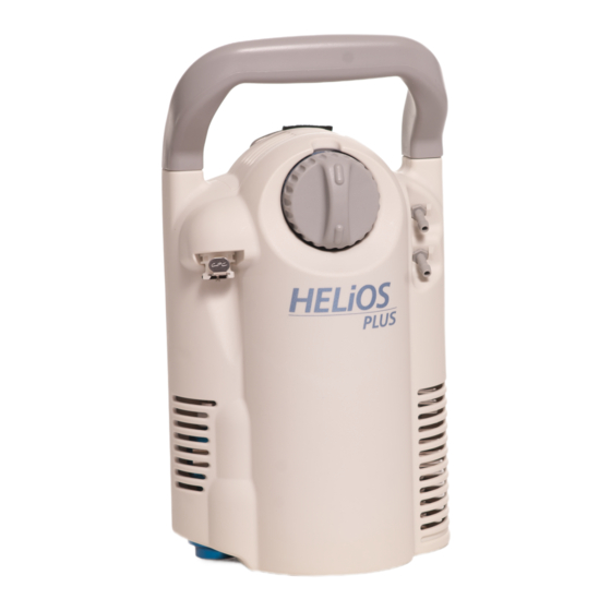
Equipment Description Figure 3: HELiOS portables components The HELiOS 300 and HELiOS 850 are lightweight portable liquid oxygen units designed to deliver supplementary oxygen therapy to patients as prescribed by a physician. The units are filled from a liquid reservoir for ambulatory use, or used as a stationary conserving device when attached to a HELiOS reser- voir using a flexible oxygen supply line. -
Page 9: Theory Of Operation
The H300 & H850 potable units are designed to be filled from any top-fill (TF) reservoir with a standard Puritan Bennett male fill connector (QDV). Below is a list of CAIRE reservoirs that will fill the H300 & H850. •... - Page 10 Theory of Operation If the pressure in the container increases over the economizer Standby valve setting, the economizer valve opens again and the cycle When the H300 or H850 contains liquid oxygen, the vent valve repeats. This maintains the correct gaseous oxygen flow to the is closed, and there is no flow demand, the pressure in the system patient at all times.
- Page 11 Theory of Operation An initial volume of oxygen (called a bolus) is delivered imme- Oxygen Delivery diately when a patient breathes in. The amount of oxygen that is delivered in this bolus is determined by the setting selected on The H300 & H850 are equipped with a pneumatic demand flow the FCV.
- Page 12 Theory of Operation Continuous Flow Serial Number Identification When the FCV is on continuous (C) mode, the oxygen flow 1 Units manufactured prior to October 2010 are identified by is delivered in a continuous stream rather than a bolus and tail unique 8-digit serial numbers shown in Figure 12.
-
Page 13: Specifications
Specifications Table 4: Equipment Specifications HELiOS Plus (H300) HELiOS Marathon (H850) Volume of LOX (typical) 0.38 L 0.84 L Weight of LOX at 24 psig (166 kPa) 0.9 lb (0.41 kg) 2.0 lb (0.90 kg) Saturation (typical) Gaseous Oxygen Equivalent @ 1atm. -
Page 14: Saturation Principles
Saturation Principles Oxygen, in its normal state, is a colorless, tasteless, and odorless gas that is non-flammable, although it greatly accelerates combustion in high concentrations. It constitutes about 21% of the Earth’s atmosphere by volume. Oxygen in higher concentrations is medically beneficial to patients suffering from certain respiratory diseases. - Page 15 Saturation Principles If the pressure in a container of saturated liquid decreases, the temperature required for saturation to occur will decrease. This leaves the liquid “super saturated” or too warm. When this occurs, rapid boiling and vaporizing of some of the liquid occurs. The rapid boil- ing and evaporation of the liquid dissipates the excessive heat until the remaining liquid cools down to the new saturation temperature associated with the decreased pressure (Figure 16).
- Page 16 Saturation Principles If the saturation pressure of the liquid in the portable is greater than 1.93 bar (28 psi) the following symptoms may occur: • Increased product loss and evaporation rate • Decreased durations • High flow rates • Continuous flow on demand settings •...
-
Page 17: Unpacking And Setup
VIII Unpacking and Setup Unpacking 1. Inspect carton for shipping damage. Report any damage to freight company before signing bill of lading. 2. Check description on carton against your order. 3. Unpack unit, including all accessories and documenta- tion. 4. Set aside packing materials in case unit must be returned to the factory. -
Page 18: Operation
Operation 11. Hold the handle on the H300 or H850 and push the release Filling button on the reservoir down until the fill connectors separate. 1. Dry the male QDV on the reservoir using a clean, dry, lint- free cloth. NOTE: If the H300 or H850 does not separate easily, do not use force. - Page 19 Operation Operation (Using the Oxygen Supply Line) WARNING: Use only the recommended flexible oxygen supply tube and oxygen gas source. Connecting the unit to 1. Verify that there is adequate liquid oxygen in the reservoir. an incorrect gas source can cause inhalation of hazardous substances.
- Page 20 4. Dry all components thoroughly with a dry towel and oil-free compressed gas. NOTE: Only use disinfectants or cleaning agents approved for use with this equipment by CAIRE such as Sporicidin, Hydroklean, or others as specified by CAIRE. HELiOS Portables Technical Service Manual • PN 20562190 Rev E...
-
Page 21: Maintenance
Inspect the outer container for cold sweaty conditions distributor maximum flexibility while assuring that the equip- and excessive venting from the relief valve. ment is operating properly. CAIRE suggests a continuous (as c. NER Test (RP22) needed) and biennial (24-month) schedule for routine mainte- d. -
Page 22: Introduction
Maintenance Schedule A (Biennial) Maintenance Checklist Unit Serial Number: Step 10 Year Service Life Year 2 Year 4 Year 6 Year 8 Year 10 LOX Purged From Reservoir (Repair Procedure RP3) Performed or Verified By/Date Inpection for Damaged/Missing Parts Performed or Verified By/Date Contents Indicator Reads Empty and Spring Scale Moves Performed or Verified By/Date Freely... -
Page 23: Troubleshooting Charts
Maintenance Schedule B – Continuous (As Needed) Schedule A. Introduction Continuous maintenance is a set of tests and inspections to be done periodically to ensure that the equipment is functioning properly. It can be done while the equipment is in service by drivers or other personnel. - Page 24 Maintenance Schedule B (Continuous Pre and Post Fill Inspection) Maintenance Checklist Unit Serial Number: Pre Fill Visual Inspection Cracking, Discoloration or Warping Verified By/Date QDV Deformation Verified By/Date Liquid Contents/Level Indicator Functionality Verified By/Date Cryogenic Reservoir Damage (Dents,Dings) Verified By/Date Visible Dirt or Contamination Verified By/Date Presence of All Required Labels...
-
Page 25: Troubleshooting & Repair Procedures
Troubleshooting & Repair Procedures Table of Contents Introduction ----------------------------------------------------------------------------------------- 20 Troubleshooting Charts ------------------------------------------------------------------------21–27 Repair Procedures General --------------------------------------------------------------------------------- 31 Liquid Leak Detector Test ----------------------------------------------------------- 31 RP3A Emptying the Unit (H300) ----------------------------------------------------------- 33 RP3B Emptying the Unit (H850) ----------------------------------------------------------- 33 Cover Removal ------------------------------------------------------------------------ 34 RP5A Front Cover R/R ---------------------------------------------------------------------- 34 RP5B... - Page 26 Troubleshooting & Repair Procedures Table 6 below provides troubleshooting procedures for the HELiOS portables. This guide is not all-inclusive but is intended to serve as a general outline for solving operational problems. The table describes symptoms, identifies probable causes, and suggests correc- tive actions.
- Page 27 Test the relief valve (RP7 & RP8) and replace if necessary d) Faulty relief valve (RP10 & RP11) Partial or complete loss of Conduct the NER test (RP22) and return the unit to CAIRE, vacuum inc. if necessary. No Flow...
- Page 28 Troubleshooting & Repair Procedures Table 6 (cont.) Symptom Probable Cause Corrective Action Ensure that there is no venting from the vent valve outlet/tube. If Vent valve is open there is refer to the corrective actions for “Liquid leaks from the vent valve tube/outlet”...
- Page 29 “Excessive venting from relief valves (hissing sound)” Partial or complete loss of vac- Conduct the NER test (RP22) and return the unit to CAIRE, Inc. if necessary. 13) Excessive Frost Some frost on the outer case and on the plumbing is acceptable, NOTE: Minimal especially at high flow rates during continuous use.
- Page 30 Troubleshooting & Repair Procedures Table 6 (cont.) Symptom Probable Cause Corrective Action 14) Unit will not main- Inspect the saturation pressure of the reservoir used for filling. Saturation pressure is out of tain acceptable pres- Allow at least 30 minutes at no flow for the portable to saturate specification sure when in use properly.
- Page 31 Troubleshooting & Repair Procedures HELiOS Portables Technical Service Manual • PN 20562190 Rev E...
- Page 32 Troubleshooting & Repair Procedures HELiOS Portables Technical Service Manual • PN 20562190 Rev E...
-
Page 33: Rp1 General
Troubleshooting & Repair Procedures RP1 – General RP2 – Liquid Leak Detector Test The following procedures have been carefully prepared to allow 1. Remove the covers (RP4). proper removal and replacement of defective components and should be used in conjunction with the Troubleshooting Chart and 2. - Page 34 Troubleshooting & Repair Procedures bling occurs, replace the inline check valve (RP24). 14. Disconnect the test pressure gauge and the HELiOS oxygen supply line. 15. Reinstall the case (RP4). NOTE: This is not required for newer units manufactured without the CPC Fitting. Figure 20: Pressurizing the HELiOS Portable 9.
-
Page 35: Rp3A Emptying The Unit (H300)
Troubleshooting & Repair Procedures 6. Squeeze the tube connected to the bottom cannula barb. RP3A – Emptying the Unit (H300) You should hear and/or feel a continuous flow of oxygen 1. Set the flow control valve to a setting of 4. coming from the open connection of the Jet Venturi. -
Page 36: Rp4 Cover Removal
Troubleshooting & Repair Procedures RP4 – Cover Removal 1. Empty the unit (RP3). 2. Place the unit on its side with the rear cover facing you. 3. Use a T10 Torx driver to remove the Torx screws (7 in the H300, 10 in the H850) from the rear cover. -
Page 37: Rp5B Rear Cover R/R
Troubleshooting & Repair Procedures 8. Remove the nut that secures the oxygen supply line quick NOTE: Install the steel pull handle so that the arm with two connect to the front cover using a 5/8 inch open-end wrench. holes is the farthest from the vent lever opening. Insert the straight leg of the hitch pin through the upper hole in the pull NOTE: This is not required for units manufactured without handle until the pin snaps into place. -
Page 38: Rp7 Primary Relief Valve Test
Troubleshooting & Repair Procedures RP7 – Primary Relief Valve Test 1. Remove the covers (RP4). 2. Set the container assembly on the portable test fixture (B- 778202-00). NOTE: For newer units manufactured without the CPC Connector, the CPC Connector Kit will need to be installed, please refer to RP27. -
Page 39: Rp8 Secondary Relief Valve Test
Troubleshooting & Repair Procedures (1.27 cm) long. Place the smaller end of the rubber stopper RP8 – Secondary Relief Valve Test over the R/E valve vent port. Position the bar clamp station- 1. Remove the covers (RP4). ary arm on the larger end of the stopper and the moveable arm on the R/E valve body. -
Page 40: Rp9A Economizer Test (H300)
Troubleshooting & Repair Procedures 15. If the economizer pressure is not within 1.41-1.59 bar (20.5- RP9A – Economizer Test (H300) 23.0 psi), replace the R/E valve (RP10). 1. Make sure the unit has been leak tested (RP2). 16. Reassemble the unit by reversing steps 1-12. 2. -
Page 41: Rp10 R/E Valve R/R
Troubleshooting & Repair Procedures 13. Install the barbed fitting in the R/E valve outlet arm. RP10 – R/E Valve R/R 1. Remove the covers (RP4). 14. Install the flexible urethane tube on the barbed fitting. 2. Remove the flexible urethane tube from the barbed fitting on NOTE: The R/E valve arms should face the container. -
Page 42: Rp12 Pressure Hold Test
Troubleshooting & Repair Procedures RP13A – Liquid Withdrawal Warming Coil R/R (H300) RP12 – Pressure Hold Test 1. Remove the covers (RP4). 1. Attach a test pressure gauge (B-701732-00) to the top can- nula barb on the front cover of the H300 or H850. 2. -
Page 43: Rp13B Liquid Withdrawl Warming Coil R/R (H850)
Troubleshooting & Repair Procedures RP13B – Liquid Withdrawal Warming Coil R/R (H850) 1. Remove the covers (RP4). 2. Remove the flexible urethane tube from the barbed fitting on the R/E outlet arm. 3. Remove the flexible urethane tube from the barbed fitting on the side of the vent valve. -
Page 44: Rp14A Gas Withdrawl Warming Coil R/R (H300)
Troubleshooting & Repair Procedures 5. Use a 7/16 inch open-end wrench to hold the manifold block RP14A – Gas Withdrawal Warming Coil R/R (H300) on the top of the container stationary. Use a 7/16 inch open- 1. Remove the covers (RP4). end wrench to remove the remaining gas withdrawal coil compression nut from the manifold block. -
Page 45: Rp15B Vent Valve Assembly R/R (H850)
Troubleshooting & Repair Procedures 4. Remove the torsion spring. RP15B – Vent Valve Assembly R/R (H850) 1. Remove the covers (RP4). 5. Remove the vent tube barbed fitting using a 1/4 inch open- end wrench. 2. Disconnect the flexible vent tube from the barbed fitting on the side of the vent valve. -
Page 46: Rp17A Qdv Assembly R/R (H300)
Troubleshooting & Repair Procedures RP17A – QDV Assembly R/R (H300) 1. Remove the case (RP4). 2. Use an adjustable wrench to hold the fill connector mount- ing bracket stationary. Use a second 9/16 inch open-end wrench to remove the fill on the machined flats of the fill connector body to loosen and remove the compression nut of the fill tube from the top of the fill connector. -
Page 47: Rp17B Qdv Assembly R/R (H850)
Troubleshooting & Repair Procedures RP17B – QDV Assembly R/R (H850) RP18 – QDV Lip Seal R/R 1. Remove the covers (RP4). 1. Remove the QDV (RP17). 2. Use an adjustable wrench to hold the fill connector adaptor 2. Hold the QDV body with an adjustable wrench placed on stationary. -
Page 48: Rp19 Demand Flow Control Valve Test
Troubleshooting & Repair Procedures 14. Set the flow control knob to the lowest continuous flow set- RP19 – Demand Flow Control Valve Test ting (0.12 for the H300, C1 for the H850) 1. Make sure the unit has been leak tested (RP2). 15. - Page 49 Troubleshooting & Repair Procedures Table 8: H850 Flow Tolerance Flow Specification Acceptable Measured Flow Setting (LPM) Range (LPM) D1.5 Tail Flow 0.65 0.5 - 0.8 Tail Flow 0.75 0.6 - 0.9 D2.5 Tail Flow 1.00 0.85 - 1.15 Tail Flow 1.50 1.3 - 1.7 Tail Flow...
-
Page 50: Rp20 Demand Fcv R/R
Troubleshooting & Repair Procedures 5. Push the replacement filter screen into the inlet port until it RP20 – Demand FCV R/R is seated on the internal support ledge. 1. Remove the covers (RP4). NOTE: Do not install two filter screens. This may cause a flow 2. - Page 51 registers on the test flowmeter. Verify a pressure reading of .038-.043-in. (.097-.109-cm) H2O vacuum on the Magnehelic gauge. 7. If the Magnehelic gauge reads less than .038-in. (.097-cm) H2O when oxygen flow first registers in step 6, adjust the demand flow control valve as follows. With the H300 or H850 laying flat on the work table, position the top one third of the unit over the edge of the table.
-
Page 52: Rp22 Normal Evaporation Rate (Ner) Test
Troubleshooting & Repair Procedures RP23 – Oxygen Supply Line Quick Connect R/R RP22 – Normal Evaporation Rate (NER) Test 1. Remove the case (RP4). 1) Ensure the unit has been leak tested (RP2). 2. Use a small flat head screwdriver to carefully pry the 2) Fill the H300 or H850 from a properly saturated source of urethane tube from the inlet barbed fitting of the inline liquid oxygen. -
Page 53: Parts List
Troubleshooting & Repair Procedures RP25 – Compression Fitting (Nut & Ferrule) RP26 – Flexible Tubing Replacement Replacement 1. Use a small flat-blade screwdriver to carefully back the 1. Inspect the tube end. Make sure that it is cut square and that brass collar (when used) off of the barbed fitting. -
Page 54: Ordering Information
Parts Price List Contact Customer Service or visit www.cairemedical.com to obtain your parts list. HELiOS Portables Technical Service Manual • PN 20562190 Rev E... -
Page 55: Return & Restocking Policy
Quantity, part number, description, and unit cost specify when placing order. for each item ordered. 3. Telephone or fax CAIRE Inc. at one of the numbers listed below to begin immediate processing of the order: For additional ordering and contact... -
Page 56: Service Tools/Equipment/Supplies
Section VIII, Unpacking and Setup Instructions. If it becomes necessary to cancel an order with CAIRE Inc. after the shipment has been received, use the following “Restock If a problem with the unit should be encountered, reference Policy”... - Page 57 Service Tools/Equipment/Supplies Table #9 Table #11 Required Tools Required Supplies Adjustable Wrench – 10 inch Household Glass Cleaner Adjustable Wrench – 8 inch Krytox Lubricant Clamp or Hemostat Lint-Free Cloth Dental Pick Flat Head Screwdriver Snoop Liquid Leak Detector Hex (Allen) Wrenches - Various Sizes TEFLON Tape Jewler’s Screwdriver Scotch Brite Adhesive Pad...
- Page 58 Service Tools/Equipment/Supplies Tools and Accessories available from CAIRE Description Item Number Backpack H850 069209 Belt Pack H300 B-701654-00 Belt Pack H300 Large Waist Extension 14951835 CPC Quick Connect Kit 20748595 DISS Adaptor B-776945-00 Dual Lumen Cannula – 5 ft (1.5 m) Delivery Both Nostrils (Concentric) 10035468 Dual Lumen Cannula –...
- Page 59 . c a i r e m e d i c a l . c o m Copyright © 2019 CAIRE Inc. reserves the right to discontinue its products, or change the prices, materials, equipment, quality, descriptions, specifications and/or processes to its products at any time without prior notice and with no further obligation or consequence.
Need help?
Do you have a question about the HELiOS Plus and is the answer not in the manual?
Questions and answers