
Related Manuals for Toro CM-1258Y-SD

Summary of Contents for Toro CM-1258Y-SD
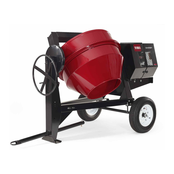
- Page 1 Form No. 3398-640 Rev A CM-1258Y-SD Concrete Mixer Model No. 68011—Serial No. 316000001 and Up g019992 *3398-640* A Register at www.Toro.com. Original Instructions (EN)
- Page 2 The DOT tire information is located on the side You may contact Toro directly at www.Toro.com for product of each tire. This information gives load and speed and accessory information, help finding a dealer, or to register ratings.
-
Page 3: Table Of Contents
Contents Safety Improperly using or maintaining the machine can result Safety ................3 in injury. To reduce the potential for injury, comply with Safe Operating Practices........... 3 these safety instructions and always pay attention to the Safety and Instructional Decals ......... 6 safety alert symbol , which means: Caution , Warning , Setup ................ - Page 4 Preparation • Never let children or untrained people operate or service the equipment. Local regulations may restrict the age of Become familiar with the safe operation of the equipment, the operator. operator controls, and safety signs. • The owner/user can prevent and is responsible for •...
- Page 5 Keep equipment in good condition. • Do not touch parts which may be hot from operation. • Use only genuine Toro replacement parts to ensure that Allow them to cool before attempting to maintain, adjust, the original standards are maintained. or service the machine.
-
Page 6: Safety And Instructional Decals
Safety and Instructional Decals Safety decals and instructions are easily visible to the operator and are located near any area of potential danger. Replace any decal that is damaged or lost. 132–7176 1. Pull up to start the engine. 2. Push down to stop the engine. - Page 7 125–4939 1. Warning—read the 4. Toxic gas inhalation Operator’s Manual. hazard—Do not run the engine in an enclosed space. 2. Hand and arm 5. Explosion hazard—stop entanglement at the chain the engine and keep drive; crushing hazard away from flames when of hand;...
-
Page 8: Setup
Setup Loose Parts Use the chart below to verify that all parts have been shipped. Procedure Description Qty. Tow pole kit (sold separately) Install the tow pole. Safety chain Install the safety chain. Connecting link 3. Insert the bolt through the holes in the fitting and the pole (Figure 4. -
Page 9: Installing The Safety Chain
Product Overview Installing the Safety Chain Parts needed for this procedure: Safety chain Connecting link Installing the Safety Chain 1. Form a hook on the end of a bendable piece of rod or stiff wire (not included), and insert it through both keyholes in the front post of the machine (Figure 4A). - Page 10 Engine Controls Engine Speed Control Handle The engine-speed-control handle (Figure 7) allows the operator to start and stop the engine. It is located on the engine cowl, and is connected to the engine-speed-control knob, which is located on the engine (Figure 8).
- Page 11 Recoil-Start Handle To start the engine, pull the recoil-start handle (Figure quickly to turn the engine over. The engine controls described above must all be set correctly for the engine to start. g020001 Figure 8 1. Engine-speed-control knob Fuel-Shutoff Lever The fuel-shutoff lever is located underneath the fuel tank.
-
Page 12: Specifications
Specifications Operation Note: Specifications and design are subject to change Important: Before operating the machine, check the without notice. fuel and oil levels and remove debris from the machine. Batch Capacity 0.34 m Ensure that the area is clear of people. (12 ft Total Volume 0.56 m... - Page 13 G020836 Figure 12 1. Example of tire wear caused by underinflation G019733 Figure 11 Drum-Tilt Brake 1. Unlocked position 2. Locked position Figure 13 1. Example of tire wear caused by overinflation 4. Ensure that the engine cowl is closed and latched; refer Closing the Cowl (page 17).
- Page 14 G021 Figure 14 Hitching a Machine with a Stamped Ball Coupler 1. Apply chassis grease to the socket of the coupler and the area of the clamp that contacts the ball. 2. Oil the pivot points and sliding surfaces of the coupler with SAE 30 motor oil.
- Page 15 Hitching a Machine with a Forged Ball Hitching a Machine with a Pintle Hitch Coupler Tow Pole 1. Apply removable thread-locking compound to the 1. Remove the pin from the pintle hitch and open it threads of the coupler bolt to prevent the coupler (Figure 17).
-
Page 16: Towing The Machine
Connecting the Safety Chains to the Tow Vehicle Connect the safety chain to the machine and the tow vehicle as follows: 1. Pull the safety chain through the slots in the keyholes located in the front post of the machine, so that there is just enough slack on each side for turning around corners when towing the machine Figure... -
Page 17: Preparing To Use The Machine
Preparing to Use the Machine • Review all of the safety decals on the machine. • Use a hard-hat, hearing protection, a shirt with long sleeves that are tight at the wrists, tight-fitting gloves without draw strings or loose cuffs, eye protection, and a dust mask or respirator. -
Page 18: Adding Fuel
Adding Fuel DANGER • Use only ultra-low sulfur (< 15 ppm) diesel fuel. In certain conditions during fueling, static electricity can be released causing a spark which • Purchase fuel in quantities that can be used within 30 days can ignite the fuel vapors. A fire or explosion from to ensure fuel freshness. -
Page 19: Checking The Engine-Oil Level
5. Wipe up any fuel that may have spilled. Checking the Engine-Oil Level Service Interval: Before each use or daily—Check the engine-oil level. Toro Premium Engine Oil is available from your Authorized Toro Dealer. Important: Use 4-cycle engine oil that meets or exceeds the following guidelines and classifications: •... -
Page 20: Starting And Stopping The Engine
5. Slide the dipstick fully into the fill port without SAE 10W threading it into the port (Figure 24). SAE 20W 6. Remove the dipstick and look at the end. If the engine oil level is below the halfway point on the hatchmarks, SAE 10W -30 slowly pour only enough oil into the fill port to raise SAE 15W -40... - Page 21 6. Grasp the recoil-start handle, pull it out slowly until you feel resistance, then pull it all the way out with a strong and even motion (Figure 28). Note: Use 2 hands if necessary. g020001 Figure 26 g020367 Figure 28 1.
-
Page 22: Using The Machine
Using the Machine Concrete has the following 4 basic ingredients: • Sand DANGER • Gravel This machine is capable of amputating hands. • Portland cement • Stay in the operator’s position while the machine • Water is running. Depending on the application, you can use different ratios •... - Page 23 Dumping the Drum Note: When dumping a batch of material, leave the engine running so that the rotating drum helps dump the material. 1. Align a wheelbarrow or similar container of adequate capacity in the path of the drum opening. 2.
-
Page 24: Maintenance
Maintenance Important: Before performing any maintenance procedures, stop the engine and wait 5 minutes to allow all moving parts to come to a complete stop and cool. Recommended Maintenance Schedule(s) Maintenance Service Maintenance Procedure Interval • Change the engine oil. After the first 25 hours •... -
Page 25: Lubrication
Lubrication 3. To remove the divider plate, lift it upward and rotate it counterclockwise so that it clears various engine components. Lubricating the Machine Installing the Divider Plate Service Interval: Monthly—Grease the trunnions and the 1. Guide the divider plate into position against the front drum spindle. -
Page 26: Lubricating The Drive Chain
Lubricating the Drive Chain Engine Maintenance Service Interval: Every 40 hours—Lubricate the drive chain Servicing the Air Cleaner with a non-sticky chain lubricant. Apply a chain lubricant that is non-sticky to help prevent dirt Service Interval: Before each use or daily—Inspect the air and abrasive particles from sticking to the chain (Figure 32). -
Page 27: Changing The Engine Oil
Service Interval: After the first 25 hours—Change the engine oil. Every 100 hours—Change the engine oil. Toro Premium Engine Oil is available from your Authorized Toro Dealer. Important: Use 4-cycle engine oil that meets or exceeds the following guidelines and classifications: •... -
Page 28: Servicing The Engine-Oil Filter
Filling the Engine Crankcase with Oil 1. Remove the dipstick (Figure 36) and slowly pour oil into the fill hole until the oil is between the upper and lower limit on the dipstick. g020389 Figure 37 1. Oil filter 3. Oil-filter retaining bolt 2. -
Page 29: Removing And Installing The Engine
Removing and Installing the Fuel System Engine Maintenance Removing the Engine Servicing the Fuel System 1. Open the rear cowl; refer to Opening the Cowl (page 17). Cleaning the Inlet-Fuel Screen 2. Remove the 4 nuts and bolts that secure the engine to the engine-mounting plate (Figure 38). - Page 30 Draining the Fuel Tank and Replacing 7. Pull the outlet-fuel filter and gasket out of the filler port (Figure 41). the Outlet Fuel Filter 8. Install a new outlet-fuel filter and gasket through the Service Interval: Every 200 hours—Replace the outlet-fuel filler port, and seat them in the fuel tank (Figure 41).
-
Page 31: Drive System Maintenance
Servicing the Drive Chain Drive System Maintenance Service Interval: Every 20 hours—Inspect the drive chain for rust and debris. Every 20 hours—Inspect the drive chain tension and Servicing the Reduction Case adjust it as necessary. Changing the Reduction Case Oil Checking the Drive Chain 1. -
Page 32: Cleaning
Cleaning 3. Slide the engine left to increase tension on the drive chain or right to decrease tension. 4. When the chain has the appropriate amount of tension; Cleaning the Machine refer to Checking the Drive Chain Tension (page 31), torque the 4 nuts and bolts to 24 N•m (18 ft-lb) each. -
Page 33: Storage
Storage Storing the Machine Whenever you store the machine over 30 days, prepare it as follows: 1. Clean the machine; refer to Cleaning the Machine (page 32). 2. Start the engine. Allow the engine to idle for 3 minutes and then stop the engine. 3. -
Page 34: Troubleshooting
Troubleshooting Problem Possible Cause Corrective Action The engine dose not start. 1. On the engine cowl, the 1. Pull the engine-speed-control handle engine-speed-control handle is to the position and lock it. START not all the way into the position. START 2. - Page 35 Notes:...
- Page 36 Toro importer. If all other remedies fail, you may contact us at Toro Warranty Company. Australian Consumer Law: Australian customers will find details relating to the Australian Consumer Law either inside the box or at your local Toro Dealer.