Table of Contents
Advertisement
Advertisement
Table of Contents

Related Manuals for Instron AVE2


Summary of Contents for Instron AVE2
- Page 1 Instron Video Extensometer AVE2 and SVE2 Operator’s Guide M16-16905-EN Revision D...
- Page 2 Instron is a registered trademark of Illinois Tool Works Inc. (ITW). Other names, logos, icons and marks identifying Instron products and services referenced herein are trademarks of ITW and may not be used without the prior written permission of ITW.
- Page 3 Caution is used where a hazard may lead to damage to equipment or to loss of data. Instron products, to the best of its knowledge, comply with various national and international safety standards, in as much as they apply to materials and structural testing.
- Page 4 Preliminary Pages Warnings Hazard - Press the Emergency Stop button whenever you consider that an unsafe condition exists. The Emergency Stop button removes hydraulic power or electrical drive from the testing system and brings the hazardous elements of the system to a stop as quickly as possible.
- Page 5 During system operation, keep away from the operating envelope of the robot. De-activate the robot before entering the envelope for any purpose, such as reloading the specimen magazine. Product Support: www.instron.com...
- Page 6 Preliminary Pages Warnings Hazard - Set the appropriate limits before performing loop tuning or running waveforms or tests. Operational limits are included within your testing system to suspend motion or shut off the system when upper and/or lower bounds of actuator or crosshead travel, or force or strain, are reached during testing.
- Page 7 Apply the specified torque to all load string fasteners and the correct setting to wedge washers or spiral washers. Visually inspect highly stressed components such as grips and threaded adapters prior to every fatigue test for signs of wear or fatigue damage. Product Support: www.instron.com...
- Page 8 Preliminary Pages M16-16905-EN...
-
Page 9: Table Of Contents
AverEdge32™ option (AVE2 only) ........ - Page 10 Non-integrated testing systems ..........Calibrate in the Instron Video Extensometer application..... . .
- Page 11 Index ..............85 Product Support: www.instron.com...
- Page 12 Preliminary Pages M16-16905-EN...
-
Page 13: Chapter 1: Introduction
The principle of the video extensometer is based upon accurate detection of the gauge length markers using a high resolution digital video camera. There are two models of the second generation Instron video extensometer; the AVE2 (Advanced Video Extensometer) and the SVE2 (Standard Video Extensometer). -
Page 14: Averedge32™ Option (Ave2 Only)
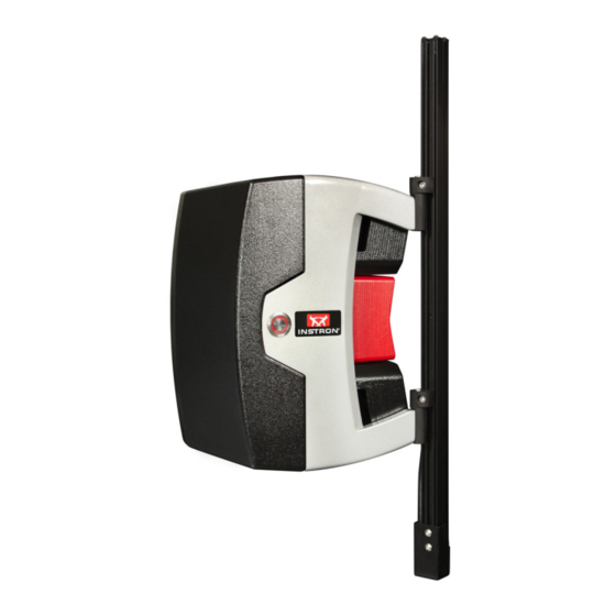
Chapter: Introduction Figure 1. AVE2 AverEdge32™ option (AVE2 only) The AverEdge32™ option, available for the AVE2, is an advanced capability available in ® Bluehill Universal software for measuring strain using the edges of the specimen instead of dots placed on the specimen. It requires a different mounting system that includes a back screen. -
Page 15: Product Support
If you cannot find answers in these sources, contact Instron’s Service department directly. A list of Instron offices is available on our website at www.instron.com. In the US and Canada, you can call directly at 1-800-473-7838. Product documentation Instron offers a comprehensive range of documentation to help you get the most out of your Instron products. - Page 16 Chapter: Introduction M16-16905-EN...
-
Page 17: Chapter 2: Specifications
Software compatibility..........22 General Standard Mounting Configuration The following tables contain specifications for the AVE2 and SVE2 when installed on different testing machines using the standard mounting configuration. Refer to “AverEdge32™ Mounting Configuration”... - Page 18 Chapter: Specifications Table 1. Table model testers, (e.g. 5940 and 5960) ElectroPuls and 8800 testing systems (Continued) Lens focal length (mm) AVE2 measurement accuracy the greater of: (axial and transverse) (μm) (the ±1 or ±0.5% ±1 or ±0.5% ±3 or ±1% of ±9 or ±1% of...
-
Page 19: Averedge32™ Mounting Configuration
Transverse field of view (mm) not suitable Minimum axial gauge length (mm) not suitable Minimum transverse gauge width not suitable (mm) AVE2 resolution (µm) not suitable SVE2 resolution (µm) not suitable AVE2 measurement accuracy the greater of: (axial and transverse) (µm) (the ±1 or ±0.5%... - Page 20 Transverse field of view (mm) Minimum axial gauge length (mm) Minimum transverse gauge width (mm) 12.5 AVE2 resolution (μm) AVE2 axial measurement accuracy (μm) ±1 or ±0.5% of reading, whichever is greater AVE2 transverse measurement accuracy (μm) ±3 or ±1% of reading, whichever is...
-
Page 21: Environmental
Conformity with EU directives ® Instron declares under our sole responsibility that AVE2 and SVE2 video extensometers and associated accessories are in conformity with all relevant provisions of the following regulations: •... -
Page 22: Dimensions And Weight
Any compatible system using the AverEdge32™ for Bluehill V4.19 or later transverse measurement (AVE2 only) If you are using an 8800 or ElectroPuls system for static testing, the AVE2 is compatible with the following versions of software: • Console V8.9 or later •... - Page 23 Software compatibility • Console V8.11 or later • Firmware V12.15 or later • WaveMatrix V1.9 or later • ® Bluehill V3.67 or later Product Support: www.instron.com...
- Page 24 Chapter: Specifications M16-16905-EN...
-
Page 25: Installation
System interconnections..........47 Initial installation Initial installation is performed by an Instron service engineer and includes the following: •... -
Page 26: Moving Between Machines
For the purposes of installation and moving between testing machines, the AVE2 and SVE2 are identical. All references to AVE2 in the following sections also apply to SVE2. Figure 2 on page shows the T-nut (A) inserted in the appropriate slot in the column on the frame. -
Page 27: Electromechanical Dual Column Table Top Testing Machines
The optional AverEdge32™ configuration uses the same mounting methods but a different mounting bracket and an additional back screen. Refer to “AverEdge32™ configuration” on page 31. Figure 3. AVE2 on a 5960 dual column table top testing machine Product Support: www.instron.com... - Page 28 Alternative mounting location If the T-slot on the left front of the testing machine is already occupied by another accessory (a debris shield, for example), you can mount the AVE2 in the T-slot on the right rear (see Figure 5 on page 29).
- Page 29 Moving between machines Figure 5. AVE2 alternative location The motor cover on the testing machine restricts the lower limit of travel of the AVE2. Product Support: www.instron.com...
- Page 30 Chapter: Installation Caution Make sure that the bottom bracket is at least 25mm above the top of the motor cover to allow adequate cooling (see Figure 6 on page 30). Figure 6. AVE2 alternative location - minimum clearance M16-16905-EN...
- Page 31 The mounting bracket and additional back screen are shown in Figure 7 on page mounted on a 6800 series testing system. Figure 7. Installation shown on a 6800 Series testing system Product Support: www.instron.com...
-
Page 32: Electromechanical Single Column Testing Machines
Chapter: Installation Figure 8 on page shows the footprint dimensions of the AverEdge32™ configuration on a 6800 Series testing system, including the back screen (1). Note that the mounting bracket and back screen are installed in the T-slot closest to the outer edge of each column. - Page 33 Figure 10 on page show the AVE2 installed on a 5940 single column testing machine. Dimensions are in mm. The mounting bracket (A) is designed for use with a single column testing machine only. Make sure that you mount the bracket into the second T-slot from the front of the...
- Page 34 Chapter: Installation Figure 9. AVE2 on a 5940 single column testing machine M16-16905-EN...
- Page 35 Moving between machines Figure 10. Footprint of AVE2 on a 5940 single column testing machine Product Support: www.instron.com...
-
Page 36: 5980 (Not 5988 Or 5989) Floor Model Testing Machines
Chapter: Installation Figure 11. AVE2 mounted in second slot from front of 5940 5980 (not 5988 or 5989) Floor model testing machines Figure 12 on page Figure 13 on page show the AVE2 installed on a 5985 floor model testing machine. Dimensions are in mm. - Page 37 Moving between machines Figure 12. AVE2 on a 5985 dual column floor model testing machine Product Support: www.instron.com...
- Page 38 Chapter: Installation Figure 13. Footprint of AVE2 on a 5985 dual column floor model testing machine AverEdge32™ configuration The optional AverEdge32™ configuration uses the same mounting methods as the standard configuration but a different mounting bracket and light bar position. The...
- Page 39 AverEdge32™ configuration on a 5980 Series testing system, including the back screen (1). Note that the mounting bracket and back screen are installed in the second T-slot from the outer edge of each column. Product Support: www.instron.com...
-
Page 40: 5988 And 5989 High-Capacity Floor Model Testing Machines
Figure 17 on page show the AVE2 installed on a 5988 high capacity floor model testing machine. Dimensions are in mm. The mounting bracket (A) is the same angled bracket that is used on the 5960 dual column table model but with additional spacers (B). - Page 41 Moving between machines Figure 16. AVE2 on a 5988 or 5989 floor model testing machine Product Support: www.instron.com...
-
Page 42: Lx Static Hydraulic Testing Machines
Chapter: Installation Figure 17. Footprint of AVE2 on a 5988 or 5989 floor model testing machine LX Static hydraulic testing machines Figure 18 on page Figure 19 on page show the AVE2 installed on an LX static hydraulic testing machine. Dimensions are in mm. - Page 43 Moving between machines Figure 18. AVE2 on a LX static hydraulic testing machine Product Support: www.instron.com...
-
Page 44: 8800 And Electropuls Testing Machines
Footprint of AVE2 on an LX static hydraulic testing machine 8800 and ElectroPuls testing machines The AVE2 is mounted to the 8800 and ElectroPuls testing machines via a plate mounted to the base platen. All 8800 and ElectroPuls machines use the same mounting plate in the same position. - Page 45 Moving between machines Figure 20. Footprint of AVE2 on an ElectroPuls testing machine Product Support: www.instron.com...
- Page 46 Chapter: Installation Figure 21. AVE2 on an 8801 series testing machine M16-16905-EN...
-
Page 47: System Interconnections
The power cable (1) and the Ethernet cable (2) are shown with the video extensometer interface cable and the video extensometer adapter cable (3). The adapter cable shown Product Support: www.instron.com... - Page 48 Chapter: Installation is appropriate for 5900 frames. Other frames have different adapter cables to accommodate different controllers. Refer to the installation drawing supplied with your load frame for more details. The sync cable (6) must be connected to the SYNC connector on the load frame if you are using DIC Replay software.
- Page 49 System interconnections Figure 23. Video extensometer connectors Product Support: www.instron.com...
- Page 50 Chapter: Installation M16-16905-EN...
-
Page 51: Chapter 4: Mark Specimens
• the camera, although they may be effective on white specimens if white marks cause problems • the shape and size of the mark must be compatible with the profile of the specimen Product Support: www.instron.com... -
Page 52: Marking Tips
Chapter: Mark specimens • applying the marks to the specimen so that they stay in place and are visible to the camera throughout the test If you are testing to a particular standard, gauge length and gauge width are often pre- defined and you must apply marks as specified in the standard. -
Page 53: Troubleshooting Ink Dots
Bleeding or wicking of the ink dots can be caused by: bleeding can occur when a specimen surface that has been prepared using an • abrasive causes the wet ink to be drawn, by capillary action, into the grooves made by the abrasive. Product Support: www.instron.com... - Page 54 Chapter: Mark specimens wicking can occur when testing woven specimens and the wet ink is drawn, by • capillary action, into the fibers of the specimen. If bleeding or wicking is a consistent problem, you should consider using tape dots. •...
-
Page 55: Chapter 5: Set Up Hardware
If the extensometer loses track of the marks on the specimen during a test, unexpected crosshead or actuator movement can occur. It is very important that you limit any such movement. The AVE2 and SVE2 can be used on a wide range of testing machines. Newer machines, ® in combination with Bluehill... -
Page 56: Averedge32™ Configuration
To examine and, if necessary, change the lens: 1. Remove the lens cover (AVE2 only; there is no lens cover on the SVE2) by gently pulling it away from the lens. You can now read the focal length of the lens printed on the body. -
Page 57: Set Up The Load String
2. Install the set of grips that will be used for testing and a typical specimen. 3. In the AVE2 tab in the Transducer dialog, enable the Show saturated pixels option. 4. View the live image of the specimen and check for any saturated pixels, which display as red dots in the image. - Page 58 Chapter: Set up hardware 5. If saturated pixels are indicated, rotate the light on the AVE2 system to the left or right to adjust the illumination. The desired result is maximum illumination of the spec- imen but without any saturated pixels.
-
Page 59: Chapter 6: Set Up Bluehill Universal
Recognition and configuration in Video extensometer recognition. No configuration required in ® Admin Bluehill software tab. Compatibility with DIC Replay Available option. Table 10. 5900 systems Connections Axial and transverse signals via Strain 1 connector to encoder. Product Support: www.instron.com... -
Page 60: Calibrate In Bluehill ® Universal Software
You should calibrate the extensometer upon initial start up and also after you change anything in the setup, such as changing a lens or changing the position of the AVE2. This procedure requires a calibration bar. If you are using a 6mm lens, then two calibration bars are required. - Page 61 6. Select Calibration. The dialog moves to the Calibration screen. 7. Remove the red lens cover (AVE2 only; there is no lens cover on the SVE2) by gently pulling it away from the lens. 8. Follow the instructions in the calibration dialog to select and focus the lens.
-
Page 62: Non-Integrated Testing Systems
Other non-integrated testing systems, including non-Instron Warning When using the 8800T or 8800D controller, the AVE2 or SVE2 is intended for strain monitoring only. It is not suitable for use as the controlling channel when conducting a test in strain control. -
Page 63: Calibrate In The Instron Video Extensometer Application
You should calibrate the extensometer upon initial start up and also after you change anything in the setup, such as changing a lens or changing the position of the AVE2. This procedure requires a calibration bar. If you are using a 6mm lens, then two calibration bars are required. - Page 64 6. Select Calibrate... to open the calibration dialog. 7. Remove the red lens cover (AVE2 only; there is no lens cover on the SVE2) by gently pulling it away from the lens. 8. Follow the instructions in the calibration dialog to select and focus the lens.
- Page 65 50mm above the bottom of the field of view to optimize accuracy. 6. Select Calibration. The dialog moves to the Calibration screen. 7. Remove the red lens cover (AVE2 only; there is no lens cover on the SVE2) by gently pulling it away from the lens. Product Support: www.instron.com...
- Page 66 8800/ElectroPuls console. As part of the manual calibration, set the transducer type to Strain (Calibration wizard > Transducer details screen). For more details refer to “Using the AVE2 with an 8800T or 8800D Controller” in the Console online help.
-
Page 67: Chapter 7: Set Up Bluehill
This is true for the older video extensometers, but is not true for AVE2 and ® SVE2; Bluehill does not create these configurations. -
Page 68: Set Up The Transverse Option
Compatibility with DIC Replay Available option. Set up the transverse option If you have purchased the AVE2 with transverse strain enabled, you will see an additional strain icon in the Bluehill console, labeled 14. To configure transverse strain: 1. Select Admin on the Home screen. -
Page 69: Calibrate In Bluehill
6. Select Calibrate... to open the calibration dialog. 7. Remove the red lens cover (AVE2 only; there is no lens cover on the SVE2) by gently pulling it away from the lens. 8. Follow the instructions in the calibration dialog to select and focus the lens. -
Page 70: Non-Integrated Testing Systems
Other non-integrated testing systems, including non-Instron Warning When using the 8800T or 8800D controller, the AVE2 or SVE2 is intended for strain monitoring only. It is not suitable for use as the controlling channel when conducting a test in strain control. -
Page 71: Calibrate In The Instron Video Extensometer Application
Not available. Calibrate in the Instron Video Extensometer application 8800 or ElectroPuls testing systems using the 8800T or 8800D controller use the Instron Video Extensometer application for calibration. You cannot calibrate the AVE2 or ® SVE2 from Bluehill The Instron Video Extensometer application is supplied with the video extensometer ®... - Page 72 6. Select Calibrate... to open the calibration dialog. 7. Remove the red lens cover (AVE2 only; there is no lens cover on the SVE2) by gently pulling it away from the lens. 8. Follow the instructions in the calibration dialog to select and focus the lens.
- Page 73 You should calibrate the extensometer upon initial start up and also after you change anything in the setup, such as changing a lens or changing the position of the AVE2. This procedure requires a calibration bar. If you are using a 6mm lens, then two calibration bars are required.
- Page 74 6. Select Calibration. The dialog moves to the Calibration screen. 7. Remove the red lens cover (AVE2 only; there is no lens cover on the SVE2) by gently pulling it away from the lens. 8. Follow the instructions in the calibration dialog to select and focus the lens.
-
Page 75: Chapter 8: Set Up Other Software (Not Bluehill ® )
® Set up systems not using Bluehill WaveMatrix™ ® If the AVE2 or SVE2 is installed on a testing machine that is not running Bluehill WaveMatrix™ software, you interact with the video extensometer through the Instron Video Extensometer Application. •... - Page 76 ® Chapter: Set up other software (not Bluehill M16-16905-EN...
-
Page 77: Run Tests
If the extensometer loses track of the marks on the specimen during a test, unexpected crosshead or actuator movement can occur. It is very important that you limit any such movement. The AVE2 and SVE2 can be used on a wide range of testing machines. Newer machines, ® in combination with Bluehill... -
Page 78: Using Bluehill ® Universal
The video extensometer is always connected to Strain 1. You can name the measurement AVE2. 2. Go to Test Control > Strain and choose the new AVE2 measurement as the primary source. 3. Go to Test Control > Pre-Test and enable auto-balance for the AVE2. -
Page 79: Using Bluehill Universal Software With Dic Replay
If you choose Speckle only, you cannot use the AVE2 as a strain device in the ®... -
Page 80: Using Bluehill ® 3
1 as the transducer configuration. The video extensometer is always connected to Strain 1. You can name the measurement AVE2. 2. Go to Test Control > Strain and choose the new AVE2 measurement as the primary source. 3. Go to Test Control > Pre-Test and enable auto-balance for the AVE2. -
Page 81: Using Wavematrix
If you choose Speckle only, you cannot use the AVE2 as a strain device in the ®... -
Page 82: Systems Not Using Bluehill ® Or Wavematrix
Chapter: Run tests ® Systems not using Bluehill or WaveMatrix™ Follow the appropriate procedures in your software for running at test using a calibrated strain transducer. Return to the Instron Video Extensometer Application whenever you need to recalibrate the instrument. M16-16905-EN... - Page 83 General............83 General The AVE2 and SVE2 require no special maintenance, apart from keeping the instrument clean and free of dust.
- Page 84 Chapter: Maintenance M16-16905-EN...
- Page 85 ..... 51 Instron Video Extensometer application 63, connections......47 contact information .
- Page 86 3400 systems ....59 5500 systems ....59 5500A systems .
- Page 88 www.instron.com...
Need help?
Do you have a question about the AVE2 and is the answer not in the manual?
Questions and answers