
Related Manuals for Clarke METALWORKER CL300M


Summary of Contents for Clarke METALWORKER CL300M
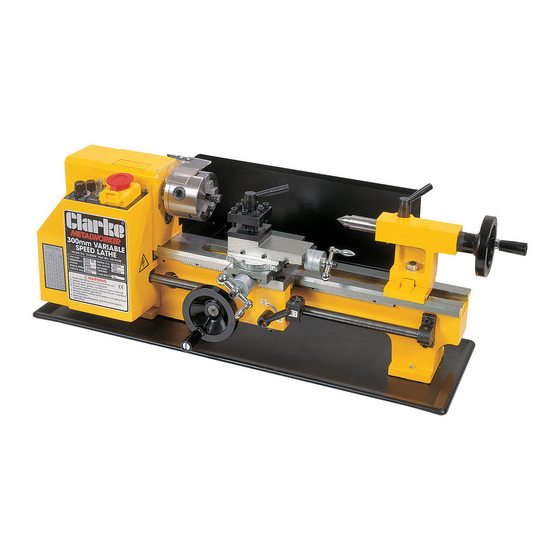
- Page 1 VARIABLE SPEED METAL LATHE MODEL NO: CL300M PART NO: 7610700 OPERATION & MAINTENANCE INSTRUCTIONS ORIGINAL INSTRUCTIONS GC1118 - ISS 6...
-
Page 2: Introduction
300mm. It is further capable of producing short tapers and Imperial threads, both left and right hand. Metric threads may also be cut with the addition of a Metric Conversion Kit, available from your Clarke dealer (see ‘Accessories’ for details). -
Page 3: Table Of Contents
TABLE OF CONTENTS Introduction Guarantee General Safety Precautions Additional Safety Rules for Lathes Electrical Connections Overview The Headstock The Running Gear The Tailstock The Saddle The Motor Unpacking and Assembly Mounting the Lathe Operation - Simple Turning Using Power Feed Bevel Cutting Screw Cutting Changing Gears for Screw Cutting... -
Page 4: General Safety Precautions
SAFETY WARNINGS WARNING: FAILURE TO FOLLOW THESE PRECAUTIONS COULD RESULT IN PERSONAL INJURY AND/OR DAMAGE TO PROPERTY. WORK ENVIRONMENT 1. Keep the work area clean and well lit. Cluttered and dark areas invite accidents. 2. Do not operate power tools in explosive atmospheres, such as in the presence of flammable liquids, gases or dust. - Page 5 2. This lathe is designed for indoor environments and must not be used for other purposes. 3. If the lathe requires repair, always contact your Clarke dealer. Always insist on original spare parts. Repairs carried out by unauthorized persons may be dangerous and invalidate the guarantee.
-
Page 6: Additional Safety Rules For Lathes
2. Do not use the power tool if the switch does not turn it on and off. Any power tool that cannot be controlled with the switch is dangerous and must be repaired. 3. Disconnect the power tool from the power supply before making any adjustments, changing accessories, or storing the tool. - Page 7 7. Ensure the tool post is secure and the cutting tool is adjusted to the correct height. 8. Ensure the workpiece is properly secured. 9. Make all adjustments with the power OFF. 10. ALWAYS cut at correct speed for the size and type of material being worked.
-
Page 8: Electrical Connections
ELECTRICAL CONNECTIONS WARNING: READ THESE ELECTRICAL SAFETY INSTRUCTIONS THOROUGHLY BEFORE CONNECTING THE PRODUCT TO THE MAINS SUPPLY. Before switching the product on, make sure that the voltage of your electricity supply is the same as that indicated on the rating plate. This product is designed to operate on 230VAC 50Hz. -
Page 9: Overview
OVERVIEW Parts & Service: 020 8988 7400 / E-mail: Parts@clarkeinternational.com or Service@clarkeinternational.com... -
Page 10: The Headstock
PARTS IDENTIFICATION Headstock Automatic Feed Lever Spindle Flange Cross-Slide Feed Handle Chuck Guard Apron 3-Jaw Chuck Manual (Saddle) Feed Handle Tool Post Leadscrew Cross-Slide Motor Brush Cap Compound Slide Thread Dial Indicator Table Tailstock Centre Running Gear Cover Tailstock Variable Speed Control Knob 10 Tailstock Securing Nut Forward/Off/Reverse Switch 11 Bed... -
Page 11: The Running Gear
(10), at its base. The Tailstock Spindle carries an internal No.2 Morse taper for use with the Centre (8) provided. A Revolving Centre and Drill Chuck are also available from your Clarke dealer. (See Accessories on page 30). -
Page 12: The Motor
THE MOTOR It is not recommended that you dis-assemble the motor. Brushes may be replaced as described under ‘Maintenance’. For all other servicing and repairs, please contact your Clarke dealer. THE OVERLOAD INDICATOR The overload indicator will light up when excessive strain is placed on the motor. -
Page 13: Unpacking And Assembly
On receipt, carefully unpack the lathe. Inspect to ensure that no damage was suffered in transit and all parts are accounted for. Should any damage be apparent or parts are missing, please contact your Clarke dealer immediately. The following loose items are to be found in the crate. -
Page 14: Mounting The Lathe
The hinged transparent chuck guard is supplied loose and must be fitted to the headstock body using the screws provided. The four rubber feet are attached to the underside of the bed using the four M6 pan head screws in the tapped holes provided. These screws are also used to secure the collecting tray. - Page 15 DURING INSTALLATION - INITIAL START 1. Taking all precautions previously stated, set the High - Low range lever (item 26 page 10)’ to LOW. 2. Ensuring the cross-slide is well away from the chuck and the automatic feed lever is in its dis-engaged position, (i.e.
- Page 16 STARTING UNDER NORMAL CONDITIONS 1. Take all necessary precautions previously stated, and ensure the workpiece can rotate fully without obstruction. 2. Set the Speed Range control lever to HIGH or LOW as required. 3. Set the Forward/O/Reverse (F/O/R) switch (C), on the main control panel, to the O (OFF) position.
-
Page 17: Operation
OPERATION SIMPLE TURNING Before starting the machine, it is imperative that the setup for the type of work to be carried out is fully checked. The following notes are guidelines as to how to set up the lathe in order to carry out a simple turning operation. - Page 18 Whilst carrying out these manoeuvres, rotate the chuck by hand to ensure that nothing will come into contact with it when turning takes place, i.e. there is adequate clearance between the saddle, cross-slide, tool post or cutting tool, and the chuck. It may be necessary to adjust the position of the compound slide or reposition the work in the chuck to guarantee that there is adequate clearance.
- Page 19 until you reach the previously marked line on the work, then retract the tool one or two complete turns on the Cross-Slide feed handle. Wind the saddle back to the beginning then wind the tool the same number of turns ‘IN’, plus the depth of desired cut, and proceed to cut once more. NOTE: This describes the procedure for general rough cutting.
-
Page 20: Bevel Cutting
the tool the same number of turns, plus the depth of cut and when ready, push down the auto feed lever and proceed to take another cut. BEVEL CUTTING Bevel cutting involves the use of the compound slide. This is mounted on the cross-slide and set at right angles to it for all normal cutting operations. - Page 21 A leadscrew, with corresponding half nuts and thread dial indicator, for the production of Metric threads is available from your Clarke dealer, see ‘Accessories’ on page 30. The general procedure for screwcutting is as follows: 1.
- Page 22 5. Observe the rotating Dial. In particular, concentrate on one of the numbered marks etched on the dial which corresponds to the scale number given in the Indicator Table. • (In our example, this could be 1,3, 5 or 7) •...
-
Page 23: Changing Gears For Screwcutting
Threads Per Inch (TPI). A leadscrew for Metric thread cutting complete with half nuts is available from your Clarke dealer. As previously mentioned, the actual thread produced will be totally dependant upon the profile of the cutting tool. It is not within the scope of this... -
Page 24: Gear Configurations
The factory setup for the lathe provides for normal turning using the power or auto feed, and the gear configuration is as follows: Gear A ....Gear B ....Gear C ....Gear D ....Parts & Service: 020 8988 7400 / E-mail: Parts@clarkeinternational.com or Service@clarkeinternational.com... -
Page 25: Gear Charts For Screw Cutting
GEAR CHART FOR CUTTING IMPERIAL THREADS HREADS NDICATOR ABLE SCALE 1,3,5,7 1,3,5,7 1,3,5,7 1,3,5,7 1,3,5,7 1,3,5,7 1-8 indicates that any of Examples the 8 lines may be used. Refer to Fig A on page24 To cut 12TPI use 40T in position A 30T in position D Use the 65 tooth gear in position B to connect A and D Refer to Fig B on page 24... - Page 26 WARNING: NEVER RUN THE MACHINE WITH THE COVER REMOVED. In order to change the gears ensure the machine is switched OFF and disconnected from the mains supply. Remove the gear train cover which is secured with two socket head screws. Gear A may be considered as the driver and Gear D as the driven gear.
-
Page 27: Maintenance
4. Proceed to move the shaft carrying B and C and the adjuster ‘A’ so that all gears mesh correctly, then tighten the adjuster securing nuts. This may take one or two attempts but make sure there is as little backlash as possible without being overtight. -
Page 28: Settings And Adjustments
SETTINGS AND ADJUSTMENTS Occasionally, it may be necessary to readjust various components in order to maintain optimum performance. The adjustments that may be performed are as follows. CROSS-SLIDE ADJUSTMENTS The cross-slide is mounted on a dovetail slide, as shown in fig. 13. Between the sloping surfaces on one side of the dovetail a ‘jib strip’... - Page 29 handle. Remove the handle and pull off the collar with the scale taking great care to retain the small spring plate which sits in a groove beneath the collar. Clean the assembly and reassemble in reverse order. It will be necessary to hold the spring plate in place with a small screwdriver, or similar tool, and pushing down on it to allow the collar to be correctly located on to the shaft.
-
Page 30: Accessories
ACCESSORIES AVAILABLE A range of accessories is available from your Clarke dealer which extends the versatility of your machine. These are as follows: Independent 4-Jaw Chuck 80mm dia 7610721 Face Plate - 160mm dia 7610723 Moving Steady 7610724 Fixed Steady... - Page 31 Replace them with the external jaws, noting the following. The thread segments of the jaws are progressively ‘stepped’ as shown in fig 14. They are also numbered 1 to 3. This is to take into account the lead of the screw thread within the chuck.
-
Page 32: Parts List
PARTS LIST ESCRIPTION ESCRIPTION Lathe Bed Shifting Arm Chuck Shifting KNob Spindle Shifting Lever Screw M6x30 Shifting Grip Washer M6 Handle Nut M6 Handle Mount Key M5x 35 Spring Key M4x8 Indicator Screw M5x10 Pinion 25T Cover Support Screw Ball Bearing Pinion 20T Spacer Fixed Cover... - Page 33 ESCRIPTION ESCRIPTION Support Plate Gib Strip Washer M8 Feeding Nut Imperial Nut M8 Swivel Disc Shaft Screw M8x20 Dial 16T Nut M4 Shaft Screw M4x16 Screw M6x16 100 Cross Slide Dial Indicator Body 101 Screw M5x10 Set Screw M4x10 102 Screw M5x10 Apron 103 N/a Gib Strip...
- Page 34 ESCRIPTION ESCRIPTION 127 Bracket 149 N/a 128 Key M3x16 150 Motor 129 Lead Screw Imperial 151 Cover 130 N/a 152 Cable Gland 131 Bracket 153 Rear Splash Guard 132 Plastic Plug 154 F/N/R Label 133 Screw M4x10 155 High - Low Label 134 Rack 156 Top Warning Label 135 Clamp Plate...
-
Page 35: Parts Diagram
COMPONENT PARTS Parts & Service: 020 8988 7400 / E-mail: Parts@clarkeinternational.com or Service@clarkeinternational.com... -
Page 36: Specifications
0.4 - 2.0 mm pitch in 10 steps Please note that the details and specifications contained herein, are correct at the time of going to print. However, CLARKE International reserve the right to change specifications at any time without prior notice. -
Page 37: Wiring Diagram
WIRING DIAGRAM Parts & Service: 020 8988 7400 / E-mail: Parts@clarkeinternational.com or Service@clarkeinternational.com... -
Page 38: Declaration Of Conformity
DECLARATION OF CONFORMITY Parts & Service: 020 8988 7400 / E-mail: Parts@clarkeinternational.com or Service@clarkeinternational.com... - Page 39 NOTES __________________________________________________________________________ __________________________________________________________________________ __________________________________________________________________________ __________________________________________________________________________ __________________________________________________________________________ __________________________________________________________________________ __________________________________________________________________________ __________________________________________________________________________ __________________________________________________________________________ __________________________________________________________________________ __________________________________________________________________________ __________________________________________________________________________ __________________________________________________________________________ __________________________________________________________________________ Parts & Service: 020 8988 7400 / E-mail: Parts@clarkeinternational.com or Service@clarkeinternational.com...
Need help?
Do you have a question about the METALWORKER CL300M and is the answer not in the manual?
Questions and answers