
Related Manuals for ABB Slimline XRG1


Summary of Contents for ABB Slimline XRG1
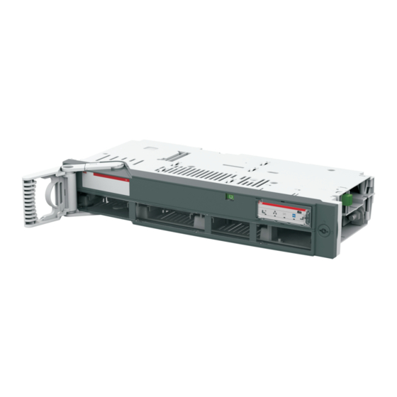
- Page 1 — I N S TA L L AT I O N I N S T R U C TI O N Switch Disconnector Fuse Slimline XRG1...
-
Page 2: Table Of Contents
— Table of contents Use of symbols Busbar overview Manual operation Motor operation Fuse replacement Accessory... -
Page 3: Use Of Symbols
SWITC H D ISCO N N EC TO R FU SE , XR G1 — Use of symbols Hazardous voltage Caution Warns about a situation where a hazardous Provides important information or warns voltage may cause physical injury to a per - about a situation that may have a detrimen - son or damage to equipment. - Page 4 If damage is evident, or there is vis - ible indication of rough handling, immedi- Warning ately file a damage claim with the transpor - tation company, and notify your local ABB sales office. HAZARD OF EQUIPMENT Do not remove the shipping package until OVERTURNING ready to install the switch.
- Page 5 SWITC H D ISCO N N EC TO R FU SE , XR G1 — Read these safety instructions carefully before using this product! HAZARD OF ELECTRIC SHOCK, EXPLOSION, OR ARC FLASH • Apply appropriate personal protective equipment and follow safe electrical work practices.
-
Page 6: Busbar Overview
SWITC H D ISCO NNEC TO R FUSE, XRG1 — Busbar overview 50/5-2p 50/5-3p 50/5-4p 50/10-2p 50/10-3p 50/10-4p... - Page 7 SWITC H D ISCO N N EC TO R FU SE , XR G1 — Busbar overview 185/10-2p 77.5 185/10-3p 77.5 185/10-4p 97.5 77.5...
-
Page 8: Manual Operation
SWITC H D ISCO NNEC TO R FUSE, XRG1 — Manual operation 45°... -
Page 9: Motor Operation
SWITC H D ISCO N N EC TO R FU SE , XR G1 — Motor operation 45°... - Page 10 SWITC H D ISCO NNEC TO R FUSE, XRG1 — Motor operation Signal: >0.5 sec or permanent Close Open Front cover must be locked before operating...
- Page 11 SWITC H D ISCO N N EC TO R FU SE , XR G1 — Motor operation XRG1 MOT 24V DC ±1 volt 1,3A...
-
Page 12: Its
Ekip Connect, use the USB connector at the bottom side of the Ekip Display. The connection cable has to be the T&P cable kit( Order code : 1SDA066989R0001 ) The Ekip Connect software tool can be downloaded for free at: http://www.abb.com/abblibrary/ DownloadCente... - Page 13 SWITC H D ISCO N N EC TO R FU SE , XR G1 — Terminal Signal 24 VDC 24 V GND (0V) RS- 485 0V RS- 485 + (A) RS- 485 - (B) Multiplug If a termination resistor is needed, it must be fitted Strap here for Strap here for...
- Page 14 SWITC H D ISCO NNEC TO R FUSE, XRG1 Technical data for XR ITS2.1 and ITS2.D Input voltage limits Power supply 24 VDC±20% Power consumption Functional characteristics Voltage measuring range 10 - 900 VAC Measured current range 0 - 1,3 x In Measuring range temperature 0 - 127 ⁰C Measuring accuracy (Voltage and current)
-
Page 15: Efm
SWITC H D ISCO N N EC TO R FU SE , XR G1 — Red LED: One or more fuses as blown Green LED: All fuses are OK Diagram XR DC 110/500 EFM Diagram XR AC EFM... - Page 16 SWITC H D ISCO NNEC TO R FUSE, XRG1 — Application 280-880V 40-140 ±5%...
-
Page 17: Fuse Replacement
SWITC H D ISCO N N EC TO R FU SE , XR G1 — Fuse replacement 10Nm... -
Page 18: Accessory
SWITC H D ISCO NNEC TO R FUSE, XRG1 — Accessory Guide rail... - Page 19 SWITC H D ISCO N N EC TO R FU SE , XR G1 — Accessory Multiplug...
- Page 20 SWITC H D ISCO NNEC TO R FUSE, XRG1 — Accessory Contact extension 50 busbar:9Nm 185 busbar:20Nm 2,5Nm...
- Page 21 SWITC H D ISCO N N EC TO R FU SE , XR G1 — Accessory Adjust protecton sleeve so it starts close as possible to the transformer. When installing a single CT: · See wiring connecton table below and choose cables to use according to terminal where CT is installed (1,2,3) Tightening torque 30Nm ·...
- Page 22 SWITC H D ISCO NNEC TO R FUSE, XRG1 — Accessory A-meter 1 2 3 4 T2-I Pin 1 mark T2-K X3-2 insulation tube X3-6 A-S2 T2-K...
- Page 23 SWITC H D ISCO N N EC TO R FU SE , XR G1 — Accessory Auxiliary switch...
- Page 24 SWITC H D ISCO NNEC TO R FUSE, XRG1 — Accessory Auxiliary switch Diagram for multiplug with motor EFM NO EFM NO/NC EFM NC C.T.No.1( ) Position feedback NO C.T.No.2 Field open Field closed Field common C.T.No.3 +24VDC Neutral(0V) Diagram for multiplug without motor EFM NO EFM NO/NC EFM NC...
- Page 25 SWITC H D ISCO N N EC TO R FU SE , XR G1 — Accessory Switch replacement tool...
- Page 26 SWITC H D ISCO NNEC TO R FUSE, XRG1...
- Page 27 — Contact us ABB Oy Smart Power P.O. Box 622 FI-65101 Vaasa Finland https://new.abb.com/contact-centers > Low Voltage Products and Systems © Copyright 2019 ABB. All rights reserved. Specifications subject to change without notice.