Table of Contents
Advertisement
Available languages
Available languages
Quick Links
LV Capacitor Bank APC
Installation, operation and maintenance instructions
Batteries automatiques de condensateurs basse tension APC
Instructions d'installation, d'utilisation et d'entretien
Pienjännitekompensointiparistot APC
Asennus-, käyttö- ja huolto-ohjeet
Kondensatorbank för lågspänning, APC
Instruktioner för installation, drift och underhåll
ABB
Advertisement
Chapters
Table of Contents

Summary of Contents for ABB APC Series
- Page 1 LV Capacitor Bank APC Installation, operation and maintenance instructions Batteries automatiques de condensateurs basse tension APC Instructions d’installation, d’utilisation et d’entretien Pienjännitekompensointiparistot APC Asennus-, käyttö- ja huolto-ohjeet Kondensatorbank för lågspänning, APC Instruktioner för installation, drift och underhåll...
- Page 2 Content English Page 4 Français Page 32 Suomi Sivu 60 Svenska Sid 88 APC - Content...
- Page 3 While all care has been taken to ensure that the information contained in this publication is correct, no responsibility can be accepted for any inaccuracy. The Company reserves the right to alter or modify the information contained herein at any time in the light of technical or other developments.
-
Page 4: Table Of Contents
Table of contents 1. Read this first ......................7 1.1. About this instruction manual ......................7 1.2. Safety ............................... 7 1.3. APC types ............................7 1.4. Inspection on reception ........................7 1.5. Guarantee ............................8 1.6. Storage............................. 8 1.7. Handling ............................8 1.8. - Page 5 7. Appendices ......................29 7.1. Technical specifications ......................... 29 7.2. Dimensions and weights ........................ 30 APC - Table of contents...
- Page 6 Table of figures Figure 1.1. APCM and APCR setting upright..................... 8 Figure 2.1. APC types ............................9 Figure 2.2. APCL2 of 125kvar/400V ........................9 Figure 2.3. APCM2 of 400kvar/400V ......................... 9 Figure 2.4. APCR of 300kvar/400V........................9 Figure 2.5. Example of a front face and rear face (APCM module)..............10 Figure 2.6.
-
Page 7: Read This First
Inspection on reception Make sure that the packaging has not been damaged in transit. Any loss or damage should be notified immediately to your closest local ABB agent. The small boxes (APCL1) are delivered upright. The big boxes (APCL2) are delivered on their side and 2 units maximum can be stacked one on top of the other for transit and storage. -
Page 8: Guarantee
Before applying voltage, make an electric insulation test of 2.5 kV between the earth and the short-circuited phases. Any damage resulting of this test should be notified immediately to your closest local ABB agent. WARNING: End this test by removing the short circuit of the phases. -
Page 9: Apc Description
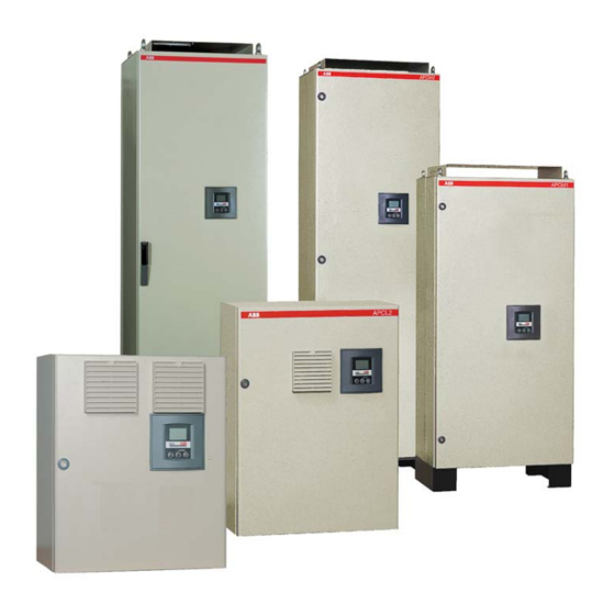
2. APC description APCR APCM2 APCM1 APCL2 APCL1 Figure 2.1. APC types Figure 2.3. APCM2 of 400kvar/400V Figure 2.2. APCL2 of 125kvar/400V LVCS capacitors RVC controller * UA type contactors Power cables connections HRC fuses Fan(s) Control circuit fuses Current transformer connection * Fan supply ** Reactors modules Remarks:... -
Page 10: Power Modules
2.1. Power modules Figure 2.5. Example of a front face and rear face (APCM module) Figure 2.6. Example of a front face and rear face (APCR module) 1 Fuses 2 Contactors 3 Capacitors 4 Reactors 2.2. Ventilation system APCL2, APCM1, APCM2 and APCR are provided with one or several fans. APCL1 is provided with air grids allowing natural ventilation. -
Page 11: Thermistor
2.2.1. Thermistor Each fan is of DC type and is equipped with its own thermistor. This thermistor will adapt the speed of the fan (“variofan” type) to the APC internal temperature. This fan operates from a 30°C temperature and delivers a maximum airflow for a 50°C temperature. 2.2.2. -
Page 12: Installation
3.2. Harmonics The installation of capacitors on networks disturbed by harmonics may require special precautions especially when there is a risk of resonance. Consult your closest local ABB agent if it is the case. 3.3. Fixation 3.3.1. APCL1 and APCL2 boxes Fix the boxes on the wall by means of the fixation kit provided for this purpose. -
Page 13: Electrical Diagram
Electrical diagram Figure 3.2. Electrical diagram Regarding the standard wiring of the ABB controllers, the voltage reference for the controllers is taken from L2 and L3 phases and the current transformer is sited on the L1 phase. If the current transformer is sited on another phase, it’s useless to modify the voltage and current connections since the APC bank is provided with an ABB controller with automatic adaptation to network phase-rotation and CT terminals. -
Page 14: Power Cables Connection
TO FEEDER TO LOAD TO FEEDER TO LOAD BANK1 BANK2 BANK1 BANK2 Figure 3.3. Connection of several banks in parallel The switching delay time of each master unit must slightly differ from the other ones. If the controllers are set to normal mode, we recommend using a switching time delay difference of 1 sec. (e.g. -
Page 15: Apcm1, Apcm2 And Apcr Cubicles
APCL1 APCL2 Figure 3.4. Power cables connection to the incoming power terminals for boxes 3.4.3.2. APCM1, APCM2 and APCR cubicles The APCM and APCR cubicles are available in bottom or top cable entry. By default, the bottom cable entry is applied. The plate at the bottom left of the cubicle is provided to allow cable entry (see Figure 3.1.) In case of top cable entry, use the two other plates at the top of the cubicle. -
Page 16: Figure 3.6. Ct Connection And Release Contact
Gray jumper to short-circuit the CT secondary winding Power release contact remote control Figure 3.6. CT connection and release contact When a multi ratio split core C.T. is used the appropriate ratio is selected by connecting either S2 or S3 or S4 to terminal marked . -
Page 17: Slave (Aux) To Master (Pil) Unit Connection (For Master Unit + Slave Unit Configuration)
3.4.5. Slave (AUX) to master (PIL) unit connection (for master unit + slave unit configuration) In a master unit + slave unit configuration an interconnection cable must be installed between the units. This cable is factory wired in the slave unit and allows a full control of the slave unit from the master unit. Note that only one slave unit can be added to each master unit and the slave unit must be of the same type (APCL2 with APCL2, APCM2 with APCM2 and APCR with APCR). -
Page 18: Master (Pil) Apcl2 Wiring
Depending on the type of the bank, pass the cable inside the right hand side raceway (APCL2 and APCR) or fix it along the central plate (APCM2). Please refer to Figure 3.10. APCL2 APCM2 APCR Figure 3.10. Interconnection cable location 3.4.5.1. -
Page 19: Master (Pil) Apcr Wiring
Special features connection Special features connection PF controller connection (terminal labels: X, 15, A) Figure 3.12. Master APCM2 wiring Please revert to the schematic diagrams fitted with the bank for exact label of the wires. 3.4.5.3. Master (PIL) APCR wiring The cable is divided in two main parts: the step control (to the PF controller) and special features (to a dedicated terminal). -
Page 20: Easy Commissioning
4. Easy commissioning 1. With the equipment isolated from the supply check tightness of all connections, earth bonding, fuses, free movement of contactors. 2. Check that the requirements for the cable cross section and the fuses are respected with regard to the total bank power. -
Page 21: Figure 4.2. View Of The Target Cos Φ Setting
7. Setting of the target cos ϕ Press the Mode button once to activate the manual setting of the target cos ϕ. The already programmed value is displayed. If the RVC has never been programmed before, “ ” appears on the LCD display. ϕ... -
Page 22: Figure 4.5. View Of The Protections Parameters
Figure 4.5. View of the Protections parameters Once in AUTO Mode, the RVC automatically switches on the necessary steps to reach the programmed ϕ. target cos ϕ The actual cos appears on the LCD display. Note: a negative cos ϕ indicates that the load is re-injecting reactive power on the network. The RVC continues to work normally. -
Page 23: Front View
4.1. Front view A. LCD display 1. Activated outputs 6. Demand for switching on or off capacitor steps 2. Overtemperature indication 7. Inductive PF 3. Disconnection indication 8. Capacitive PF 4. User settable parameters 9. Alarm indication 5. Modes 10. Measurement unit 11. -
Page 24: Rear View
4.2. Rear view Figure 4.7. Rear view of the RVC k, l: leads of the current transformer L2, L3: 2 of the 3 phases (not monitored by the CT) M1, M2: leads of the normally open contact output relay common source 1-12: outputs APC - Chapter 4. -
Page 25: Troubleshooting
5. Troubleshooting Most of the APC operating problems may be detected thanks to the controller. Refer to the troubleshooting paragraph of the controller instruction manual. If the controller is connected but doesn’t display anything, check the voltage presence to its leads. If there is no voltage, this may be explained by: a discontinuity of the circuit (check the wiring, fuses, etc…) an overtemperature of 60°C having caused the opening of the temperature probe and thus the power... -
Page 26: Maintenance
6. Maintenance Ensure safety procedures are completed as earlier stated. 6.1. APC maintenance Your capacitors are an investment, protect them by regular maintenance. Annual maintenance should include: Remove dust deposits, clean all parts, paint metalwork as required; Check fuse condition; Check contactor condition and operation –... -
Page 27: Figure 6.2. Disconnection Of The Contactor And The Protection Fuses
Disconnect the 2 contactor control cables Disconnect protection fuses (∅ M8) Disconnect the 3 input cables of the contactor Disconnect protection fuses (∅ M8) Figure 6.2. Disconnection of the contactor and the protection fuses Remove the supporting plate Withdraw the capacitor module by unscrewing the 4 screws Figure 6.3. -
Page 28: Access To Reactors
6.3. Access to reactors Withdraw the capacitor module Remove the protection plate Remove the protection plate by unscrewing the 4 screws Cut the flexible cable locks Easy access to reactor and connections to free the power cables Figure 6.4. Access to reactors APC - Chapter 6. - Page 29 7. Appendices 7.1. Technical specifications Nominal voltage and frequency: Acceptable overloads: 230, 400V – 50Hz (standard range), Overvoltage tolerance: 10% max. intermittently. 240, 480V – 60Hz (standard range), Overcurrent tolerance: 30% permanently. 400V – 50Hz (reinforced range rated at 474 V), Temperature range: -25°C / class D according to IEC 400, 415, 525, 690V –...
-
Page 30: Figure 7.1. Apc Dimensions And Weights
7.2. Dimensions and weights APCL1*: max. 26kg APCL2*: max. 42kg APCM1: max. 100kg *thickness of the air grid (25mm) not included. APCM2: max. 175kg APCR: max. 500kg Figure 7.1. APC dimensions and weights APC - Chapter 7. Appendices... - Page 32 Table des matières 1. A lire en premier ......................35 1.1. Objectif du manuel d’instructions ....................35 1.2. Sécurité ............................35 1.3. Présentation ........................... 35 1.4. Inspection à la réception du matériel ..................... 35 1.5. Garantie............................36 1.6. Entreposage ........................... 36 1.7.
- Page 33 7. Annexes ........................57 7.1. Caractéristiques techniques......................57 7.2. Dimensions et poids ........................58 APC - Table des matières...
- Page 34 Table des figures Figure 1.1. Redressement APCM et APCR ..................... 36 Figure 2.1. Types d’APC ..........................37 Figure 2.2. APCL2 de 125kvar/400V ....................... 37 Figure 2.3. APCM2 de 400kvar/400V ......................37 Figure 2.4. APCR de 300kvar/400V......................... 37 Figure 2.5. Exemple d’une vue de face et d’une vue de dos (module APCM) ..........38 Figure 2.6.
-
Page 35: A Lire En Premier
Inspection à la réception du matériel Vérifiez l’emballage et assurez-vous que celui-ci n’a subi aucun choc ni dommage pendant le transport. Toute perte ou dommage doit être signalée immédiatement à votre agent local ABB le plus proche. Les petits coffrets (APCL1) sont livrés debout. -
Page 36: Garantie
Avant mise sous tension, réalisez un test d’isolation électrique de 2,5 kV entre la terre (la masse) et les phases court-circuitées. Tout dégât résultant de ce test doit être signalé immédiatement à votre agent local ABB le plus proche. ATTENTION: Terminez ce test en enlevant le court-circuit des phases. -
Page 37: Description De L'apc
2. Description de l’APC APCR APCM2 APCM1 APCL2 APCL1 Figure 2.1. Types d’APC Figure 2.3. APCM2 de 400kvar/400V Figure 2.2. APCL2 de 125kvar/400V Condensateurs LVCS Régulateur RVC * Contacteurs type UA Raccordement des câbles de puissance Fusibles HPC Ventilateur(s) Fusibles protection circuit commande... -
Page 38: Modules De Puissance
2.1. Modules de puissance Figure 2.5. Exemple d’une vue de face et d’une vue de dos (module APCM) Figure 2.6. Exemple d’une vue de face et d’une vue de dos (module APCR) 1 Fusibles 2 Contacteurs 3 Condensateurs 4 Selfs 2.2. -
Page 39: Thermistance
2.2.1. Thermistance Chaque ventilateur est de type DC et est équipé de sa propre thermistance. Cette thermistance va faire varier la vitesse du ventilateur (type ‘’variofan’’) en fonction de la température interne de l’APC. Ce ventilateur fonctionne à partir d’une température de 30°C et délivre un débit maximal pour une température de 50°C. -
Page 40: Installation
Harmoniques L’installation de condensateurs sur des réseaux perturbés par des harmoniques peut nécessiter des précautions spéciales surtout s’il y a risque de résonance. Veuillez consulter votre agent local ABB le plus proche si tel était le cas. 3.3. Fixation 3.3.1. -
Page 41: Schéma Électrique De Principe
Figure 3.2. Schéma électrique de principe Selon le schéma de raccordement standard des régulateurs ABB, la référence de tension du relais est prise à partir des phases L2 et L3 et le transformateur d’intensité est placé sur la phase L1. -
Page 42: Raccordement Du Circuit De Puissance
ALIMENTATION CHARGES ALIMENTATION CHARGES BATTERIE 1 BATTERIE 2 BATTERIE 1 BATTERIE 2 Figure 3.3. Connexion de plusieurs batteries en parallèle Les délais d’enclenchement de chaque unité pilote devront être légèrement différents. Si les régulateurs travaillent en mode normal, nous recommandons d’utiliser une différence de délai d’enclenchement d’1 sec. -
Page 43: Armoires Apcm1, Apcm2 Et Apcr
APCL1 APCL2 Figure 3.4. Branchement de la puissance des coffrets 3.4.3.2. Armoires APCM1, APCM2 et APCR Les armoires APCM et APCR sont disponibles pour une alimentation par le bas ou par le haut. Par défaut, l’alimentation est par le bas. La plaque dans la partie inférieure gauche de l’armoire permet le passage du câble (voir Figure 3.1.) Dans le... - Page 44 Cavalier gris permettant de court-circuiter le TI Contact de délestage pour commande à distance Figure 3.6. Connexion du TI et contact de délestage Lorsqu’un transformateur multi-rapport est utilisé, le rapport approprié est sélectionné en branchant S2 ou S3 ou S4 à la borne repérée .
-
Page 45: Connexion De L'unité Auxiliaire (Aux) À L'unité Pilote (Pil) (Pour La Configuration Pilote + Auxiliaire)
Lorsqu’un transformateur totalisateur est utilisé ou lorsque le transformateur ne contrôle qu’une charge partielle (c’est-à-dire par exemple deux câbles en parallèle par phase avec le transformateur sur un seul câble), le courant total du système qui donne 5A dans la bobine amperemétrique du relais est utilisé pour calculer le réglage du relais. -
Page 46: Connexion À L'unité Pilote (Pil) Apcl2
En fonction du type de batterie, passez le câble dans le rail situé sur le flan intérieur droit de l’unité pilote (APCL2 et APCR) ou fixez-le le long du rail central (APCM2). Veuillez vous référer à la Figure 3.10. APCL2 APCM2 APCR Figure 3.10. -
Page 47: Connexion À L'unité Pilote (Pil) Apcr
Connexion des fonctions spéciales Connexion des fonctions spéciales Connexion du régulateur (bornes: X, 15, A) Figure 3.12. Connexion à l’unité pilote APCM2 Veuillez vous référer aux diagrammes fournis dans la batterie pour l’étiquetage précis des câbles. 3.4.5.3. Connexion à l’unité pilote (PIL) APCR Le câble est divisé... -
Page 48: Mise En Service Facile
4. Mise en service facile 1. Le matériel étant isolé de l’alimentation, vérifiez que toutes les connexions sont bien serrées, contrôlez la mise à la terre, les fusibles, le libre mouvement des contacteurs. 2. Vérifiez que la batterie est raccordée avec des câbles et des fusibles appropriés à la puissance totale de la batterie. - Page 49 7. Facteur de puissance cible Appuyez sur le bouton Mode afin d’activer le paramétrage manuel du cos ϕ. Le cos ϕ cible est affiché. Si le RVC n’a jamais été programmé auparavant, la valeur “ ” s’affiche sur l’écran. ϕ Figure 4.2.
- Page 50 Figure 4.5. Ecrans des paramètres de protection Arrivé dans le Mode AUTO, le RVC va automatiquement enclencher les gradins nécessaires afin d’atteindre le cos ϕ cible programmé. Le cos ϕ réel apparaît sur l’écran à cristaux liquides. Remarque : un cos ϕ négatif indique que la charge injecte de la puissance réactive sur le réseau. Le RVC continue à...
-
Page 51: Panneau Frontal
4.1. Panneau frontal A. Ecran à cristaux liquides 1. Sorties actives 7. Facteur de puissance inductif 2. Indicateur de surtempérature 8. Facteur de puissance capacitif 3. Indicateur de déconnexion 9. Indicateur d’alarme 4. Paramètres programmable par l’utilisateur 10. Unité de mesure 5. -
Page 52: Panneau Arrière Et Disposition Des Connecteurs
4.2. Panneau arrière et disposition des connecteurs Réseau d’alimentation Charge Figure 4.7. Panneau arrière du RVC k, l: transformateur de courant L2, L3: 2 des 3 phases (non contrôlées par le TI) M1, M2: contact d’alarme (normalement ouvert) commun des connecteurs de sorties 1-12: sorties APC - Chapitre 4. -
Page 53: Détection De Pannes
5. Détection de pannes La plupart des problèmes de fonctionnement de la batterie de condensateurs peuvent être détectés grâce au régulateur. Veuillez vous référer au paragraphe “détection de pannes” du manuel d’instruction du régulateur. Si le régulateur est connecté mais n’indique rien à l’écran, il y a lieu de vérifier la présence de tension à ses bornes. -
Page 54: Entretien
6. Entretien Vérifiez que les procédures de sécurité mentionnées au début de ce manuel d’instructions ont bien été suivies. 6.1. Maintenance de l’APC Vos condensateurs sont un investissement, protégez-les par un entretien régulier. L’entretien annuel doit comprendre : l’enlèvement des dépôts de poussière, le nettoyage de toutes les pièces, les retouches (peinture) de parties métalliques si nécessaire ;... - Page 55 Déconnectez les 2 câbles de la bobine du contacteur Déconnectez les fusibles de protection (∅ M8) Déconnectez les 3 câbles d’entrée du contacteur Déconnectez les fusibles de protection (∅ M8) Figure 6.2. Déconnexion du contacteur et des fusibles de protection Enlevez les 4 vis de maintien de la tôle de Retirez le module condensateur support du module condensateur...
-
Page 56: Accès Aux Selfs De L'apcr
6.3. Accès aux selfs de l’APCR Retirez le module condensateur Retirez la tôle de protection Retirez les 4 vis de maintien de la tôle de protection Libérez les câbles en coupant Accès aisé aux connexions et à la self les colliers de serrage Figure 6.4. - Page 57 7. Annexes 7.1. Caractéristiques techniques Tension nominale et fréquence: Tests en tension : 2.15 X Un entre bornes pendant 230, 400V – 50Hz (condensateurs standards), 10 s. à la fréquence nominale (supérieur à EN 60831- 240, 480V – 60Hz (condensateurs standards), 1&2).
- Page 58 7.2. Dimensions et poids APCL1*: max. 26kg APCL2*: max. 42kg APCM1: max. 100kg *épaisseur de la grille d’aération (25mm) non comprise. APCM2: max. 175kg APCR: max. 500kg Figure 7.1. Dimensions et poids des APC APC - Chapitre 7. Annexes...
- Page 60 Sisällysluettelo 1. Lue tämä ensin ......................63 1.1. Yleistä............................. 63 1.2. Turvallisuus ............................ 63 1.3. APC-tyypit ............................63 1.4. Vastaanottotarkastus........................63 1.5. Takuu ............................. 63 1.6. Säilytys ............................64 1.7. Käsittely............................64 1.8. Eristystesti ............................64 2. APC - kuvaus ......................65 2.1.
- Page 61 7. Liitteet........................85 7.1. Tekniset erittelyt ..........................85 7.2. Mitat ja painot ..........................86 APC - Sisällysluettelo...
- Page 62 Kuvat Kuva 1.1. APCM ja APCR nosto pystyasentoon ..................... 64 Kuva 2.1. APC - kuvaus ........................... 65 Kuva 2.2. APCL2, 125kvar/400V ........................65 Kuva 2.3. APCM2, 400kvar/400V ........................65 Kuva 2.4. APCR, 300kvar/400V........................65 Kuva 2.5. Kuva edestä ja takaa (APCM-moduuli) ................... 66 Kuva 2.6.
-
Page 63: Lue Tämä Ensin
1.4. Vastaanottotarkastus Varmista, että pakkaus ei ole vahingoittunut kuljetuksessa. Kaikista vahingoista ja puutteista tulee ilmoittaa välittömästi ABB Oy:n Kotimaan tuotemyyntiin. Pienet kotelot (APCL1) toimitetaan pystyasennossa. Suuret kotelot (APCL2) toimitetaan kyljellään ja korkeintaan kaksi yksikköä voidaan asettaa päällekkäin kuljetuksen ja varastoinnin ajaksi. -
Page 64: Säilytys
1.8. Eristystesti Tee 2,5 kV:n eristystesti maan ja oikossuljettujen vaiheiden välillä ennen jänniteen syöttöä. Mikäli laite vioittuu testin aikana, ilmoita siitä välittömästi ABB Oy:n Kotimaan tuotemyyntiin. VAROITUS: Testi lopetetaan poistamalla vaiheiden väliltä oikosulku. APC - Luku 1. Lue tämä ensin... -
Page 65: Apc - Kuvaus
2. APC - kuvaus APCR APCM2 APCM1 APCL2 APCL1 Kuva 2.1. APC - kuvaus Kuva 2.3. APCM2, 400kvar/400V Kuva 2.2. APCL2, 125kvar/400V LVCS kondensaattorit Loistehon säädin * UA-tyypin kontaktorit Syöttökaapeliliitännät HRC-varokkeet Tuuletin (tuulettimet) Ohjauspiirin varokkeet Virtamuuntajaliitäntä * Tuulettimen syöttö ** Estokelamoduulit Huom: *: vain isäntäyksikössä. -
Page 66: Syöttömoduulit
2.1. Syöttömoduulit Kuva 2.5. Kuva edestä ja takaa (APCM-moduuli) Kuva 2.6. Kuva edestä ja takaa (APCR-moduuli) 1 Varokkeet 2 Kontaktorit 3 Kondensaattorit 4 Estokelat 2.2. Tuuletusjärjestelmä APCL2, APCM1, APCM2 ja APCR on varustettu yhdellä tai useammalla tuulettimella. APCL1 on varustettu luonnollisen ilmanvaihdon tuuletusritilöin. APCL1 APCL2 APCM1... -
Page 67: Termistori
2.2.1. Termistori Tuulettimet ovat tasavirtatuulettimia ja ne on varustettu omin termistorein. Termistori sovittaa tuulettimen nopeuden (“vario”-tyypin tuuletin) APC-pariston sisäiseen lämpötilaan. Tuuletin alkaa toimia 30°C asteen lämpötilassa ja sen ilmavirta on maksimissaan 50°C asteen lämpötilassa. 2.2.2. Lämpötila-anturi E Kaikki APC-kompensointiparistot varustetaan myös lämpötila-anturilla säätimen virran katkaisemiseksi. Mikäli lämpötila nousee yli 60°C, kompensointiparisto kytkeytyy pois automaattisesti. -
Page 68: Asennus
A Korjaaviin toimenpiteisiin tulee ryhtyä, mikäli ympäristön lämpötila laskee alle -5°C tai ylittää 40°C. 3.2. Yliaallot Kondensaattoreiden asennus yliaaltoisiin verkkoihin saattaa vaatia erityistoimenpiteitä varsinkin, jos on olemassa resonanssivaara. Tällaisessa tapauksessa ota yhteys ABB Oy:n Kotimaan tuotemyyntiin Pääsääntö on, että yliaaltopitoisiin verkkoihin asennetaan estokelaparisto (APCR). 3.3. Kiinnitys 3.3.1. -
Page 69: Periaatekaavio
Periaatekaavio Kuva 3.2. Periaatekaavio ABB:n vakiosäätimissä jännitemittaus otetaan vaiheista L2 ja L3 ja virtamuuntaja asennetaan vaiheeseen Jos virtamuuntaja sijoitetaan johonkin muuhun vaiheeseen kuin L1, ei jännite- ja virtaliitoksia tarvitse muuttaa, koska APC-paristo on varustettu ABB-säätimellä, joka sopeuttaa sen automaattisesti verkon vaihekiertoon ja virtamuuntajaliittimiin. -
Page 70: Syöttökaapeliliitäntä
Laitteiden nimellisvirran on oltava vähintään 1,5 kertainen kondensaattorin arvoihin verrattuna. On huomioitava, että mikäli varokkeita käytetään, on niiden oltava mitoitettu kaapelien suojaamiseksi ja niiden virta-arvojen on oltava vähintään 1,6 kertainen kondensaattorin nimellisvirtaan verrattuna. Jos sulakkeiden mitoitus on epäselvä, ota yhteyttä ABB Oy:n Kotimaan tuotemyyntiin. 3.4.3.1. APCL1- ja APCL2-kotelot APCL1 ja APCL2 ovat tehtaalla asennettuja ja kaapeleiden sisäänviennit on järjestetty esi-irrotettujen... -
Page 71: Apcm1, Apcm2 Ja Apcr Kennot
APCL1 APCL2 Kuva 3.4. Syöttökaapeliliitäntä syöttöliittimiin (APCL1 ja APCL2) 3.4.3.2. APCM1, APCM2 ja APCR kennot APCM ja APCR kennoihin voi syöttö tulla joko ylhäältä tai alhaalta. Levy kennon pohjassa vasemmalla sallii syötön sisäänviennin (katso kuva 3.1.) Kun sisääntulo on ylähäältä käytetään kahta muuta levyä... -
Page 72: Kuva 3.6. Vm Liityntä Ja Laukaisukosketin
Harmaa oikosulkusilta virtamuuntajan toisiokäämin oikosulkemiseen Kosketin, jolla generaattori voi kytkeä pariston irti verkosta Kuva 3.6. VM liityntä ja laukaisukosketin Kun käytetään virtamuuntajaa, jossa on useita muuntosuhteita, muuntosuhde valitaan kytkemällä joko S2 tai S3 tai S4 l–liittimeen. Muuntosuhde on valittava mahdollisimman lähelle syöttökuormaa. Kuva 3.7. -
Page 73: Orja (Aux) Isäntä (Pil) Yksikön Liitäntä (Isäntä-Orjasovite)
3.4.5. Orja (AUX) isäntä (PIL) yksikön liitäntä (isäntä-orjasovite) Orjaisäntäliitynnässä asennetaan yksiköiden välille liityntäkaapeli. Tämä kaapeli on tehtaalla asennettu orjayksikköön ja mahdollistaa yksikön ohjauksen. Vain yksi orjayksikkö on mahdollista kytkeä isäntään ja yksiköiden täytyy olla samaa paristotyyppiä. Kytkentäohjeet: Vapauta orjayksikössä oleva kaapeli kennon pohjalta. Irroita musta tiivisterengas pohjalevystä. Huomaa että... -
Page 74: Isäntä Apcl2 Johdotus
APCL2 APCM2 APCR Kuva 3.10. Yhdyskaapelin asennus 3.4.5.1. Isäntä APCL2 johdotus Kaapeli on jaettu kolmeen osaan: DC-syöttö tuulettimelle, portaiden säätö ja erikoistoiminnot Erikoistoiminnot liityntä DC-syöttö liityntä Säätöliityntä (liittimet X, 15) Kuva 3.11. Isäntä APCL2 johdotus Varmista kaapelin merkkaus piirikaaviosta. 3.4.5.2. Isäntä... -
Page 75: Isäntä Apcr Johdotus
3.4.5.3. Isäntä APCR johdotus Kaapeli on jaettu kahteen osaan: portaiden säätö ja erikoistoiminnot. Erikoistoiminnot Erikoistoiminnot Säätöliitynnät (liittimet X,15,A) Kuva 3.13. Isäntä APCR johdotus Varmista kaapelin merkkaus piirikaaviosta sekä tarkista että kaapeli on kiinnitetty paristoon kunnolla. 3.4.6. Maadoitusliitäntä APCL-koteloiden maadoitusliitännät tehdään ruuvin avulla (∅ M6), joka on hitsattu APCL-kotelon sisään oikeaan alakulmaan. -
Page 76: Käyttöönotto
4. Käyttöönotto 1. Kun laite ei ole verkossa, tarkasta liitosten kireydet, maadoitus, varokkeet, kytkinten vapaa liikkuminen. 2. Tarkasta, että kaapeleiden poikkipinta-alat ja varokkeet on oikein mitoitettu kompensointipariston kokonaistehoon nähden. 3. Tarkasta, että virtamuuntaja on asennettu kunnolla L1-vaiheeseen eli ainoaan vaiheeseen, mistä ei oteta jännitettä... -
Page 77: Kuva 4.2. Tavoitetehokertoimen Asettelu
7. Tavoitetehokertoimen asettelu Paina Mode-painiketta kerran tehokertoimen (cos ϕ) käsinasettelun aktivoimiseksi. Valmiiksiohjelmoitu arvo ilmestyy näyttöön. Ellei RVC:tä ole ohjelmoitu aiemmin, näyttöön ilmestyy “ ”. Kuva 4.2. Tavoitetehokertoimen asettelu Aseta tavoitearvo cos ϕ fpainamalla joko - tai + painiketta. osoitaa induktiivista ja kapasitiivista tehokerrointa. - Page 78 Figure 4.5. Suojaparametrien näyttö Kun AUTO-tila on asetettu, RVC kytkee automaattisesti tarvittavat portaat päälle ohjelmoidun tehoarvon saavuttamiseksi. Todellinen cos ϕ ilmestyy näyttöön. Huom. Negatiivinen cos ϕ osoittaa, että kuorma syöttää loistehoa verkkoon. RVC jatkaa toimintaa normaalisti. Tärkeää Minimikytkentäviive APC portaiden välillä on 40 sekuntia. Jos tämä...
-
Page 79: Näyttö Edestä
4.1. Näyttö edestä A. LCD-näyttö 1. Aktivoidut lähdöt 6. Kondenaattoriportaiden päälle- tai poiskytkentä 2. Lämpötilan ylittymisen ilmaisin 7. Induktiivinen tehokerroin 3. Erotuksen ilmaisu 8. Kapasitiivinen tehokerroin 4. Käyttäjän aseteltavissa olevat parametrit 9. Hälytyksen ilmaisu 5. Moodit 10. Mittausyksikkö 11. Viite step 8 tässä luvussa Kuva 4.6. -
Page 80: Näyttö Takaa
4.2. Näyttö takaa Kuva 4.7. Näyttö takaa k, l: virtamuuntajan johtimet L2, L3: 2 / 3 vaiheesta (ei virtamuuntajan valvomat) M1, M2: normaalisti avoimet hälytyskoskettimet lähtöreleiden yhteinen napa 1-12: lähdöt APC - Luku 4. Käyttöönotto... -
Page 81: Vianetsintä
5. Vianetsintä Useimmat APC-pariston toimintaviat on mahdollista löytää säätimen ansiosta. Lue säätimen käyttöohjeen vianetsintää koskeva kohta. Jos säädin on kytketty, mutta näytössä ei näy mitään, tarkasta jännitteisyys. Mikäli jännitettä ei ole, tämä saattaa johtua seuraavista syistä: piiri poikki (tarkasta johdot, varokkeet jne.) yli 60°C lämpötila on aiheuttanut lämpötilanilmaisimen avautumisen ja virran katkeamisen. -
Page 82: Huolto
6. Huolto Tarkista, että edelläkuvatut turvatoimet on suoritettu ennen huoltotöihin ryhtymistä. 6.1. APC-pariston huolto Kondensaattorit ovat investointi, siksi niitä kannattaa huoltaa säännöllisin väliajoin. Vuosihuollossa tulee tehdä seuraavat asiat: Poista pöly, puhdista kaikki osat, korjausmaalaa metalliosat mikäli tarpeellista; Tarkasta varokkeiden kunto; Tarkasta kontaktoreiden kunto ja toiminta, vaihda tarvittaessa;... -
Page 83: Kuva 6.2. Kontaktorin Ja Sulakkeiden Irroitus
Irrota kaksi kontaktori- ohjauskaapelia Irrota kaapelit varokealustasta (∅ M8) Irrota kolme kontaktorin of syöttökaapelia Irrota kaapelit varokealustasta (∅ M8) Kuva 6.2. Kontaktorin ja sulakkeiden irroitus Poista tukilevy irrottamalla Vedä kondensaattorimoduuli ulos neljä ruuvia Kuva 6.3. Kondensaattorimoduulin irroitus APC - Luku 6. Huolto... -
Page 84: Estokelojen Vaihto
6.3. Estokelojen vaihto Vedä ulos kondensaattorimoduuli Poista suojalevy Poista suojalevy irrottamalla neljä ruuvia Katkaise joustavat kaapelilukot syöttökaa- Pääsy estokelalle ja liittimille on helppoa peleiden vapauttamiseksi Kuva 6.4. Estokelojen vaihto APC - Luku 6. Huolto... - Page 85 7. Liitteet 7.1. Tekniset erittelyt Nimellisjännite ja taajuus: Sallitut ylikuormat: 230, 400V – 50Hz (normaali alue), Ylijännitesieto: maks. 10% ajoittain. 240, 480V – 60Hz (normaali alue), Ylivirtasieto: 30% jatkuvasti. 400V – 50Hz (vahvistettu 474 V), Lämpötila-alue: -25°C / class D according to IEC 400, 415, 525, 690V –...
-
Page 86: Kuva 7.1. Mitat Ja Painot
7.2. Mitat ja painot APCL1*: max. 26kg APCL2*: max. 42kg APCM1: max. 100kg * ei sisällä tuuletusritilän paksuutta (25mm). APCM2: max. 175kg APCR: max. 500kg Kuva 7.1. Mitat ja painot APC - Luku 7. Liitteet... - Page 88 Innehållsförteckning 1. Läs detta först......................91 1.1. Om den här manualen........................91 1.2. Säkerhet ............................91 1.3. APC-typer............................91 1.4. Mottagningsinspektion........................91 1.5. Garanti............................91 1.6. Lagring ............................92 1.7. Hantering............................92 1.8. Test av den elektriska isoleringen....................92 2. APC-beskrivning......................93 2.1.
- Page 89 7. Bilagor ........................113 7.1. Tekniska specifikationer ....................... 113 7.2. Mått och vikter ..........................114 APC – Innehållsförteckning...
- Page 90 Figurförteckning Figur 1.1. Resning av APCM och APCR......................92 Figur 2.1. APC-typer ............................93 Figur 2.2. 125kvar/400V APCL2 ........................93 Figur 2.3. 400kvar/400V APCM2 ........................93 Figur 2.4. 300kvar/400V APCR........................93 Figur 2.5. Exempel på framsida och baksida (APCM-modul)................94 Figur 2.6.
-
Page 91: Läs Detta Först
Mottagningsinspektion Kontrollera att emballaget inte har skadats vid transporten. Saknat gods eller skador ska omedelbart meddelas till närmaste ABB-återförsäljare. De små lådorna (APCL1) levereras stående. De stora lådorna (APCL2) levereras liggande och maximalt två enheter kan staplas på varandra vid transport och lagring. -
Page 92: Lagring
Innan spänningen kopplas in ska den elektriska isoleringen testas med 2,5 kV mellan jord och de kortslutna faserna. Skador som uppstår vid detta test ska omedelbart meddelas till närmaste ABB-återförsäljare. VARNING! Avsluta detta test genom att ta bort kortslutningen mellan faserna. -
Page 93: Apc-Beskrivning
2. APC-beskrivning APCR APCM2 APCM1 APCL2 APCL1 Figur 2.1. APC-typer Figur 2.3. 400kvar/400V APCM2 Figur 2.2. 125kvar/400V APCL2 LVCS-kondensatorer RVC-regulator * Kontaktorer av UA-typ Kraftkabelanslutningar HRC-säkringar Fläkt(ar) Säkringar för styrkrets Transformatoranslutning * Fläktmatning ** Reaktormoduler Anm.: *: endast i masterskåp. **: ej för slav APCL2. -
Page 94: Effektmoduler
2.1. Effektmoduler Figur 2.5. Exempel på framsida och baksida (APCM-modul) Figur 2.6. Exempel på framsida och baksida (APCR-modul) 1 Säkringar 2 Kontaktorer 3 Kondensatorer 4 Reaktorer 2.2. Ventilationssystem APCL2, APCM1, APCM2 och APCR är utrustade med en eller flera fläktar. APCL1 är utrustad med luftgaller som tillåter naturlig ventilation. -
Page 95: Termistor
2.2.1. Termistor Varje fläkt är av DC-typ och utrustad med en egen termistor. Denna termistor anpassar fläktens hastighet (“variofan-typ") efter den invändiga temperaturen i APC. Fläkten startar vid 30°C och ger maximalt luftflöde vid 50°C. 2.2.2. Temperatursond Varje APC-skåp är också utrustat med en temperatursond som slår av regulatorens strömtillförsel. Om temperaturen stiger till cirka 60°C kopplas hela APC-banken automatiskt bort. -
Page 96: Installation
Särskilda åtgärder måste vidtas vid omgivningstemperaturer ner till -5°C eller över 40°C. 3.2. Övertoner Installation av kondensatorer i nät som störs av övertoner kan kräva särskilda försiktighetsåtgärder, särskilt om det finns risk för resonans. Kontakta närmaste ABB-återförsäljare för råd om så är fallet. 3.3. Fastsättning 3.3.1. APCL1 och APCL2 Fäst lådorna i väggen med hjälp av den fästsats som tillhandahålls för ändamålet. -
Page 97: Elschema
L1-fasen. Om strömtransformatorn sitter på en annan fas behövs spännings- och strömanslutningarna inte ändras eftersom APC-banken har en ABB-regulator med automatisk anpassning till fasförskjutningen. Master-enheterna är förbereda för fjärrmanövrering som gör det möjligt att slå på och av hela APCbanken på... -
Page 98: Kraftkabelanslutning
TILL MATNING TILL LAST TILL LAST TILL MATNING BANK1 BANK2 BANK1 BANK2 Figur 3.3. Parallellkoppling av flera banker Omkopplingsfördröjningen för varje masterenhet måste skilja sig något från de övriga. Om regulatorerna står i normalläge rekommenderar vi 1 sekunds skillnad i omkopplingsfördröjning (t.ex. 40 s, 41 s, 42 s, …) Om regulatorerna står i integralläge rekommenderar vi minst 21 sekunders skillnad i omkopplingsfördröjning (t.ex. -
Page 99: Skåpen Apcm1, Apcm2 Och Apcr
APCL1 APCL2 Figur 3.4. Anslutning av kraftkablar till skåpens anslutningsskenor 3.4.3.2. Skåpen APCM1, APCM2 och APCR APCM- och APCR-skåpen kan fås med kabelgenomföring nedtill eller upptill. Kabelgenomföring nedtill är standard. Plåten nere till vänster i skåpet är till för att möjliggöra kabelgenomföring (se Figur 3.1) Vid kabelgenomföring upptill ska du använda de två... - Page 100 Grå jumper för kortslutning av transformatorns sekundärlindning Jumper för fjärrmanövrering Figur 3.6. Transformatoranslutning och frånslagskontakt Om en tångströmtransformator med olika omsättningar används väljs rätt omsättning genom att antingen S2, S3 eller S4 ansluts till det stift som är markerat . Transformatoromsättningen ska väljas så nära som möjligt för att passa matningslasten.
-
Page 101: Anslutning Av Slavenhet (Aux) Till Masterenhet (Pil) (För Konfiguration Med Masterenhet + Slavenhet)
3.4.5. Anslutning av slavenhet (AUX) till masterenhet (PIL) (för konfiguration med masterenhet + slavenhet) I en konfiguration med masterenhet + slavenhet måste en anslutningskabel installeras mellan enheterna. Denna kabel är fabriksinstallerad i slavenheten och möjliggör full kontroll över slavenheten från masterenheten. -
Page 102: Masterkoppling (Pil) Av Apcl2
Beroende på typ av bank leder du kabeln inuti banan på höger sida (APCL2 och APCR) eller fäster den vid mittplåten (APCM2). Se Figur 3.10. APCL2 APCM2 APCR Figur 3.10. Anslutningskabelns plats 3.4.5.1. Masterkoppling (PIL) av APCL2 Kabeln är indelad i tre huvuddelar: DC-matning för fläkten (till DC-strömförsörjningsenheten), stegkontrollen (till effektfaktor-regulatoren) och specialfunktioner (till ett särskilt stift). -
Page 103: Masterkoppling (Pil) Av Apcr
Anslutning för specialfunktioner Anslutning för specialfunktioner Anslutning för PF-styrenhet (plintmärkning: X, 15, A) Figur 3.12. Masterkoppling av APCM2 Se bankens kopplingsschema för kablarnas exakta märkning. 3.4.5.3. Masterkoppling (PIL) av APCR Kabeln är indelad i två huvuddelar: Stegkontrollen (till effektfaktor-regulatoren) och specialfunktioner (till ett särskilt stift). -
Page 104: Enkel Idrifttagning
4. Enkel idrifttagning 1. Medan utrustningen är isolerad från spänningsmatningen kontrollerar du fastsättningen av alla anslutningar, jordningen, säkringar och kontaktorernas rörlighet. 2. Kontrollera att kraven på kabelns tvärsnitt och säkringarna uppfylls med avseende på bankens totala effekt. 3. Kontrollera att transformatorn är korrekt placerad på fasledare L1, dvs. den enda fas där spänning till effektfaktor-regulatoren inte tas (effektfaktor-regulatoren ska anslutas mellan L2 och L3). - Page 105 7. Ange målvärde för cos ϕ Tryck en gång på knappen Mode för att aktivera den manuella inställningen av målvärdet för cos ϕ. Det redan programmerade värdet visas. Om RVC aldrig tidigare programmerats visas “ ” på LCD-displayen. ϕ Figur 4.2. Inställning av målvärde för cos Ange målvärde för cos ϕ...
- Page 106 Figur 4.5. Översikt av skyddsparametrar Väl i AUTO-läge slår RVC automatiskt på de steg som behövs för att nå det programmerade värdet för ϕ. ϕ Verkligt värde för cos visas på LCD-displayen. Obs! Ett negativt värde för cos ϕ indikerar att lasten matar in reaktiv kraft i nätet. RVC fortsätter att fungera normalt.
-
Page 107: Regulatorn - Vy Framifrån
4.1. Regulatorn - Vy framifrån A. LCD-display 1. Aktiverade utgångar 6. Behov av till- eller frånkoppling av kondensatorsteg 2. Övertemperaturindikering 7. Kapacitiv effektfaktor 3. Ifrånkopplingsindikering 8. Induktiv effektfaktor 4. Inställbara parametrar 9. Alarmindikering 5. Driftlägen 10. Mätenheter 11. Refererar till steg 8 i detta kapitel Figur 4.6. -
Page 108: Regulatorn - Vy Bakifrån
4.2. Regulatorn - Vy bakifrån LAST MATANDE NÄT Figur 4.7. RVC sedd bakifrån k, l: ledningar från strömtransformatorn L2, L3: 2 av de 3 faserna (övervakas inte av transformatorn) M1, M2: normalt öppen alarmkontakt utgångsreläets gemensamma spänningsanslutning 1-12: utgångar APC - Kapitel 4. Enkel idrifttagning... -
Page 109: Felsökning
5. Felsökning De flesta av APC-driftsproblemen kan upptäckas tack vare regulatoren. Se stycket om felsökning i regulatorens instruktionsmanual. Om regulatoren är ansluten men inte visar någonting kontrollerar du om det finns spänning på dess ledningar. Om det inte finns någon spänning kan detta bero på: ett avbrott i kretsen (kontrollera ledningar, säkringar, med mera…) en övertemperatur på... -
Page 110: Underhåll
6. Underhåll Se till att de säkerhetsprocedurer som nämnts tidigare följs. 6.1. APC-underhåll Dina kondensatorer är en investering som bör skyddas med regelbundet underhåll. Årligt underhåll bör innefatta: Borttagning av dammsamlingar, rengöring av alla delar, målning av metallen vid behov; Kontroll av säkringarnas skick;... - Page 111 Koppla bort de 2 kontaktorstyrkablarna Koppla bort skydds- säkringarna (∅ M8) Koppla bort kontaktorns 3 ingångskablar Koppla bort skydds- säkringarna (∅ M8) Figur 6.2. Bortkoppling av kontaktor och säkringar Ta bort stödplåten genom att Ta bort kondensatormodulen lossa de 4 skruvarna Figur 6.3.
-
Page 112: Åtkomst Till Reaktorer
6.3. Åtkomst till reaktorer Ta bort kondensatormodulen Ta bort skyddsplåten Ta bort skyddsplåten genom att lossa de 4 skruvarna Klipp av kabelbanden Enkel åtkomst till reaktor och anslutningar för att lösgöra kablarna Figur 6.4. Åtkomst till reaktorer APC - Kapitel 6. Underhåll... - Page 113 7. Bilagor 7.1. Tekniska specifikationer Nominell spänning och frekvens: Acceptabla överlaster: 230, 400V – 50 Hz (standardområde), Överspänningstolerans: 10% max. intermittent. 240, 480V – 60 Hz (standardområde), Överströmstolerans: 30% permanent. 400V – 50 Hz (förstärkt område märkt 474 V), Temperaturområde: -25°C / klass D enligt IEC 60831-1 400, 415, 525, 690 V –...
- Page 114 7.2. Mått och vikter APCL1*: max. 26kg APCL2*: max. 42kg APCM1: max. 100kg *Ventilationsgallrets tjocklek (25 mm) ej inräknat APCM2: max. 175kg APCR: max. 500kg Figur 7.1. Mått och vikter för APC APC - Kapitel 7. Bilagor...
- Page 116 Asea Brown Boveri Jumet S.A. Zoning Industriel de Jumet Avenue Centrale, 10 B-6040 Charleroi, Belgium Phone: +32 71 250 811 Fax: +32 71 344 007...