
Related Manuals for Rexroth Indramat ECODRIVE03 Series


Summary of Contents for Rexroth Indramat ECODRIVE03 Series
- Page 1 ECODRIVE03 Drive Controllers Project Planning Manual SYSTEM200 customerservice@hyperdynesystems.com (479) 422-0390...
- Page 2 02.02 revision Copyright 2002 Rexroth Indramat GmbH Copying this document, giving it to others and the use or communication of the contents thereof without express authority, are forbidden. O enders are liable for the payment of damages. All rights are reserved in the event of the grant of a patent or the registration of a utility model or design (DIN 34-1).
- Page 3 Supplementary documentation Note: The following documentation is not required in its entirety for project planning. "Servo Applications with 1,5 s Acceleration Time" - Selection lists - DOK-ECODR3-SERV-GEN***-AUxx-MS-P "Servo Applications with 400 ms Acceleration Time" - Selection lists - DOK-ECODR3-SERV-WZM***-AUxx-MS-P "Main drives with 2AD-, ADF- and 1MB-motors" - Selection lists - DOK-ECODR3-MAIN*WZM***-AUxx-MS-P "List of Connecting Cables for DIAX04 and ECODRIVE03"...
- Page 4 "ECODRIVE03 Drive for General Automation With Fieldbus-Interfaces" - Functional Description - DOK-ECODR3-FGP-03VRS**-FKxx-EN-P "LWL - Handling" - Application Manual - DOK-CONNEC-CABLE*LWL-AWxx-EN-P "Electromagnetic Compatibility (EMC) in Drive and Control Systems" - Project Planning Manual - DOK-GENERL-EMV********-PRxx-EN-P "Digital AC Motors MKD" - Project Planning Manual - DOK-MOTOR*-MKD********-PRxx-EN-P "Digital AC Motors MHD"...
- Page 5 "LAF050 – 121 Linear Motors" - Selection and Project Planning - DOK-MOTOR*-LAF********-AWxx-EN-P "Linear Synchronous Direct Drives LSF" - Project Planning Manual - DOK-MOTOR*-LSF********-PRxx-EN-P "AC Drive Units in Personnel Conveyor Systems" - Application Manual - DOK-GENERL-ANTR*PERSON-ANxx-EN-P "AC Drive Units in Hazardous Areas (Expl. Protection)" - Application Manual - DOK-GENERL-ANTR*EXPLOS-ANxx-EN-P "ECODRIVE03 Drive for Machine Tool Applications With SERCOS-,...
- Page 6 Notes customerservice@hyperdynesystems.com (479) 422-0390...
-
Page 7: Table Of Contents
Contents Drive package ECODRIVE03 ......................1-1 An Overview of Individual Components of the ECODRIVE03 Family ........... 1-2 An Overview of Drive Controllers and Auxiliary Components............1-3 An Overview of Communications Interfaces................1-3 An Overview of Measuring Systems Supported ..............1-4 Type Code for Drive Controller DKC .................. - Page 8 Selection criteria for supply options ..................4-2 Energy circuit DKC**.3 using "Central supply" as an example..........4-26 Allowed DC bus Peak Power ....................4-27 Allowed DC bus continuous power without auxiliary components......... 4-28 Allowed DC bus continuous power with CZM01.3 auxiliary components......4-31 Allowed DC bus continuous power with CZM01.3 and GLD12 smoothing choke....
- Page 9 Allowed DC bus continuous power with single-phase mains connection......5-13 CE label, C-UL listing, Tests ....................5-15 Electrical connections ........................5-16 A look at the drive controller and connector designations ............. 5-16 Independent of the drive controller type – total connecting diagram ........5-18 X1, Connections for control voltage..................
- Page 10 X5, DC bus connection ......................7-6 XE1, Protective conductor connection for mains ..............7-8 General............................8-1 Dimensions and Mounting Dimensions..................Application recommendations ......................9-1 Technical data..........................9-1 Dimensional sheets and installation dimensions ................9-2 Front views .............................
- Page 11 13.2 Papers ............................13-2 13.3 Extent of Delivery ......................... 13-2 13.4 Ordering ............................13-4 Unit Types Available ......................13-4 Replacement Parts ........................ 13-4 Additional Accessories......................13-4 Mounting Accessories......................13-4 Commissioning Aids ......................13-4 14.1 Component designations .....................
- Page 12 17 Index 17-1 & 18.1 Helpdesk ............................18-1 18.2 Service-Hotline..........................18-1 18.3 Internet ............................18-1 18.4 Vor der Kontaktaufnahme... - Before contacting us..............18-1 18.5 Kundenbetreuungsstellen - Sales & Service Facilities ..............18-2 customerservice@hyperdynesystems.com (479) 422-0390...
-
Page 13: Drive Package Ecodrive03
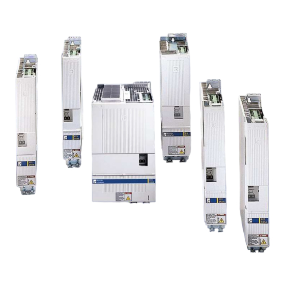
Introduction to the System Drive package ECODRIVE03 PZ5014F1.FH7 Fig. 1-1: Digital intelligent drive system The digital intelligent automation system ECODRIVE03 is the cost- e ective solution with a high level of functionality for single and multiple axis drive and control tasks. ECODRIVE03 can be used to implement a variety of drive tasks in the most varied applications. -
Page 14: An Overview Of Individual Components Of The Ecodrive03 Family
An Overview of Individual Components of the ECODRIVE03 Family mains voltage transformer line lter for power connections fuse line lter for power supply unit line contactor power supply unit drive controller auxiliary bleeder module DC 24 V rmware auxiliary capacitance module IKS - ready-made feedback cable IKG - ready-made power cable... -
Page 15: An Overview Of Drive Controllers And Auxiliary Components
An Overview of Drive Controllers and Auxiliary Components An Overview of Communications Interfaces Device type DKC11.3* DKC01.3 DKC21.3 DKC02.3 DKC22.3 DKC03.3 DKC04.3 DKC05.3 DKC06.3 Interface RS232 / RS485* Analog Interface Parallel Interface Parallel Interface 2 Stepper Interface SERCOS interface SERCOS interface 2 Pro bus-DP Interface InterBus Interface... -
Page 16: An Overview Of Measuring Systems Supported
An Overview of Measuring Systems Supported Connecting the Systems to the Encoder Inputs Type of Digital Resolver with Resolver Sine encoder EnDat Gear-type Square-wave motor servo- without FDS encoder encoder with encoder with feedback 1Vss signals 5V TTL signals Fig. 1-4: Connecting the measuring systems : single-turn or multi-turn DSF / HSF : resolver or multi-turn resolver (RSF) with... -
Page 17: Type Code For Drive Controller Dkc
Type Code for Drive Controller DKC DKC 03.3 - 040 - 7 - FW Example: Type code elds: Drive controller Series Version Type current 16 A 40 A 100 A 200 A Voltage category Firmware A rmware specifying the functions of the drive must be ordered separately. -
Page 18: Type Code Auxiliary Braking Resistor Module Bzm
Type Code Auxiliary Braking Resistor Module BZM BZM 01.3 - 01 - 07 Example: Type codes Auxiliary bleeder module Series Version Nominal power 1,0 kW Voltage category TL0202F1.FH7 Fig. 1-6: Type Code Type Code for CZM Auxiliary Braking Resistor Module CZM 01.3 - 02 - 07 Example: Type code elds... -
Page 19: Appropriate Use
The user alone carries all responsibility of the risks. Before using Rexroth Indramat products, make sure that all the pre- requisites for an appropriate use of the products are satis ed: •... -
Page 20: Areas Of Use And Application
• Rexroth Indramat has not speci cally released them for that intended purpose. Please note the speci cations outlined in the general safety instructions! customerservice@hyperdynesystems.com... -
Page 21: Introduction
If you do not have the user documentation for your equipment, contact your local Rexroth Indramat representative to send this documentation immediately to the person or persons responsible for the safe operation of this equipment. -
Page 22: Hazards By Improper Use
Safety Instructions for Electric Drives and Controls ECODRIVE03 Drive Controllers Hazards by Improper Use High voltage and high discharge current! Danger to life or severe bodily harm by electric shock! DANGER Dangerous movements! Danger to life, severe bodily harm or material damage by unintentional motor movements! DANGER High electrical voltage due to wrong... -
Page 23: General Information
ECODRIVE03 Drive Controllers Safety Instructions for Electric Drives and Controls General Information • Rexroth Indramat GmbH is not liable for damages resulting from failure to observe the warnings provided in this documentation. • Read the operating, maintenance and safety instructions in your language before starting up the machine. - Page 24 Safety Instructions for Electric Drives and Controls ECODRIVE03 Drive Controllers • Operation is only permitted if the national EMC regulations for the application are met. The instructions for installation in accordance with EMC requirements can be found in the documentation "EMC in Drive and Control Systems".
-
Page 25: Protection Against Contact With Electrical Parts
ECODRIVE03 Drive Controllers Safety Instructions for Electric Drives and Controls Protection Against Contact with Electrical Parts Note: This section refers to equipment and drive components with voltages above 50 Volts. Touching live parts with voltages of 50 Volts and more with bare hands or conductive tools or touching ungrounded housings can be dangerous and cause electric shock. -
Page 26: Protection Against Electric Shock By Protective Low Voltage (Pelv)
Protection Against Electric Shock by Protective Low Voltage (PELV) All connections and terminals with voltages between 0 and 50 Volts on Rexroth Indramat products are protective low voltages designed in accordance with international standards on electrical safety. High electrical voltage due to wrong... -
Page 27: Protection Against Dangerous Movements
ECODRIVE03 Drive Controllers Safety Instructions for Electric Drives and Controls Protection Against Dangerous Movements Dangerous movements can be caused by faulty control of the connected motors. Some common examples are: • improper or wrong wiring of cable connections • incorrect operation of the equipment components •... - Page 28 Safety Instructions for Electric Drives and Controls ECODRIVE03 Drive Controllers Dangerous movements! Danger to life, risk of injury, severe bodily harm or material damage! Ensure personal safety by means of quali ed and tested higher-level monitoring devices or measures DANGER integrated in the installation.
-
Page 29: Protection Against Magnetic And Electromagnetic Fields During Operation And Mounting
ECODRIVE03 Drive Controllers Safety Instructions for Electric Drives and Controls Disconnect electrical power to the equipment using a master switch and secure the switch against reconnection for: - maintenance and repair work - cleaning of equipment - long periods of discontinued equipment use Prevent the operation of high-frequency, remote control and radio equipment near electronics circuits and supply leads. -
Page 30: Protection Against Contact With Hot Parts
3-10 Safety Instructions for Electric Drives and Controls ECODRIVE03 Drive Controllers Protection Against Contact with Hot Parts Housing surfaces could be extremely hot! Danger of injury! Danger of burns! Do not touch housing surfaces near sources of heat! Danger of burns! CAUTION After switching the equipment o , wait at least ten (10) minutes to allow it to cool down before touching it. -
Page 31: Battery Safety
3-11 ECODRIVE03 Drive Controllers Safety Instructions for Electric Drives and Controls 3.11 Battery Safety Batteries contain reactive chemicals in a solid housing. Inappropriate handling may result in injuries or material damage. Risk of injury by incorrect handling! Do not attempt to reactivate discharged batteries by heating or other methods (danger of explosion and cauterization). - Page 32 3-12 Safety Instructions for Electric Drives and Controls ECODRIVE03 Drive Controllers Notes customerservice@hyperdynesystems.com (479) 422-0390...
-
Page 33: Technical Data
ECODRIVE03 Drive Controllers ECODRIVE03 DKC**.040, DKC**.100, DKC**.200 ECODRIVE03 DKC**.040, DKC**.100, DKC**.200 Technical Data Dimensions Drive Controller DKC**.3-040-7-FW 32.5 77.5 32.5 Fig. 4-1: Drive Controller DKC**.3-040-7-FW customerservice@hyperdynesystems.com (479) 422-0390... - Page 34 ECODRIVE03 DKC**.040, DKC**.100, DKC**.200 ECODRIVE03 Drive Controllers Drive Controller DKC**.3-100-7-FW 52.5 77.5 22.5 52.5 MB5034F1.FH7 Fig. 4-2: Drive Controller DKC**.3-100-7-FW customerservice@hyperdynesystems.com (479) 422-0390...
- Page 35 ECODRIVE03 Drive Controllers ECODRIVE03 DKC**.040, DKC**.100, DKC**.200 Drive Controller DKC**.3-200-7-FW Fig. 4-3: Drive Controller DKC**.3-200-7-FW customerservice@hyperdynesystems.com (479) 422-0390...
-
Page 36: Ambient And Operating Conditions
ECODRIVE03 DKC**.040, DKC**.100, DKC**.200 ECODRIVE03 Drive Controllers Ambient and operating conditions Note: ECODRIVE03 drive control devices and its auxiliary components are designed for control cabinet mounting. Selection lists are speci ed for each motor/drive combination. Ambient temperature and installation altitude The selection lists apply to motors and drives within the speci ed ambient and operating conditions (see "Fig. - Page 37 ECODRIVE03 Drive Controllers ECODRIVE03 DKC**.040, DKC**.100, DKC**.200 Permissible ambient and air inlet ° . . . temperature for the output ratings Max. permissible ambient and air °C The values speci ed in the selection lists for inlet temperature for reduced output output and torque are reduced in the range ratings +45...+55 °C by 2% per °C temperature increase...
-
Page 38: Electric Data Of The Individual Dkc**.3 Components
ECODRIVE03 DKC**.040, DKC**.100, DKC**.200 ECODRIVE03 Drive Controllers Electric Data of the Individual DKC**.3 Components Mains connections, Power section DKC**.3-040-7-FW and DKC**.3-100-7-FW DKC**.3-040-7-FW DKC**.3-100-7-FW three single three phase phase phase phase a t l 1 x AC 3 x AC 1 x AC 3 x AC (200 ... - Page 39 ECODRIVE03 Drive Controllers ECODRIVE03 DKC**.040, DKC**.100, DKC**.200 DKC**.3-040-7-FW DKC**.3-100-7-FW max. DC bus continuous power for a single source supply where = 3 x AC 400V, at T < 45 °C max. DC bus continuous power for a single source supply where = 3 x AC 480V, when T <...
- Page 40 ECODRIVE03 DKC**.040, DKC**.100, DKC**.200 ECODRIVE03 Drive Controllers Mains connections, Power section DKC**.3-200-7-FW DKC**.3-200-7-FW a t l 1 x AC 3 x AC (200 ... 480) ± 10% (50 ... 60 ± 2 e i f see page 11-1: "Mains Connections" Nominal charging current .
- Page 41 ECODRIVE03 Drive Controllers ECODRIVE03 DKC**.040, DKC**.100, DKC**.200 DKC**.3-200-7-FW max. DC bus continuous power for a single source supply where = 3 x AC 400V, at T < 45 °C max. DC bus continuous power for a single source supply where = 3 x AC 480V, when T <...
- Page 42 4-10 ECODRIVE03 DKC**.040, DKC**.100, DKC**.200 ECODRIVE03 Drive Controllers Block diagram of the DKC**.3-040-7-FW power section Charging current limit Softstart Line input Bleeder circuit Converter DC bus DC bus with bridge bridge connection capacitance circuit circuit with recti er output to the motor FS0218F1.FH7 Fig.
- Page 43 4-11 ECODRIVE03 Drive Controllers ECODRIVE03 DKC**.040, DKC**.100, DKC**.200 Block diagram of the DKC**.3-100-7-FW power section Charging current limit Softstart ZKS, Line input Bleeder circuit with DC bus Converter DC bus with bridge DC bus dynamic capacitance bridge connection circuit braking device circuit with recti er output to the...
- Page 44 4-12 ECODRIVE03 DKC**.040, DKC**.100, DKC**.200 ECODRIVE03 Drive Controllers Block diagram of the DKC**.3-200-7-FW power section Charging current limit Softstart ZKS, optional Line input Bleeder circuit with DC bus Converter DC bus smoothing with bridge DC bus dynamic capacitance bridge connection choke circuit braking device...
- Page 45 4-13 ECODRIVE03 Drive Controllers ECODRIVE03 DKC**.040, DKC**.100, DKC**.200 Control voltage connection for DKC (Data applies to ambient temperature of 25 °C) Designation Symbol Unit DKC**.3-040-7-FW DKC**.3-100-7-FW Control voltage . . . a t l max. allowed i t i t N3max overvoltage max.
- Page 46 4-14 ECODRIVE03 DKC**.040, DKC**.100, DKC**.200 ECODRIVE03 Drive Controllers Control voltage . . . a t l max. allowed i t i t N3max overvoltage max. charging EIN3 current max. pulse duration N3Lade of I EINmax max. input capacitance Power consumption dependent on type of unit, without external load at control outputs and (X1) encoder interface 2...
- Page 47 4-15 ECODRIVE03 Drive Controllers ECODRIVE03 DKC**.040, DKC**.100, DKC**.200 Amplitude of the DKC control voltage charging current at startup, to selecting power source I EIN3 I Nenn t N3Lade time Fig. 4-13: Example of charging current inrush of control voltage Note: For n parallel-switched inputs the charging current inrush is n-fold.
- Page 48 4-16 ECODRIVE03 DKC**.040, DKC**.100, DKC**.200 ECODRIVE03 Drive Controllers Output current characteristic curves for servo applications ( acceleration times < 400 ms) Static pro le illustrated: PEAK PEAK1 PEAK2(4kHz) PEAK2(8kHz) CONT CONT1(8kHz) CONT2(8kHz) CONT1(4kHz) CONT2(4kHz) DG0003F1.FH7 Fig. 4-16: Output current characteristic curves for servo applications See also the table with electric data page 4-6 onward.
-
Page 49: Storable Energy In The Bus
4-17 ECODRIVE03 Drive Controllers ECODRIVE03 DKC**.040, DKC**.100, DKC**.200 Storable energy in the bus Note: The higher the connection voltage the lower the energy that can be stored in the DC bus as the di erential voltage between bleeder threshold and DC bus voltage (threshold value of connecting voltage) decreases. - Page 50 4-18 ECODRIVE03 DKC**.040, DKC**.100, DKC**.200 ECODRIVE03 Drive Controllers DKC**.3-200-7-FW Line input voltage U in V Fig. 4-19: Storable energy in the bus DKC**.3-200-7-FW customerservice@hyperdynesystems.com (479) 422-0390...
-
Page 51: Mains Supply Options
4-19 ECODRIVE03 Drive Controllers ECODRIVE03 DKC**.040, DKC**.100, DKC**.200 Mains supply options Single source supply "Single source supply" is the standard mains supply if only one DKC driver controller (or a DKC drive controller with additional components) is to be supplied with mains voltage. Characteristic for the single source supply is that the mains voltage is applied to the DKC drive controller via individual mains connections. -
Page 52: Number Of Ecodrive03 Units And Auxiliary Components On One Dc Bus
4-20 ECODRIVE03 DKC**.040, DKC**.100, DKC**.200 ECODRIVE03 Drive Controllers Number of ECODRIVE03 Units and Auxiliary Components on one DC Note: The total number of units with bleeder set up on one DC bus should not exceed max. 12 . Up to this number combinations as shown below are possible. -
Page 53: Selection Criteria For Supply Options
4-21 ECODRIVE03 Drive Controllers ECODRIVE03 DKC**.040, DKC**.100, DKC**.200 Selection criteria for supply options Mains supply options Selection criteria for Single Group supply Group supply Central supply "Mains supply source without DC bus with DC bus options." supply connection connection only 40 A units only 100 A units only 200 A units Units with di erent current... - Page 54 4-22 ECODRIVE03 DKC**.040, DKC**.100, DKC**.200 ECODRIVE03 Drive Controllers Arranging the Single source supply Note: DC bus connection of drive controllers that are connected to the mains via separate contactors is not allowed! DKC**.3 DKC**.3 CZM1.3 BZM1.3 -016 -040 -100 -200 Ap5109f1.fh7 Fig.
- Page 55 4-23 ECODRIVE03 Drive Controllers ECODRIVE03 DKC**.040, DKC**.100, DKC**.200 Arranging the Group supply without DC bus connection DKC**.3 DKC**.3 DKC**.3 CZM1.3 BZM1.3 -016 -016 -040 -100 -040 -040 -200 -100 -100 -200 -200 Ap5115f1.fh7 Fig. 4-23: Group supply without DC bus connection Note: In addition to the illustrated connections of the BZM01.3 at the DC bus, the following connections must be wired as well:...
- Page 56 4-24 ECODRIVE03 DKC**.040, DKC**.100, DKC**.200 ECODRIVE03 Drive Controllers Arranging the Group supply with DC bus connection Note: Increase the available continuous power in the common DC bus for the devices DKC**.3-040. See also page 16-5 Calculating the allowed continuous braking resistor and DC bus power. DKC**.3 DKC**.3 -040...
- Page 57 4-25 ECODRIVE03 Drive Controllers ECODRIVE03 DKC**.040, DKC**.100, DKC**.200 Arranging the Central supply Note: DKC**.3-040 as supply unit in "Central supply" not allowed! Note: The connection of the devices DKC**.3-100 and DKC**.3-200 to the mains power is not to increase the allowed DC bus continuous power but to protect the integrated DC bus dynamic brake setup (ZKS).
-
Page 58: Energy Circuit Dkc**.3 Using "Central Supply" As An Example
4-26 ECODRIVE03 DKC**.040, DKC**.100, DKC**.200 ECODRIVE03 Drive Controllers Energy circuit DKC**.3 using "Central supply" as an example Load Load 1/F P FS0211f1.fh7 Fig. 4-26: Energy circuit DKC**.3 using "Central supply" as an example customerservice@hyperdynesystems.com (479) 422-0390... -
Page 59: Allowed Dc Bus Peak Power
4-27 ECODRIVE03 Drive Controllers ECODRIVE03 DKC**.040, DKC**.100, DKC**.200 Allowed DC bus Peak Power Note: Diagrams apply to single and central supply! DKC**.3-040-7-FW Relationship peak to DC bus continuous power t in s Fig. 4-27: Allowed peak power in DC bus of DKC**.3-040-7-FW DKC**.3-040-7-FWs are not suited for drive applications if the required intermittent operating power of the unit ’s nominal power exceeds 50%! DKC**.3-100-7-FW... -
Page 60: Allowed Dc Bus Continuous Power Without Auxiliary Components
4-28 ECODRIVE03 DKC**.040, DKC**.100, DKC**.200 ECODRIVE03 Drive Controllers Allowed DC bus continuous power without auxiliary components DKC**.3-040-7 in "Single source supply": Line input voltage U 3*AC in V Fig. 4-30: Allowed DC bus continuous power for Single source supply DKC**.3-040-7 DKC**.3-040-7 in "Group supply without DC bus connection": No increase in the allowed continuous power rating! - Page 61 4-29 ECODRIVE03 Drive Controllers ECODRIVE03 DKC**.040, DKC**.100, DKC**.200 DKC**.3-100-7 in "Single source supply": Line input voltage U 3*AC in V Fig. 4-31: Allowed DC bus continuous power for Single source supply DKC**.3-100-7 DKC**.3-100-7 in "Group supply without DC bus connection": No increase in the allowed continuous power! See page 4-23: "Arranging the Group supply without DC bus connection"...
- Page 62 4-30 ECODRIVE03 DKC**.040, DKC**.100, DKC**.200 ECODRIVE03 Drive Controllers DKC**.3-200-7 in "Single source supply": Line input voltage U 3*AC in V Fig. 4-32: Allowed DC bus continuous power for Single source supply DKC**.3-200-7 DKC**.3-200-7 in "Group supply without DC bus connection": No increase in the allowed continuous power! See page 4-23: "Arranging the Group supply without DC bus connection"...
-
Page 63: Allowed Dc Bus Continuous Power With Czm01.3 Auxiliary Components
4-31 ECODRIVE03 Drive Controllers ECODRIVE03 DKC**.040, DKC**.100, DKC**.200 Allowed DC bus continuous power with CZM01.3 auxiliary components Note: The allowed DC bus continuous power of the drive controllers is increased by adding components. • CZM01.3 reduces the load of the DC bus capacitor in drive controllers. DKC**.3-040-7 with CZM01.3 in "Single source supply": No increase in the allowed continuous power! DKC**.3-040-7 with CZM01.3 in "Group supply without... - Page 64 4-32 ECODRIVE03 DKC**.040, DKC**.100, DKC**.200 ECODRIVE03 Drive Controllers DKC**.3-100-7 with CZM01.3 in "Single source supply": 14,00 12,00 10,00 8,00 6,00 4,00 2,00 0,00 Line input voltage U 3*AC in V Fig. 4-33: Allowed DC bus continuous power for Single source supply DKC**.3-100-7 with CZM01.3 DKC**.3-100-7 with CZM01.3 in "Group supply without DC bus connection":...
- Page 65 4-33 ECODRIVE03 Drive Controllers ECODRIVE03 DKC**.040, DKC**.100, DKC**.200 DKC**.3-200-7 with CZM01.3 in "Single source supply": Line input voltageU 3*AC in V Fig. 4-34: Allowed DC bus continuous power for Single source supply DKC**.3-200-7 with CZM01.3 DKC**.3-200-7 with CZM01.3 in "Group supply without DC bus connection": No increase in the allowed continuous power! See page 4-23: "Arranging the Group supply without DC bus connection"...
-
Page 66: Allowed Dc Bus Continuous Power With Czm01.3 And Gld12 Smoothing Choke
4-34 ECODRIVE03 DKC**.040, DKC**.100, DKC**.200 ECODRIVE03 Drive Controllers Allowed DC bus continuous power with CZM01.3 and GLD12 smoothing choke Note: The allowed DC bus continuous power of a DKC is increased by adding components. • CZM01.3 reduces the load on the DC bus capacitor in DKCs. - Page 67 4-35 ECODRIVE03 Drive Controllers ECODRIVE03 DKC**.040, DKC**.100, DKC**.200 DKC**.3-200-7 with CZM01.3 and lter choke GLD12 in "Single source supply": Line input voltage U 3*AC in V Fig. 4-35: Allowed DC bus continuous power for single source supply DKC**.3-200-7 with CZM01.3 and lter choke GLD12 DKC**.3-200-7 with CZM01.3 and lter choke GLD12 in "Group supply without DC bus connection": No increase in the allowed continuous power!
-
Page 68: Allowed Dc Bus Continuous Power With Single-Phase Mains Connection
4-36 ECODRIVE03 DKC**.040, DKC**.100, DKC**.200 ECODRIVE03 Drive Controllers Allowed DC bus continuous power with single-phase mains connection The operation of a single-phase mains supply reduces the allowed DC bus continuous power as per the following diagram. Note: The single-phase mains connection is only permitted with single source supply! With single-phase operation peak power in the DC bus is the same as continuous power. - Page 69 4-37 ECODRIVE03 Drive Controllers ECODRIVE03 DKC**.040, DKC**.100, DKC**.200 DKC**.3-200-7 1000 2000 3000 4000 5000 6000 7000 8000 9000 10000 —————: DKC**.3-200-7, 50 Hz without CZM — — — —: DKC**.3-200-7, 50 Hz with CZM Fig. 4-37: Allowed DC bus continuous power in single-phase mode with 50 Hz Allowed DC bus continuous power in single-phase mode with networks with a frequency of 60 Hz DKC**.3-040-7, DKC**.3-100-7...
- Page 70 4-38 ECODRIVE03 DKC**.040, DKC**.100, DKC**.200 ECODRIVE03 Drive Controllers DKC**.3-200-7 2000 4000 6000 8000 10000 12000 —————: DKC**.3-200-7, 60 Hz without CZM — — — —: DKC**.3-200-7, 60 Hz with CZM Fig. 4-39: DC bus continuous power in single-phase mode with 60 Hz Note: Do not operate DKC**.3-200-7s with single-phase mains with smoothing choke !
-
Page 71: Ce Label, C-Ul Listing, Tests
4-39 ECODRIVE03 Drive Controllers ECODRIVE03 DKC**.040, DKC**.100, DKC**.200 CE label, C-UL listing, Tests CE label: CEf1.fh7 Fig. 4-40: CE label C-UL listing: • Per UL508 C under le no. E134201. LISTED INDUSTRIAL CONTROL EQUIPMENT 97Y4 ULf2.fh7 Fig. 4-41: C-UL listing DKC**.3-040-7s and DKC**.3-100-7s are C-UL listed. -
Page 72: Electrical Connections - Independent Of The Drive Controller Type
4-40 ECODRIVE03 DKC**.040, DKC**.100, DKC**.200 ECODRIVE03 Drive Controllers Electrical connections - independent of the drive controller type A look at the drive controller and connector designations Front view encoder 1 encoder 2 XS2: cable clamp shield connections digital and analog in-/ outputs control voltage supply and control signals... - Page 73 4-41 ECODRIVE03 Drive Controllers ECODRIVE03 DKC**.040, DKC**.100, DKC**.200 encoder 1 encoder 2 XS2: cable clamp shield connections digital and analog in-/ outputs control voltage supply and control signals RS232/ RS485 device-typical interface programming module ( rmware, parameter) H1 - diagnosis indicator S1 - fault clearance button S2, S3 - adress switch motor temperature monitoring...
- Page 74 4-42 ECODRIVE03 DKC**.040, DKC**.100, DKC**.200 ECODRIVE03 Drive Controllers Connections on top of the drive controller DKC**.3-040-7-FW X11: X10: XS3: expansion interface for incremental encoder/ cable clamp interface SSI-emulation ZKS control bracket shield connection DKC**.3-100-7-FW Fa5025f1.fh7 Fig. 4-45: Connections on top of unit for DKC**.3-040-7-FW and DKC**.3-100-7-FW customerservice@hyperdynesystems.com (479) 422-0390...
- Page 75 4-43 ECODRIVE03 Drive Controllers ECODRIVE03 DKC**.040, DKC**.100, DKC**.200 DKC**.3-200-7-FW XS3: X11: X10: cable clamp bracket expansion incremental encoder/ interface for Shield connection interface ZKS control SSI-emulation Fa5089f1.fh7 Fig. 4-46: Connections on top of unit for DKC**.3-200-7-FW customerservice@hyperdynesystems.com (479) 422-0390...
-
Page 76: Independent Of The Drive Controller Type - Total Connecting Diagram
4-44 ECODRIVE03 DKC**.040, DKC**.100, DKC**.200 ECODRIVE03 Drive Controllers Independent of the drive controller type – total connecting diagram XS*: shield connection XE*: protective conductor connection X* : clamp pin connection for n.c. +24V designation control voltage (S3) G1Sin+ (S4) G1Cos+ drive halt spring tension drive enable... -
Page 77: X1, Connections For Control Voltage
4-45 ECODRIVE03 Drive Controllers ECODRIVE03 DKC**.040, DKC**.100, DKC**.200 X1, Connections for Control voltage Technical description of connector Illustration: Ap5264f1.FH7 Fig. 4-48: Connector X1 Design: Type No. of pins Design Spring contact 2 x 4 Bushing on connector Fig. 4-49: Design Connection cross section: Cross section Cross section... - Page 78 4-46 ECODRIVE03 DKC**.040, DKC**.100, DKC**.200 ECODRIVE03 Drive Controllers Note: Strong mechanical in uence on the test tap of the terminals can increase the transition resistance and destroy the terminals. Note: The input 0 V is connected directly to the device potential. The utilization of an insulation monitoring for +24 V and 0 V against device is therefore not possible! .
- Page 79 4-47 ECODRIVE03 Drive Controllers ECODRIVE03 DKC**.040, DKC**.100, DKC**.200 Drive halt (AH) and Drive enable (RF) Note: • Inputs work with inactive bus communication. • Inputs don ’t work with active bus communication (SERCOS interface, Pro bus-DP, ...). Connection device-external device-internal AH and RF: drive halt drive enable...
- Page 80 4-48 ECODRIVE03 DKC**.040, DKC**.100, DKC**.200 ECODRIVE03 Drive Controllers Ready to operate contact Bb Connection device-external device-internal ready for operation AP5122F1.FH7 Fig. 4-56: Connections for ready to operate contact Loadability of the connection c t i a t l c t i : t n : t n i n i...
-
Page 81: X2, Serial Interface
4-49 ECODRIVE03 Drive Controllers ECODRIVE03 DKC**.040, DKC**.100, DKC**.200 X2, Serial Interface Note: Serial interfaces are generally used for programming, parameterization and diagnoses upon commissioning and during service. It can be operated either as RS232 or RS485. Technical description of connector Illustration: Ap5265f1.FH7 Fig. - Page 82 4-50 ECODRIVE03 DKC**.040, DKC**.100, DKC**.200 ECODRIVE03 Drive Controllers RS232 interface The RS232 interface is used for programming, parameterization and diagnoses at start up and service. It makes possible: • a participant number of maximum 1 • a transmission length of up to 15 m •...
- Page 83 4-51 ECODRIVE03 Drive Controllers ECODRIVE03 DKC**.040, DKC**.100, DKC**.200 RS485 interface The RS485 interface is used for programming, parameterization and diagnoses at start up and service. It makes possible: • the implementation of a serial bus with up to 31 participants connected via a two-wire cable (half duplex mode) •...
- Page 84 4-52 ECODRIVE03 DKC**.040, DKC**.100, DKC**.200 ECODRIVE03 Drive Controllers Connection for RS485 interface: 1. DKC 2. DKC INS0619 INS0619 RS485+ RS485+ RS485- RS485- to further devices RS232/RS485 converter INK0572 or PC plug- in card RS 485 Ap5316f1.fh7 Connect outer screen to device potential on PC side and converter side (strain relief of metallic connector case) Connect the metallic connector case with the device potential using the fastening screws of the connector...
-
Page 85: X3, Digital And Analog I/Os
4-53 ECODRIVE03 Drive Controllers ECODRIVE03 DKC**.040, DKC**.100, DKC**.200 X3, Digital and analog I/Os Technical description of connector Illustration: Ap5263f1.FH7 Fig. 4-63: Connector X3 Design: Type No. of pins Design Spring contact 2 x 9 Bushing on connector Fig. 4-64: Design Connection cross section: Cross section Cross section... - Page 86 4-54 ECODRIVE03 DKC**.040, DKC**.100, DKC**.200 ECODRIVE03 Drive Controllers Input circuit Digital inputs: Ap5183f1.fh7 Schematics no data Fig. 4-67: Input circuit Inputs Input voltage: min. max. Digital inputs: High 16 V 30 V -0,5 V ± r i f Fig. 4-68: Inputs Note: If the inputs are controlled by a power supply other than the...
- Page 87 4-55 ECODRIVE03 Drive Controllers ECODRIVE03 DKC**.040, DKC**.100, DKC**.200 Digital outputs (ready, warning and U -message) Connection Digital outputs: Ready message Ready Warning message warning -message AP5277F1.FH7 Fig. 4-69: Control outputs Output circuit connection Digital outputs: Ap5184f1.fh7 Schematics no data Fig. 4-70: Output circuit Output connections Output voltage:...
- Page 88 4-56 ECODRIVE03 DKC**.040, DKC**.100, DKC**.200 ECODRIVE03 Drive Controllers Depending on operating mode and parameter programming a number of Warnings: monitoring functions are conducted. If a condition is detected that still allows for correct operations but would eventually lead to an error, then the warning is set to high.
- Page 89 4-57 ECODRIVE03 Drive Controllers ECODRIVE03 DKC**.040, DKC**.100, DKC**.200 Analog inputs 1 and 2 Connection Analog inputs: analog E1+ analog E1- analog inputs analog E2+ analog E2- AP5314F1.FH7 Fig. 4-76: Analog inputs Input circuit Analog inputs: AP5296F1.FH7 Schematics no data no data Fig.
- Page 90 4-58 ECODRIVE03 DKC**.040, DKC**.100, DKC**.200 ECODRIVE03 Drive Controllers The analog di erential inputs 1 and 2 can be parametrized as needed and Analog inputs: can be used, for example, as an analog speed command value inputs, override inputs or for analog torque reduction. See Function Description also: "Analog inputs".
-
Page 91: X4, Encoder 1
4-59 ECODRIVE03 Drive Controllers ECODRIVE03 DKC**.040, DKC**.100, DKC**.200 X4, Encoder 1 Technical description of connector Illustration: Ap5265f1.FH7 Fig. 4-81: Connector X4 Design: Type No. of pins Design D-SUB bushing on unit Fig. 4-82: Design Connection cross section: Cross section Cross section Cross section single wire multi core wire... - Page 92 4-60 ECODRIVE03 DKC**.040, DKC**.100, DKC**.200 ECODRIVE03 Drive Controllers Input circuit G1Sin+ (S3), G1Sin- (S1): G1Sin+ (S3), G1Sin- (S1): AP5296F1.FH7 Schematics no data no data Fig. 4-85: Input circuit Features of the di erential input circuit G1Sin+ (S3), G1Sin- (S1): Digital servo Resolver feedback max.
- Page 93 4-61 ECODRIVE03 Drive Controllers ECODRIVE03 DKC**.040, DKC**.100, DKC**.200 Signal allocation to the actual position value Signal allocation signal designation signal form actual position value (X4) (with default setting) G1Sin+(S3) G1Sin- (S1) (sine 1 Vss without increasing 120 Ohm matching resistor, I²C-Bus) G1Cos+(S4) G1Cos- (S2)
-
Page 94: X5, Dc Bus, Motor And Mains Connections
4-62 ECODRIVE03 DKC**.040, DKC**.100, DKC**.200 ECODRIVE03 Drive Controllers X5, DC bus, Motor and Mains Connections Technical description of connector Illustration: Ap5267f1.FH7 Fig. 4-89: Connector X5 Design: Type No. of pins Design connection block 2 / 3 / 3 screw-in connection for ring terminals M5 Fig. - Page 95 4-63 ECODRIVE03 Drive Controllers ECODRIVE03 DKC**.040, DKC**.100, DKC**.200 Damage possible if DC bus connections L+ and L- are reversed! Make sure polarity is correct. CAUTION If the DC bus rails supplied do not make a connection possible, then use wire short twisted wires to do so.
- Page 96 Motor: motor connection AP5302F1.FH7 Fig. 4-94: Motor connections Use Rexroth Indramat motor power cables to connect motor and Cable controller. Motor: Note: For technical data on connections and cross sections, see the motor project planning manual. Cable length: Maximum length equals 75 m: •...
- Page 97 4-65 ECODRIVE03 Drive Controllers ECODRIVE03 DKC**.040, DKC**.100, DKC**.200 No guarantee! If third party cables are used, then the guarantee is forfeited for the entire system. Use Rexroth Indramat cables! WARNING customerservice@hyperdynesystems.com (479) 422-0390...
- Page 98 4-66 ECODRIVE03 DKC**.040, DKC**.100, DKC**.200 ECODRIVE03 Drive Controllers Mains connections The mains connector serves as the connection of the drive controller with the power supply. Single-phase mains connection: device-external device-internal n.c. AP5370F1.FH7 Fig. 4-96: Single-phase mains connection Three-phase mains connection: device-external device-internal mains connection...
-
Page 99: X6, Motor Temperature Monitoring And Holding Brakes
4-67 ECODRIVE03 Drive Controllers ECODRIVE03 DKC**.040, DKC**.100, DKC**.200 X6, Motor temperature monitoring and holding brakes Technical description of connector Illustration: Ap5264f1.FH7 Fig. 4-98: Connector X6 Design: Type No. of pins Design Spring contact 2 x 4 Bushing on connector Fig. 4-99: Design Connection cross section: Cross section... - Page 100 Motor temperature monitoring (TM+, TM) Connections TM+ and TM- are used to evaluate the temperature of connected Rexroth Indramat motors. These are equipped with a temperature-dependent resistor (either PTC or NTC dependent on the motor type) to monitor temperature. The connection leads are in the motor power cable.
- Page 101 4-69 ECODRIVE03 Drive Controllers ECODRIVE03 DKC**.040, DKC**.100, DKC**.200 Holding brake (BR+, BR-) Dangerous movements! Danger to personnel from falling or dropping axes! The standard equipment motor brake or an external brake controlled directly by the servo drive are not DANGER su cient to guarantee the safety of personnel! Personnel safety must be acquired with higher- ranking procedures:...
- Page 102 4-70 ECODRIVE03 DKC**.040, DKC**.100, DKC**.200 ECODRIVE03 Drive Controllers Voltage connection for brakes Note: The motor holding brake is not supplied by the controller. Given one voltage source for brake and control voltage, use parallel leads from the voltage source. Note the voltage range for the motor holding brake according to the motor projection.
- Page 103 4-71 ECODRIVE03 Drive Controllers ECODRIVE03 DKC**.040, DKC**.100, DKC**.200 Voltage connection for brakes a t l : 8 / on DKC: current consumption at X6.5 and needed supply see "Technical data" voltage: brake in the motor manual max. allowed current load when looping through DC 10 A brake supply over X6.5/6 to X6.7/8: wire cross section:...
- Page 104 4-72 ECODRIVE03 DKC**.040, DKC**.100, DKC**.200 ECODRIVE03 Drive Controllers Basic connection of motor power, holding brake and motor temperature monitoring A1 A2 A3 AC-Motor Holding Temperature brake dependent resistance AP5107F1.FH7 Fig. 4-106: Connection of motor cable, holding brake and temperature monitor for motors with connectors A1 A2 A3 AC-Motor...
-
Page 105: X7, Connection For Programming Module
4-73 ECODRIVE03 Drive Controllers ECODRIVE03 DKC**.040, DKC**.100, DKC**.200 X7, Connection for Programming module Programming module The programming module can be broken down into • Parameter module for user-speci c parameters • Firmware modules for unit-speci c rmware Programming module Firmware module Parameter module Ap5146f1.fh7 Fig. - Page 106 4-74 ECODRIVE03 DKC**.040, DKC**.100, DKC**.200 ECODRIVE03 Drive Controllers Setting the Drive Address Two decade switches are used to set the drive address. It can be set to Switch S2, S3; any number between 1 and 99. drive address: Example: Switch setting S3 = 9 (value of tens) Switch setting S2 = 1 (value of ones) Drive address = 9 * 10 + 1 = 91 Switch S2...
-
Page 107: X8, Encoder 2
4-75 ECODRIVE03 Drive Controllers ECODRIVE03 DKC**.040, DKC**.100, DKC**.200 X8, Encoder 2 Technical description of connector Illustration: Ap5266f1.FH7 Fig. 4-110: Connector X5 Design: Type No. of pins Design D-SUB Pins on unit Fig. 4-111: Design Connection cross section: Cross section Cross section Cross section single wire multi core wire... - Page 108 4-76 ECODRIVE03 DKC**.040, DKC**.100, DKC**.200 ECODRIVE03 Drive Controllers Input circuit for sine signals G2Sin+ (A+), G2Sin- (A-): G2Sin+ (A+), G2Sin- (A-): AP5299F1.FH7 Schematics no data no data no data no data 120R no data no data Fig. 4-114: Input circuit for sine signals Input circuit for square-wave signals G2Sin+ (A+), G2Sin- (A-): AP5300F1.FH7 Schematics...
- Page 109 4-77 ECODRIVE03 Drive Controllers ECODRIVE03 DKC**.040, DKC**.100, DKC**.200 Square-wave encoder Input voltage Signal amplitude nominal: min. max. (referencing unit ground) High > 2.4 V < 0,8 V Fig. 4-117: Features of the di erential input (Square-wave encoder) See "G2Sin+ (A+), G2Sin- (A-):" G2Ref+ (R+), G2Ref- (R-): See "G2Sin+ (A+), G2Sin- (A-):"...
- Page 110 4-78 ECODRIVE03 DKC**.040, DKC**.100, DKC**.200 ECODRIVE03 Drive Controllers Signal allocation to the actual position value Signal allocation signal designation signal form actual position value (X8) (with default setting) G2Sin+(A+) G2Sin- (A-) sine (1Vss) G2Cos+(B+) without absolute value reducing G2Cos- (B-) (e.g.
- Page 111 4-79 ECODRIVE03 Drive Controllers ECODRIVE03 DKC**.040, DKC**.100, DKC**.200 Allowed encoder cable lengths Selecting wire cross sections Note: The current consumption of the connected encoder systems generates a voltage drop due to the resistively ( dependent upon the wire cross sections and lengths) of the wire. This reduces the signal at the encoder input.
- Page 112 4-80 ECODRIVE03 DKC**.040, DKC**.100, DKC**.200 ECODRIVE03 Drive Controllers 2. Without sensor connection in the encoder lead 0,05 0,15 0,25 I [A] A = 0,25 mm ² A = 0,5 mm ² A = 1,0 mm ² cable length current wire cross sections Fig.
-
Page 113: X9, Incremental And Absolute Encoder Emulation (Ssi Format)
4-81 ECODRIVE03 Drive Controllers ECODRIVE03 DKC**.040, DKC**.100, DKC**.200 X9, Incremental and Absolute Encoder Emulation (SSI format) Technical description of connector Illustration: Ap5269f1.FH7 Fig. 4-122: Connector X9 Design: Type No. of pins Design Spring contact 2 x 6 Bushing on connector Fig. - Page 114 4-82 ECODRIVE03 DKC**.040, DKC**.100, DKC**.200 ECODRIVE03 Drive Controllers Incremental encoder emulation Connection length l Incremental encoder emulation: IgsUA1+ IgsUA1- positioning IgsUA2+ interface IgsUA2- -incremental- IgsUA0+ IgsUA0- 0 V ext AP5282F1.FH7 Fig. 4-125: Connection of incremental actual position value output Di erential outputs incremental Output voltage: min.
- Page 115 4-83 ECODRIVE03 Drive Controllers ECODRIVE03 DKC**.040, DKC**.100, DKC**.200 Output frequency f: Line Quantity • Revolution output frequency velocity (rotary) Fig. 4-128: Calculating the output frequency f Note: The output frequency results from the parameter setting. => See also rmware functional description: "Encoder Emulation".
- Page 116 4-84 ECODRIVE03 DKC**.040, DKC**.100, DKC**.200 ECODRIVE03 Drive Controllers Absolute Encoder Emulation (SSI format) Connection length l Absolute Encoder Emulation: SSIData+ positioning- SSIData- interface -absolute- SSIClk+ SSIClk- 0 V ext AP5283F1.FH7 Fig. 4-129: Output of absolute actual position value in SSI format Di erential input circuit SSICLK+ absolute encoder emulation:...
- Page 117 4-85 ECODRIVE03 Drive Controllers ECODRIVE03 DKC**.040, DKC**.100, DKC**.200 Pulse diagram for absolute actual position output (SSI format) resolution for 4096 rotations resolution for 1 rotations pulse 9 10 11 12 13 14 15 16 17 18 19 20 21 22 23 24 data G23 G22 G21 G20 G19 G18 G17 G16 G15 G14 G13 G12 G11 G10 G9 G8 G7 G6 G5 G4 G3 G2 G1 G0 G23 G22...
-
Page 118: X10, Ecox Expansion Interface
4-86 ECODRIVE03 DKC**.040, DKC**.100, DKC**.200 ECODRIVE03 Drive Controllers X10, EcoX Expansion interface Note: EcoX allows: • synchronizing drives and I/O modules • connecting up to 2 modules with 16 digital inputs and outputs each per drive controller • transmitting a command value from one drive controller to a maximum of three other drive controllers Technical description of connector Illustration:... - Page 119 4-87 ECODRIVE03 Drive Controllers ECODRIVE03 DKC**.040, DKC**.100, DKC**.200 EcoX-Bus: drive or drive or drive E/A- E/A- module module IAN+ 120 R EcoX bus 120 R IAN- voltage IAN+ 3,5V 2,5V IAN- 1,5V dominant recessive recessive time SV5179F1.FH7 Fig. 4-137: EcoX interface Bus cable: bus terminating resistors on both ends of the 2 x 120 R / 250 mW...
-
Page 120: X11, Dc Bus Dynamic Brake (Zks), U Power Supply
4-88 ECODRIVE03 DKC**.040, DKC**.100, DKC**.200 ECODRIVE03 Drive Controllers X11, DC bus dynamic brake (ZKS), U power supply Technical description of connector Illustration: Ap5263f1.FH7 Fig. 4-138: Connector X11 Design: Type No. of pins Design Spring contact 2 x 9 Bushing on connector Fig. - Page 121 4-89 ECODRIVE03 Drive Controllers ECODRIVE03 DKC**.040, DKC**.100, DKC**.200 ZKS control supply Note: Internal DC bus dynamic brake setup (ZKS) not in DKC**.3-040-7-FW. Connection device-external device-internal +24Vpro and 0V: +24Vpro ZKS1 ZKS2 AP5284F1.FH7 Fig. 4-141: DC bus dynamic brake control At delivery: with bridges at: X11.1 X11.2 X11.10 to...
- Page 122 4-90 ECODRIVE03 DKC**.040, DKC**.100, DKC**.200 ECODRIVE03 Drive Controllers ZKS control input See page 4-89: "ZKS control supply". Connection ZKS1 and ZKS2: Input circuit ZKS1 and ZKS2: ZKS1 ZKS2 AP5280F1.FH7 Schematics 0.7V 0.1µF 0.1µF Fig. 4-143: Input circuit Inputs Input voltage: min.
- Page 123 4-91 ECODRIVE03 Drive Controllers ECODRIVE03 DKC**.040, DKC**.100, DKC**.200 Protecting the ZKS setup with mains voltage applied: Note: If mains voltage applied at X5 then DC bus dynamic brake not executed! The ZKS control is realized with the currentless input. ZKS input: with current: "H"...
- Page 124 4-92 ECODRIVE03 DKC**.040, DKC**.100, DKC**.200 ECODRIVE03 Drive Controllers See page 4-47: "Drive halt (AH) and Drive enable (RF)". Inputs power supply: With central mains supply (see page 4-25: "Arranging the Central supply") power supply: the DKC ’s operated on one DC bus must be informed about the status of the power supply.
-
Page 125: X12, Optional Choke Connection For Dkc**.3-200-7
4-93 ECODRIVE03 Drive Controllers ECODRIVE03 DKC**.040, DKC**.100, DKC**.200 X12, Optional Choke Connection for DKC**.3-200-7 Technical description of connector Illustration: Ap5294f1.FH7 Fig. 4-150: Connector X12 Design: Type No. of pins Design Screw-in connector screw-in connection for ring terminals M5 Fig. 4-151: Design Tightening torque: min. - Page 126 4-94 ECODRIVE03 DKC**.040, DKC**.100, DKC**.200 ECODRIVE03 Drive Controllers wire length: Wire max. 10 m DR+, DR-: wire cross section: min. 10 mm ², but not smaller than mains wire cross section wire routing twisted voltage resistance of single litz to ground: >...
-
Page 127: Xe1, Xe2 Protective Conductor Connections For Motor And Mains
4-95 ECODRIVE03 Drive Controllers ECODRIVE03 DKC**.040, DKC**.100, DKC**.200 XE1, XE2 Protective conductor connections for motor and mains Technical description of connector See page 4-40: "A look at the drive controller and connector Illustration: designations". Design: Type No. of pins Design screw-in connection screw-in connection for ring terminals M5... -
Page 128: Xs1, Xs2, Xs3 Shield Connections
4-96 ECODRIVE03 DKC**.040, DKC**.100, DKC**.200 ECODRIVE03 Drive Controllers XS1, XS2, XS3 Shield Connections Connection for shield: • Total motor cable shield • Holding brake • Motor temperature monitoring • Mains supply Connection for shields of cables at X1, X3 and those for the command communication interfaces. -
Page 129: Dkc 01.3-***-7-Fw - Parallel Interface
4-97 ECODRIVE03 Drive Controllers ECODRIVE03 DKC**.040, DKC**.100, DKC**.200 Electrical Connections – dependent on the drive controller type DKC 01.3-***-7-FW – Parallel Interface View of interface to command communications X15: Parallel Interface (female, 25 pins) FA5032F1.FH7 Fig. 4-159: View of interface to command communications Technical description of connector Design: Type... - Page 130 4-98 ECODRIVE03 DKC**.040, DKC**.100, DKC**.200 ECODRIVE03 Drive Controllers Connection diagram for Parallel Interface Note: If a power supply other than the DC24 volts of the DKC controls the inputs, then connect the standard lead (GND) of the separate mains section to X15.13 (0 V). Connection Parallel interface Parallel Interface:...
- Page 131 4-99 ECODRIVE03 Drive Controllers ECODRIVE03 DKC**.040, DKC**.100, DKC**.200 Default allocation of the binary Inputs Outputs I/Os: Pos 0 PosQ 0 Pos 1 PosQ 1 Pos 2 PosQ 2 Pos 3 PosQ 3 Pos 4 PosQ 4 Pos 5 PosQ 5 Start End position reached Start home...
- Page 132 4-100 ECODRIVE03 DKC**.040, DKC**.100, DKC**.200 ECODRIVE03 Drive Controllers Output circuit Q 0 – Q 9: Ap5184f1.fh7 Schematics no data Fig. 4-167: Output circuit Signal level of outputs Output voltage: min. max. Q 0 – Q 9: High 16 V (an X1.1-1V) – 1.5 V -0.5 V Output current I 80 mA...
- Page 133 4-101 ECODRIVE03 Drive Controllers ECODRIVE03 DKC**.040, DKC**.100, DKC**.200 Signal voltages of di erential Input voltages min. max. inputs: Di erence: |3| V |5| V : t n . n i max. |5| mA |15| mA Fig. 4-171: Di erential inputs Overloads destroy inputs! Maximum input current may not be exceeded.
- Page 134 4-102 ECODRIVE03 DKC**.040, DKC**.100, DKC**.200 ECODRIVE03 Drive Controllers Control inputs for stepper motor mode (SM1+, SM1-, SM2+, SM2-) Note: The control of the stepper motor interface with di erential signals is preferable to single-channel control because the noise immunity of di erential signals is better than zero- referenced signals.
- Page 135 4-103 ECODRIVE03 Drive Controllers ECODRIVE03 DKC**.040, DKC**.100, DKC**.200 Controlling with the stepper 1: Quadrature-signals motor interface: SM 1 SM 2 turning ccw turning cw t1 1,4 µs 2: Seperate signals for forward/ backward count SM 1 SM 2 turning ccw turning cw t2 5,6 µs 3: Count and direction signals...
-
Page 136: Dkc 02.3-***-7-Fw - Sercos Interface
4-104 ECODRIVE03 DKC**.040, DKC**.100, DKC**.200 ECODRIVE03 Drive Controllers DKC 02.3-***-7-FW – SERCOS interface View of command communication interface ber optic connection for SERCOS ring distortion LED of SERCOS interface ERROR switch to set transmitting power switch to set data rate FA5031F1.FH7 Fig. - Page 137 4-105 ECODRIVE03 Drive Controllers ECODRIVE03 DKC**.040, DKC**.100, DKC**.200 Switch S20 The transmitter power and the data rate for the SERCOS interface are set Data rate, transmitter power with the switch S20. The DKC is factory set to an average transmitter power (-4.5 dBm) and the lowest data rate(2 Mbit/s).
- Page 138 (*1): The data for the maximum lengths of the ber optic cable only apply if the following preconditions have been met: • Rexroth Indramat ber optic cables IKO 982, IKO985 or IKO 001 are used • Connection without separation. If couplings are used, the maximum length for plastic ber optic cables is reduced by about 10 meter, 100 meters for glass ber optic cables.
- Page 139 4-107 ECODRIVE03 Drive Controllers ECODRIVE03 DKC**.040, DKC**.100, DKC**.200 Selecting ber optic IKO0985 / . . . connections: for external control cabinet installation) SERCOS interface length in meters ø 2mm ERROR ERROR ERROR ERROR IKO0982/ . . . dependent on how the devices IKO0982 / are arranged length in meters...
-
Page 140: Dkc 03.3-***-7-Fw - Pro Bus-Dp Interface
4-108 ECODRIVE03 DKC**.040, DKC**.100, DKC**.200 ECODRIVE03 Drive Controllers DKC 03.3-***-7-FW – Pro bus-DP Interface View of command communication interface Pro bus interface (female, 9 pins) Diagnostic indicators FA5028F1.FH7 Fig. 4-181: View of command communication interface Technical description of connector Design: Type No. - Page 141 4-109 ECODRIVE03 Drive Controllers ECODRIVE03 DKC**.040, DKC**.100, DKC**.200 Connection diagram for Pro bus-DP Interface Connection Pro bus-DP Interface Pro bus-DP interface: DKC03.3 device-external device-internal n.c. n.c. Receive/transmit data P Repeater control signal P CNTR-P Busground BUSGND Bus 5 V n.c. Receive/transmit data N CNTR-N Repeater control signal N...
- Page 142 4-110 ECODRIVE03 DKC**.040, DKC**.100, DKC**.200 ECODRIVE03 Drive Controllers Signal Speci cation: Signal Speci cation +5 V +5 V ( ±10%) Repeater supply max. 75 mA Repeater control signal TTL compatible 1: transmit 0: receive Output resistance: 350 R <= 0.8 V at I <= 2 mA >= 3.5 V at I <= 1 mA...
- Page 143 4-111 ECODRIVE03 Drive Controllers ECODRIVE03 DKC**.040, DKC**.100, DKC**.200 Bus Connector rst DKC03.1 last DKC03.1 PLC control PROFIBUS-DP Matching resistor at the start of the PROFIBUS line must be set on ON Matching resistor at the beginning of the PROFIBUS line must be set to ON 1) Set matching resistor Motor...
- Page 144 4-112 ECODRIVE03 DKC**.040, DKC**.100, DKC**.200 ECODRIVE03 Drive Controllers To prepare a bus cable, proceed as follows: • Use cable DIN EN50170 / 2 edition 1996 • Strip cable (see previous illustration) • Insert both cores into screw terminal block Note: Do not switch A and B.
- Page 145 4-113 ECODRIVE03 Drive Controllers ECODRIVE03 DKC**.040, DKC**.100, DKC**.200 Switch connection for the rst and nal slave in the Pro bus-DP The cable shield must be placed bare on the metal guide Ap5076f1.fh7 Fig. 4-191: Fig. 4-23: Bus link for the rst and last slave without 9-pin D-SUB socket, INS 0540 Terminating resistor is o The cable shield must be placed bare on the metal guide...
-
Page 146: Dkc 04.3-***-7-Fw - Interbus Interface
4-114 ECODRIVE03 DKC**.040, DKC**.100, DKC**.200 ECODRIVE03 Drive Controllers DKC 04.3-***-7-FW – InterBus Interface View of command communication interface X40: Incoming interface (male, 9 pins) X41: Outgoing Interface (female, 9 pins) Diagnostic display FA5058F1.FH7 Fig. 4-193: View of command communication interface Technical description of connector Design: Type... - Page 147 4-115 ECODRIVE03 Drive Controllers ECODRIVE03 DKC**.040, DKC**.100, DKC**.200 Connection diagram for InterBus Interface Connection InterBus interface InterBus Interface: DKC04.3 device-external device-internal D01(input) DI1(output) incoming interface n.c. n.c. D01(input) DI1(output) n.c. n.c. device-external device-internal D02(output) DI2(input) outgoing Interface n.c. +5V(output) D02(output) DI2(input) n.c.
- Page 148 4-116 ECODRIVE03 DKC**.040, DKC**.100, DKC**.200 ECODRIVE03 Drive Controllers Plug-in connector assignment outgoing interface: . c . . c . Fig. 4-198: Allocation of interface signals X41, outgoing interface Via D-subminiature mounting screws and metal connector housing. Shield connection: as per DIN EN 50 254 - 1 Signal speci cation: Incoming and outgoing interfaces must be isolated from each other and galvanically from the controller.
-
Page 149: Dkc 05.3-***-7-Fw - Canopen Interface
4-117 ECODRIVE03 Drive Controllers ECODRIVE03 DKC**.040, DKC**.100, DKC**.200 DKC 05.3-***-7-FW – CANopen Interface View of command communication interface X50: CAN-Open Interface (male, 9 pins) Diagnostic display FA5060F1.FH7 Fig. 4-199: View of command communication interface Technical description of connector Design: Type No. - Page 150 4-118 ECODRIVE03 DKC**.040, DKC**.100, DKC**.200 ECODRIVE03 Drive Controllers Connection diagram for CANopen Interface Connection CANopen interface CANopen interface: DKC05.3 device-external device-internal n.c. CAN_L n.c. screen CAN_H n.c. n.c. AP5163F1.FH7 Fig. 4-202: CANopen interface for DKC05.3 as per ISO 11 898 Interface compatibility: as per ISO 11 898 Recommended cable:...
-
Page 151: Dkc 06.3-***-7-Fw - Devicenet Interface
4-119 ECODRIVE03 Drive Controllers ECODRIVE03 DKC**.040, DKC**.100, DKC**.200 DKC 06.3-***-7-FW – DeviceNet Interface View of command communication interface X60: DeviceNet-Interface (male, 5 pins) diagnostic display FA5069F1.FH7 Fig. 4-204: View of command communication interface Technical description of connector Design: Type No. of pins Design COMBICON Bushing on the... - Page 152 4-120 ECODRIVE03 DKC**.040, DKC**.100, DKC**.200 ECODRIVE03 Drive Controllers Connection diagram for DeviceNet-Interface Connection DeviceNet interface DeviceNet Interface: DKC06.3 device-external device-internal CAN- shield CAN+ AP5181F1.FH7 Fig. 4-207: DeviceNet Interface for DKC06.3 as per DeviceNet Speci cation 2.0 Vol. 1 Interface compatibility: Open Screw Connector as per DeviceNet Speci cation 2.0 Vol.
- Page 153 4-121 ECODRIVE03 Drive Controllers ECODRIVE03 DKC**.040, DKC**.100, DKC**.200 DKC 11.3-***-7-FW – Analog Interface See page 4-40" "ECODRIVE03 DKC**.040, DKC**.100, DKC**.200 Electrical connections - independent of the drive controller type". DKC 21.3-***-7-FW – Parallel Interface 2 View of command communications interface X210: Parallel-Interface 2 (male,37 pins)
- Page 154 4-122 ECODRIVE03 DKC**.040, DKC**.100, DKC**.200 ECODRIVE03 Drive Controllers Connection diagram for parallel interface 2 Connection Parallel interface 2 Parallel Interface 2: DKC21.3 device-external device-internal X210 I 0 ... I 15 O 0 ... O 11 n.c. n.c. AP5164F1.FH7 Fig. 4-213: Parallel interface 2 for DKC21.3 The de nitions of the displays are listed in the rmware functional Diagnoses display H210...
- Page 155 4-123 ECODRIVE03 Drive Controllers ECODRIVE03 DKC**.040, DKC**.100, DKC**.200 Plug-in connector assignment Function Function X210: I 00 Q 03 I 01 Q 04 I 02 Q 05 I 03 Q 06 I 04 Q 07 I 05 Q 08 I 06 Q 09 I 07 Q 10...
- Page 156 4-124 ECODRIVE03 DKC**.040, DKC**.100, DKC**.200 ECODRIVE03 Drive Controllers Output circuit connection Q 0 – Q 11: Ap5184f1.fh7 Schematics no data Fig. 4-217: Output circuit Output connection Output voltage: min. max. Q 0 – Q 11: High 16 V -0.5 V 1.5 V Output current I 80 mA...
- Page 157 4-125 ECODRIVE03 Drive Controllers ECODRIVE03 DKC**.040, DKC**.100, DKC**.200 DKC 22.3-***-7-FW – SERCOS interface View of command communications interface ber optic connection for SERCOS ring distortion LED of SERCOS interface ERROR switch to set transmitting power switch to set data rate FA5129F1.FH7 Fig.
- Page 158 4-126 ECODRIVE03 DKC**.040, DKC**.100, DKC**.200 ECODRIVE03 Drive Controllers Notes customerservice@hyperdynesystems.com (479) 422-0390...
-
Page 159: Technical Data
ECODRIVE03 DKC**.3-016 Technical Data Dimensions 32.5 32.5 Mb5071f1.fh7 Fig. 5-1: Drive Controller DKC**.3-016-7-FW customerservice@hyperdynesystems.com (479) 422-0390... -
Page 160: Materials Used, Mass
Materials used, Mass Designation Symbol Unit DKC**.3-016-7-FW Mass Materials used free of asbestos and silicone Fig. 5-2: Materials used; mass customerservice@hyperdynesystems.com (479) 422-0390... -
Page 161: Ambient And Operating Conditions
Ambient and operating conditions See page 4-4. customerservice@hyperdynesystems.com (479) 422-0390... -
Page 162: Electric Data Of The Individual Dkc**.3-016 Components
Electric Data of the Individual DKC**.3-016 Components Mains connections, Power section DKC**.3-016-FW DKC**.3-016-7-FW a t l 1 x AC 3 x AC (200 ... 480) ± 10% (50 ... 60 ± 2 e i f see page 11-1: "Mains Connections" Nominal charging current 1.2 ... - Page 163 DKC**.3-016-7-FW max. DC bus continuous power for a single source supply where = 3 x AC 480 V, when Ta < 45 °C see diagrams "Allowed DC bus Peak Power " on page 5-12 n i l n i l n i l n i l Volumetric capacity of the forced...
- Page 164 Control voltage connection (Data applies to ambient temperature of 25 °C) Control voltage . . . a t l max. allowed i t i t N3max overvoltage max. charging EIN3 current (see diagram on page 5-7 "Charging current pro le of control voltage"...
- Page 165 Amplitude of the DKC control voltage charging current at startup, to selecting power source I EIN3 I Nenn t N3Lade time Fig. 5-6: Charging current pro le of control voltage Note: For n parallel-switched inputs the charging current inrush is n-fold.
- Page 166 Output current characteristic curves for servo applications ( acceleration times < 400 ms) Static pro le illustrated: PEAK PEAK1 PEAK2(4kHz) PEAK2(8kHz) CONT CONT1(8kHz) CONT2(8kHz) CONT1(4kHz) CONT2(4kHz) DG0003F1.FH7 Fig. 5-8: Output current characteristic curves for servo applications See also table with electrical data on page 5-4. customerservice@hyperdynesystems.com (479) 422-0390...
-
Page 167: Storable Energy In The Bus
Storable energy in the bus Note: The higher the connection voltage the lower the energy that can be stored in the DC bus as the di erential voltage between bleeder threshold and DC bus voltage (threshold value of connecting voltage) decreases. DKC**.3-016-7-FW Line input voltage U in V... -
Page 168: Mains Supply Options
5-10 Mains supply options Single source supply Characteristic for the single source supply is that the mains voltage is applied to the DKC drive controller via individual mains connections. Arranging the single source supply Ap5401f1.fh7 Fig. 5-10: Single source supply Note: In addition to the illustrated connections of the drive controller at the DC bus, the following connections must be wired as... - Page 169 5-11 Group supply "Group supply" is the standard supply if several DKC drive controllers are to supplied from one supply voltage. Characteristic for the "group supply" is that the mains voltage is applied to groups of DKC drive controllers via a common mains contactor. Arranging the single source supply Ap5405f1.fh7 Fig.
-
Page 170: Allowed Dc Bus Peak Power
5-12 Allowed DC bus Peak Power Relationship peak to DC bus continuous power t in s Fig. 5-12: Allowed peak power in DC bus of DKC**.3-016-7-FW DKC**.3-016-7-FWs are not suited for drive applications if the required intermittent operating power of the unit ’s nominal power exceeds 50%! Allowed DC bus continuous power DKC**.3-016-7 in "Single source supply"... -
Page 171: Allowed Dc Bus Continuous Power With Single-Phase Mains Connection
5-13 Allowed DC bus continuous power with single-phase mains connection The operation of a single-phase mains supply reduces the allowed DC bus continuous power as per the following diagram. Note: The single-phase mains connection is only permitted with single source supply! With single-phase operation peak power in the DC bus is the same as continuous power. - Page 172 5-14 Allowed DC bus continuous power in single-phase mode at supply networks with a frequency of 60 Hz Kl0004.fh7 Fig. 5-15: Allowed DC bus continuous power in single-phase mode with 60 Hz customerservice@hyperdynesystems.com (479) 422-0390...
-
Page 173: Ce Label, C-Ul Listing, Tests
5-15 CE label, C-UL listing, Tests CE label: CEf1.fh7 Fig. 5-16: CE label C-UL listing: • Per UL508 C under le no. E134201 LISTED INDUSTRIAL CONTROL EQUIPMENT 97Y4 ULf2.fh7 Fig. 5-17: C-UL listing Tests: High-voltage test according to Routine test with DC2100V EN50178 Insulation test according to EN50178 Routine test with DC500... -
Page 174: Electrical Connections
5-16 Electrical connections A look at the drive controller and connector designations Front view control voltage supply and control signals XS2: holes for cable ties to x cable shields encoder 1 device-typical interface diagnosis indicator fault clearance button S2, S3: adress switch RS232 motor temperature monitoring... - Page 175 5-17 Connections on top of the drive controller XS3: holes for cable ties to x X10: cable shields expansion interface digital in-/ outputs Fa5143f1.fh7 Fig. 5-20: Connections on top of unit for DKC**.3-016-7-FW customerservice@hyperdynesystems.com (479) 422-0390...
-
Page 176: Independent Of The Drive Controller Type - Total Connecting Diagram
5-18 Independent of the drive controller type – total connecting diagram connection for control voltage drive halt ready for operation drive enable ready for operation encoder 1 shield connection protective conductor connection clamp pin designation spring tension digital inputs and outputs terminal socket plug connection socket... -
Page 177: X1, Connections For Control Voltage
5-19 X1, Connections for control voltage Technical description of connector Illustration: Ap5382f1.FH7 Fig. 5-22: Connector X1 Design: Type No. of pins Design Spring contact 2 x 3 Bushing on connector Fig. 5-23: Design Connection cross section: Cross section Cross section Cross section single wire multi core wire... - Page 178 5-20 Note: • Exceeding allowed control voltage generates error message "+24 volt error". (=> See also functional rmware description.) • Control voltage failure causes the running motor to coast torque-free (without brake). Dangerous movements due to unbraked coasting of motor with control voltage failure! Personnel should not remain within the area of the machine with moving parts.
- Page 179 5-21 Drive halt (AH) and Drive enable (RF) Note: • Inputs work with inactive bus communication. • Inputs don ’t work with active bus communication (SERCOS interface, Pro bus-DP, ...). Connection device-external device-internal AH and RF: drive halt drive enable AP5393f1.FH7 Fig.
- Page 180 5-22 Ready to operate contact Bb Connection device-external device-internal ready for operation ready for operation AP5394f1.FH7 Fig. 5-29: Connections for ready to operate contact Loadability of the connection c t i a t l c t i : t n : t n i n i Guaranteed number of switching operations...
-
Page 181: X2, Serial Interface
5-23 X2, Serial Interface Note: Serial interfaces (RS232) are generally used for programming, parameterization and diagnoses upon commission and during service. Technical description of connector Illustration: Ap5265f1.FH7 Fig. 5-30: Connector X2 Design: Type No. of pins Design D-SUB Bushings on unit Fig. - Page 182 5-24 RS232 interface The RS232 interface is used for programming, parameterization and diagnoses at start up and service. It makes possible: • a participant number of maximum 1 • a transmission length of up to 15 m • transmission rates of 9600/19200 baud Using an RS232 interface only one drive at a time can be parameterized with the DriveTop start up program.
-
Page 183: X3, Digital I/Os
5-25 X3, Digital I/Os Technical description of connector Illustration: Ap5269f1.FH7 Fig. 5-35: Connector X3 Design: Type No. of pins Design Spring contact 2 x 6 Bushing on connector Fig. 5-36: Design Connection cross section: Cross section Cross section Cross section single wire multi core wire in AWG... - Page 184 5-26 Input circuit Digital inputs: Ap5183f1.fh7 Schematics no data Fig. 5-39: Input circuit Inputs Input voltage: min. max. Digital inputs: High 16 V 30 V -0,5 V ± r i f Fig. 5-40: Inputs Note: If the inputs are controlled by a power supply other than the DC24 volt supply of the DKC, then the reference lead of the other power supply must be connected to X3.12 (0 V).
- Page 185 5-27 Digital outputs (ready and warning message) Connection Digital outputs: Ready message ready Warning message warning n.c. AP5397f1.FH7 Fig. 5-41: Control outputs Output circuit connection Digital outputs: Ap5184f1.fh7 Schematics no data Fig. 5-42: Output circuit Output connections Output voltage: min. max.
- Page 186 5-28 Depending on operating mode and parameter programming a number of Warnings: monitoring functions are conducted. If a condition is detected that still allows for correct operations but would eventually lead to an error, then the warning is set to high. See also functional rmware description.
-
Page 187: X4, Encoder 1
5-29 X4, Encoder 1 Technical description of connector Illustration: Ap5265f1.FH7 Fig. 5-44: Connector X4 Design: Type No. of pins Design D-SUB bushing on unit Fig. 5-45: Design Connection cross section: Cross section Cross section Cross section single wire multi core wire in AWG [mm ²] [mm ²]... - Page 188 5-30 Input circuit G1Sin+ (S3), G1Sin- (S1): G1Sin+ (S3), G1Sin- (S1): AP5296F1.FH7 Schematics 8k25 8k25 no data no data Fig. 5-48: Input circuit Features of the di erential input circuit G1Sin+ (S3), G1Sin- (S1): Resolver max. allowed amplitude 9,0 Vss encoder signal Evaluation 12 Bit...
- Page 189 5-31 Signal allocation to the actual position value Signal allocation signal designation signal form actual position value (X4) (with default setting) G1Sin+(S3) G1Sin- (S1) Resolver increasing G1Cos+(S4) G1Cos- (S2) amplitude-modulated signal Fig. 5-51: Signal allocation to the actual position value Note: default setting: =>...
-
Page 190: X5, Motor And Mains Connections
5-32 X5, Motor and Mains Connections Lethal electric shock caused by live parts with more than 50 V! Before working on the drive controller, switch o the power supply via the main switch or the fuse. DANGER Always mount or dismount both connectors (motor connector and mains connector) on the drive controller at the same time. - Page 191 Motor: device-external device-internal motor connection AP5398f1.FH7 Fig. 5-55: Motor connections Use Rexroth Indramat motor power cables to connect motor and Cable controller. Motor: Note: For technical data on connections and cross sections, see the motor project planning manual. Cable length: Maximum length equals 35 m: •...
- Page 192 5-34 No guarantee! If third party cables are used, then the guarantee is forfeited for the entire system. Use Rexroth Indramat cables! WARNING Illustration of the correctly connected motor cable: See page 16-19 Connection of motor and mains cable DKC**.3-016-7".
- Page 193 5-35 Mains connections The mains connector serves as the connection of the drive controller with the power supply. Single-phase mains connection: device-external device-internal n.c. AP5399f1.FH7 Fig. 5-57: Single-phase mains connection Three-phase mains connection: device-external device-internal AP5400f1.FH7 Fig. 5-58: Three-phase mains connection Note: Mains connections should not be daisy-chained between the units (intermediate connectors for the supply source should be...
-
Page 194: X6, Motor Temperature Monitoring And Holding Brakes
5-36 X6, Motor temperature monitoring and holding brakes Technical description of connector Illustration: Ap5382f1.FH7 Fig. 5-59: Connector X6 Design: Type No. of pins Design Spring contact 2 x 3 Bushing on connector Fig. 5-60: Design Connection cross section: Cross section Cross section Cross section single wire... - Page 195 Motor temperature monitoring (TM+, TM) Connections TM+ and TM- are used to evaluate the temperature of connected Rexroth Indramat motors. These are equipped with a temperature-dependent resistor (either PTC or NTC dependent on the motor type) to monitor temperature. The connection leads are in the motor power cable.
- Page 196 5-38 Holding brake (BR+, BR-) Dangerous movements! Danger to personnel from falling or dropping axes! The standard equipment motor brake or an external brake controlled directly by the servo drive are not DANGER su cient to guarantee the safety of personnel! Personnel safety must be acquired with higher- ranking procedures: Dangerous areas should be blocked o with fences...
- Page 197 5-39 Voltage connection for brakes Note: The motor holding brake is not supplied by the controller. Given one voltage source for brake and control voltage, use parallel leads from the voltage source. Note the voltage range for the motor holding brake according to the motor projection. to the central ground Ap5385f1.fh7...
- Page 198 5-40 wire cross section: wire min. 1 mm ² voltage connection for brake: voltage resistance of single wire to ground > 750 V (e.g.: litz wires - H07) wire routing parallel if possible (twisted) max. inductance between 24 V source 100 µH and X6 (equals about 2 x 75 m)
-
Page 199: X10, Ecox Expansion Interface
5-41 X10, EcoX Expansion interface See page 4-86. customerservice@hyperdynesystems.com (479) 422-0390... -
Page 200: Xe1, Xe2 Protective Conductor Connections For Motor And Mains
5-42 XE1, XE2 Protective conductor connections for motor and mains Technical description of connector See page 5-16: "A look at the drive controller and connector Illustration: designations". Design: Type No. of pins Design screw-in connection 2 x 1 screw-in connection for ring terminals M5 Fig. -
Page 201: Xs1, Xs2, Xs3 Shield Connections
5-43 XS1, XS2, XS3 Shield Connections Connection for shield: • Total motor cable shield • Holding brake • Motor temperature monitoring Connection for shields of cables at X1 and those for the command communication interfaces. Connection for shields of cables at X3 and X10. 6 - 15 mm (for all shield connections) Allowed outside diameter: Note:... -
Page 202: H1, S1, S2, S3: Diagnostic Display, Reset Key, Address Switch
5-44 H1, S1, S2, S3: Diagnostic display, Reset key, Address switch Fig. 5-70: H1: Diagnostic display, S1: Reset key, S2, S3: Address switch Number of diagnostic messages (errors and operating states). • Key for resetting diagnostic displays of errors • Key for updating rmware S2, S3 Switch for setting the drive address. - Page 203 5-45 Setting the Drive Address Two decade switches are used to set the drive address. It can be set to Switch S2, S3 any number between 1 and 99. drive address Example: Switch setting S3 = 9 (value of tens) Switch setting S2 = 1 (value of ones) Drive address = 9 * 10 + 1 = 91 Switch S2...
- Page 204 5-46 Notes customerservice@hyperdynesystems.com (479) 422-0390...
-
Page 205: General
ECODRIVE03 Drive Controllers ECODRIVE03 Auxiliary Bleeder Module BZM01.3 ECODRIVE03 Auxiliary Bleeder Module BZM01.3 General The Auxiliary Bleeder Module BZM01.3 is advantageously utilized to: • To increase the allowed continuous regenerative power • To increase the allowed peak regenerative power • For internal DC bus dynamic brake (ZKS) with DKC**.3-040-7-FW Technical data Dimensions... -
Page 206: Materials Used, Mass
ECODRIVE03 Auxiliary Bleeder Module BZM01.3 ECODRIVE03 Drive Controllers Materials used, Mass a i r c i l Fig. 6-2: Materials used, Mass customerservice@hyperdynesystems.com (479) 422-0390... -
Page 207: Ambient And Operating Conditions
ECODRIVE03 Drive Controllers ECODRIVE03 Auxiliary Bleeder Module BZM01.3 Ambient and operating conditions See page 4-4: "Ambient and operating conditions" Electrical data of auxiliary component BZM01.3 Power section The connection is for protection purposes. See page 6-14: "ZKS control input" and page 11-5: "Control Circuits with internal DC bus dynamic brake (ZKS)"... - Page 208 ECODRIVE03 Auxiliary Bleeder Module BZM01.3 ECODRIVE03 Drive Controllers DC24V voltage supply for BZM01.3 a t l see page 4-13 Control voltage connection for maximum ripple e ect DKC" max. allowed overvoltage N3max current consumption max. charging current EIN3 max. input capacitance Fig.
-
Page 209: Ce Label, Tests
ECODRIVE03 Drive Controllers ECODRIVE03 Auxiliary Bleeder Module BZM01.3 CE Label, Tests CE label: CEf1.fh7 Fig. 6-6: CE marking Tests: High-voltage test according to Routine test with DC2100V EN50178 Insulation test according to EN50178 Routine test with DC500V Separation between the electrical safe separation according to circuits of the control and high EN50178... -
Page 210: Electrical Connections Bzm01.3
ECODRIVE03 Auxiliary Bleeder Module BZM01.3 ECODRIVE03 Drive Controllers Electrical Connections BZM01.3 Front View FA5038F1.FH7 Fig. 6-8: Front view Auxiliary Bleeder Module BZM01.3 Reset key Diagnosis green Diagnosis red customerservice@hyperdynesystems.com (479) 422-0390... -
Page 211: Complete Terminal Diagram
ECODRIVE03 Drive Controllers ECODRIVE03 Auxiliary Bleeder Module BZM01.3 Complete Terminal Diagram XS*: Shield connection XE*: Protective conductor connection X* : Clamp pin designation Spring tension terminal socket Plug connection +24Vpro socket ZKS1 Load Ready Plug connection Interface for ClearError ZKS control Warning Screw digital and analog... - Page 212 ECODRIVE03 Auxiliary Bleeder Module BZM01.3 ECODRIVE03 Drive Controllers Mains power not applied to L1, L2, L3 causes damages to the drive controller device and to the BZM! Apply switched mains power CAUTION see also page 6-15: "Fig. 6-25: Block diagram interlock ZKS/Mains".
-
Page 213: X1, Control Voltage Connections
ECODRIVE03 Drive Controllers ECODRIVE03 Auxiliary Bleeder Module BZM01.3 X1, Control voltage connections Technical description of connector Illustration: Ap5264f1.FH7 Fig. 6-11: Connector X1 Design: Type No. of pins Design spring contact 2 x 4 bushing at connector Fig. 6-12: Design Connection cross section: Cross section Cross section Cross section... - Page 214 6-10 ECODRIVE03 Auxiliary Bleeder Module BZM01.3 ECODRIVE03 Drive Controllers Load capacity of connection Voltage at X1/1 against X1/2: see page 4-13 Control voltage +24V and 0V: connection for DKC" a t l o l l a t l using internal protection diodes : 1 / "Technical data –>...
-
Page 215: X2, Dc Bus Dynamic Brake (Zks), Diagnostic Signals
6-11 ECODRIVE03 Drive Controllers ECODRIVE03 Auxiliary Bleeder Module BZM01.3 Loadability of the connection c t i a t l c t i : t n : t n i n i Guaranteed number of switching operations 250.000 at max. time constant of load < 50 ms: The Bb contact is open if: Switching states •... - Page 216 6-12 ECODRIVE03 Auxiliary Bleeder Module BZM01.3 ECODRIVE03 Drive Controllers ZKS control supply Connection device-external device-internal +24V pro and 0V: +24Vpro ZKS1 bridge circuit ZKS2 AP5304F1.FH7 Fig. 6-20: Connection +24V pro, 0V At delivery with bridges at: X2.1 X2.2 X2.7 X2.8 Output +24V pro: Ap5184f1.fh7...
- Page 217 6-13 ECODRIVE03 Drive Controllers ECODRIVE03 Auxiliary Bleeder Module BZM01.3 ZKS control input See page 6-13 "Fig. 6-20: Connection +24V pro, 0V". Connection ZKS1 and ZKS2: Input circuit ZKS1 and ZKS2: ZKS1 ZKS2 AP5280F1.FH7 Schematics 0.7V 0.1µF 0.1µF Fig. 6-22: Input circuit Inputs Input voltage: min.
- Page 218 6-14 ECODRIVE03 Auxiliary Bleeder Module BZM01.3 ECODRIVE03 Drive Controllers ZKS input: with current: "H" without current: "L" R ZKS Mains voltage: & applied: "H" not applied: "L" Ap5416f1.fh7 Fig. 6-25: Block diagram interlock ZKS/Mains Also see page 4-25: "Arranging the Central supply" and page 11-5: "Control Circuits with internal DC bus dynamic brake (ZKS)".
- Page 219 6-15 ECODRIVE03 Drive Controllers ECODRIVE03 Auxiliary Bleeder Module BZM01.3 Output Output voltage max. Load: between load and 0 V: 10 V short circuit and overload not present protection • evaluation Fig. 6-28: Output load The connection is used to output an analog signal of the proportional load Load: of the mounted bleeder resistor.
- Page 220 6-16 ECODRIVE03 Auxiliary Bleeder Module BZM01.3 ECODRIVE03 Drive Controllers The signal is set to "High “ Warning message: • if pre-warning signal threshold for maximum bleeder load exceeded (internally permanently set) • or if pre-warning signal threshold is exceeded for maximum bleeder temperature (internally permanently set).
-
Page 221: X3, Rs 232 Interface
6-17 ECODRIVE03 Drive Controllers ECODRIVE03 Auxiliary Bleeder Module BZM01.3 X3, RS 232 Interface Note: For internal use only. X5, DC bus and Mains connection Technical description of connector Illustration: Ap5267f1.FH7 Fig. 6-35: Connector X5 Design: Type No. of pins Design Connection block 2 / 3 / 3 Screw connection for... - Page 222 6-18 ECODRIVE03 Auxiliary Bleeder Module BZM01.3 ECODRIVE03 Drive Controllers DC bus connection Connection device-external device-internal DC bus: DC bus connection AP5301F1.FH7 Fig. 6-39: Connection DC bus Damage possible if DC bus connections L+ and L- are reversed! Make sure polarity is correct. CAUTION If the DC bus rails supplied do not make a connection possible, then use wire...
- Page 223 6-19 ECODRIVE03 Drive Controllers ECODRIVE03 Auxiliary Bleeder Module BZM01.3 Mains connections The mains connector serves as the connection of the drive controller with the power supply. Single-phase mains connection: device-external device-internal n.c. AP5370F1.FH7 Fig. 6-41: Single-phase mains connection Three-phase mains connection: device-external device-internal mains connection...
-
Page 224: Xe1, Protective Conductor Connection For Mains
6-20 ECODRIVE03 Auxiliary Bleeder Module BZM01.3 ECODRIVE03 Drive Controllers XE1, Protective conductor connection for mains Technical description of connector See "Fig. 6-8: Front view Auxiliary Bleeder Module BZM01.3" on Illustration: page 6-7. Design: Type No. of pins Design Fig. 6-43: Version Tightening torque: min. -
Page 225: Diagnostic Leds And Reset Probe
6-21 ECODRIVE03 Drive Controllers ECODRIVE03 Auxiliary Bleeder Module BZM01.3 Diagnostic LEDs and Reset Probe Diagnostic LED (green) H1: State De nition blinking LED applied control voltage is ok and DC bus voltage U continuous light and DC bus voltage U >... - Page 226 6-22 ECODRIVE03 Auxiliary Bleeder Module BZM01.3 ECODRIVE03 Drive Controllers Notes customerservice@hyperdynesystems.com (479) 422-0390...
-
Page 227: General
ECODRIVE03 Drive Controllers ECODRIVE03 Auxiliary Capacitance Module CZM01.3 ECODRIVE03 Auxiliary Capacitance Module CZM01.3 General The auxiliary capacitance module is advantageous in the following situations: • reducing power loss within the control cabinet • storing energy in drive applications with short cycle times •... -
Page 228: Technical Data
ECODRIVE03 Auxiliary Capacitance Module CZM01.3 ECODRIVE03 Drive Controllers Technical data Dimensions Dimension sheets auxiliary capacitance module CZM01.3 32.5 32.5 MB5042F1.FH7 Fig. 7-1: Dimensions of the auxiliary capacitance module CZM01.3 Also see page 12-1: "Constructing the Control Cabinet" customerservice@hyperdynesystems.com (479) 422-0390... -
Page 229: Materials Used, Mass
ECODRIVE03 Drive Controllers ECODRIVE03 Auxiliary Capacitance Module CZM01.3 Materials used, Mass a i r c i l Fig. 7-2: Materials used, Mass Ambient and operating conditions See page 4-4: "Ambient and operating conditions" Electrical Data of Auxiliary Component CZM01.3 Power section nominal DC bus capacity Nom. -
Page 230: Ce Label, Tests
ECODRIVE03 Auxiliary Capacitance Module CZM01.3 ECODRIVE03 Drive Controllers Storable energy Line input voltage U in V Fig. 7-4: Storable energy in the DC bus for CZM01.3 CE Label, Tests CE label CEf1.fh7 Fig. 7-5: CE label Tests: High-voltage test according to Routine test with DC2100V EN50178 Insulation test according to EN50178... -
Page 231: Electrical Connections Of Czm01.3
ECODRIVE03 Drive Controllers ECODRIVE03 Auxiliary Capacitance Module CZM01.3 Electrical Connections of CZM01.3 Front View FA5083F1.FH7 Fig. 7-7: Front view of auxiliary capacitance module CZM01.3 customerservice@hyperdynesystems.com (479) 422-0390... -
Page 232: X5, Dc Bus Connection
ECODRIVE03 Auxiliary Capacitance Module CZM01.3 ECODRIVE03 Drive Controllers X5, DC bus connection Technical description of connector Illustration: Ap5267f1.FH7 Fig. 7-8: Connector X5 Design: Type No. of pins Design Terminal block 2 / 3 / 3 Screw for ring terminals M5 Fig. - Page 233 ECODRIVE03 Drive Controllers ECODRIVE03 Auxiliary Capacitance Module CZM01.3 DKC**.3 CZM1.3 -040 -100 -200 Ap5137f1.fh7 Fig. 7-13: Connection of auxiliary capacitance module CZM01.3 Damage possible if DC bus connections L+ and L- are reversed! Make sure polarity is correct. CAUTION If the DC bus rails supplied do not make a connection possible, then use Wire short twisted wires to do so.
-
Page 234: Xe1, Protective Conductor Connection For Mains
ECODRIVE03 Auxiliary Capacitance Module CZM01.3 ECODRIVE03 Drive Controllers XE1, Protective conductor connection for mains Technical description of connector See page 7-5: "Front View". Illustration: Design: Type No. of pins Design terminals M5 Fig. 7-14: Design Tightening torque: min. tightening torque max. -
Page 235: H O K E G L D
Choke GLD 12 General The use of choke GLD 12 increases the allowed DC bus continuous power. Dimensions and Mounting Dimensions M6x20 (GLD12) MB5044F1.FH7 Electrical connection Slot in "J" direction Fig. 8-1: Dimensions GLD 12 Maße in mm Type mH/A Maximum Mass Power... - Page 236 Notes customerservice@hyperdynesystems.com (479) 422-0390...
-
Page 237: N T M P O W R E S U P P
If there is a voltage drop, the power supply will increase the output voltage accordingly. • Installation in enclosed control cabinet required. Rexroth Indramat recommends a 10 A automatic circuit breaker with Fuse protector Q2 tripping characteristics C for DC24V NTM power supplies. Line lter Note: Mains lters are available to comply with EMC-limits. -
Page 238: Dimensional Sheets And Installation Dimensions
Dimensional sheets and installation dimensions Power supply NTM01.1-024-.. Table of dimensions A Connecting block INDRAMAT B L rails DIN 50 Type of power supply 168.7 NTM01.1-024-002 C > 20 mm 197.7 NTM01.1-024-004 cooling clearance 207.7 NTM01.1-024-006 MB0204F1.FH7 Fig. 9-2: Dimensional sheet DC24V –... -
Page 239: Electrical Connection
Potentiometer for ne LED green = output adjustments of output voltage applied voltage S+ sensor input DC 24 V V+ Output voltage Zero point V- S- sensor input Protective ground Input voltage Input setting voltage via bridge A/B not connected, input voltage AC (170-265) V A/B connected with bridge, input voltage AC (85-132) V V+/S+ or V-/S- are connected with bridges Remove the bridges for using the sensor inputs. -
Page 240: Type Code
Load Power supply Input DC 24 V Strand sensor line AP0227F1.FH7 Fig. 9-6: Connecting the sensor cables NTM01.1-024-004 and NTM01.1-024-006 Type code NTM 01.1 - 024 - 02 Example: Type codes Power supply module Series Version Output nominal voltage DC 24 V Output nominal current 2.1 A 4.2 A... -
Page 241: D S T
10-1 DST transformers 10.1 Selection Transformers are only needed if the systems voltage exceeds the rated voltage of the drive controller. For grounded power supply lines, the line voltage is matched to the rated Grounded power supply lines voltage of the units using autotransformers which are suited to speci c output voltage range. - Page 242 10-2 i = 0.52 i = 1.08 i = 1.26 i = 1.50 AC(200...240)V AC(480...500)V DST**/*/240-460 DST**/*/500-460 AC(480...580)V DST**/*/580-460 AC(570...690)V DST**/*/690-460 Input voltage in V of the transformer Ap5087f1.fh7 Fig. 10-1: Classi cation of three-phase autotransformers in rating groups customerservice@hyperdynesystems.com (479) 422-0390...
- Page 243 10-3 DST autotransformer with secondary or output voltage AC (380 to 460) V Standing version for mounting with base: DST..,../S H Æ Rating plate (example) Block diagram GmbH D 97816 Lohr a. M. Type DST 20/S/580 - 480 1993 Prim. 480 580 V Sec.
-
Page 244: Type Code
10-4 10.3 Type code DST 25,00/S/240-460-460-YYNO Example: Type codes: Product group Three-phase autotransformer Rated power in kVA 25 kVA 25,00 Mounting style horizontal mounting vertical mounting Rated input voltage AC 240 V - 460 V 240-460 Rated output voltage AC 460 V Connection symbol YYNO YYNO... -
Page 245: General
11-1 Mains Connections 11.1 General Note: An ECODRIVE03 drive controller must be permanently connected to the power supply network. DKC**.3-040/100/200-7-FW: see page 4-62 X5, DC bus, Motor and Connection Mains Connections. DKC**.3-016-7-FW: see page 5-32 X5, Motor and Mains Connections. Line lter Note: Mains lters are available to comply with EMC-limits. -
Page 246: Earth-Leakage Circuit Breaker
Protection against indirect contact is implemented by the protective grounded housing of the components of the drive system. 11.4 Control Circuits for the Mains Connection The control circuits recommended by Rexroth Indramat specify the functional principle. Note: The choice of control and its e ects depends on the extent of the functions and the operating sequence of facility or machine. -
Page 247: Control Circuits With E-Stop
11-3 The use of varistors and RC modules as protective circuits is not allowed. Varistors age and increase their locking currents. RC modules make excessive demands of the switching capabilities of the Bb contact. This leads to early failures of connected components and units. Note: Load limits of the Bb contacts must be maintained. - Page 248 11-4 ext. control voltage +DC 24 V Emergency stop Safety limit switch Power o Control error message X1/* Bb 3) X3/* X1/** E- Stop Power on Power protection Ap5120F1.FH7 Integrating Bb contacts of more drive controllers and BZM**.* inseries connection. (Bb contact: DKC**.3-040/100/200-7-FW: X1/* = X1/7;...
-
Page 249: Control Circuits With Internal Dc Bus Dynamic Brake (Zks)
11-5 Note: Do not pick o the E-Stop signal after the Bb contact. If the safety end switches illustrated also function as a travel range limit, then a separate set-up must be created in case of actuation, which makes it possible to move back out of the end position! =>... - Page 250 11-6 ext. control voltage +DC 24 V Emergency stop Safety limit switch Interface unit of internal DC bus dynamic braking circuit Power o Control error message ZKS1 ZKS2 ZKS1 ZKS2 ZKS1 ZKS2 Bb 3) Power on Power protection Ap5311f1.fh7 Integrate Bb contacts of more drive controllers and BZM**.* in series. Switching power of Bb contact must be noted.
-
Page 251: Mains Contactor / Fuses
11-7 11.5 Mains Contactor / Fuses To select suitable mains contactor and fuses for the power connection, a selection table is available. Note the inrush current of the selected contactor. Computing phase current on the mains To select a suitable mains contactor and fuses for the power connections it is necessary to rst compute the phase current at the mains. -
Page 252: Computing Charging Current Inrush
11-8 Computing charging current inrush Softstart ∑ EinGesamt charging current inrush of unit in A total charging current inrush in A (value relevant for fusing) EinGesamt mains input voltage softstart resistance of unit (see relevant technical data) Softstart Fig. 11-7: Computing charging current inrush Note: To compute the charging current inrush take all the units... -
Page 253: Factor F For Computing The Connected Load
11-9 Factor F for Computing the Connected Load DC bus continuous power P in kW Kl0005f1.fh7 Fig. 11-8: Connected load factor for DKC**.3-016-7 (for 3*AC (200 ... 480) V) Factor F via P for DKC**.3-040-7 and DKC**.3-100-7 (with and without CZM) Factor F for 3*AC(200...480)V 12,5... - Page 254 11-10 Factor F via P for DKC**.3-200-7 without auxiliary components Factor F for 3*AC(200...480)V DC bus continuous power P in kW Fig. 11-10: Connected load factor for DKC**.3-200-7 Factor F via P for DKC**.3-200-7 with CZM01.3 Factor F for 3*AC(200...480)V DC bus continuous power P in kW Fig.
- Page 255 11-11 Factor F via P for DKC**.3-200-7 with CZM01.3 and GLD12 Factor F for 3*AC(200...480)V DC bus continous power P in kW Fig. 11-12: Connected load factor for DKC**.3-200-7 with CZM01.3 and GLD12 customerservice@hyperdynesystems.com (479) 422-0390...
-
Page 256: Q1 Fuse And K1 Contactor
11-12 Q1 Fuse and K1 Contactor When selecting a mains contactor and fuses, the continuous current in the supply leads as well as the starting inrush current must be taken into account. Several controllers can be operated on a single fuse and mains contactor. -
Page 257: C C C
12-1 Constructing the Control Cabinet 12.1 Notes on Control Cabinet Project Planning All ECODRIVE drive components, with the exception of motors, are intended for mounting into a control cabinet. When planning the control cabinet, take the technical data of the drive components into account. To determine the necessary control cabinet size, not only the mechanical dimensions (dimension sheets, etc.) but also such thermal features as the power dissipation of the individual components, cooling air e uent... - Page 258 12-2 DKC**.3-016-7-FW 4 kHz I [A] Power dissipation Current (Sine threshold value) Fig. 12-2: Determining power dissipation in the control cabinet for each drive controller DKC**.3-016-7-FW without braking resistor power with 4 kHz DKC**.3-016-7-FW 8 kHz I [A] Power dissipation Current (Sine threshold value) Fig.
- Page 259 12-3 DKC**.3-040-7-FW 4 kHz I [A] Power dissipation Current (Sine threshold value) Fig. 12-4: Determining power dissipation in the control cabinet for each drive controller DKC**.3-040-7-FW without braking resistor power with 4 kHz DKC**.3-040-7-FW 8 kHz 12,5 I [A] Power dissipation Current (Sine threshold value) Fig.
- Page 260 12-4 DKC**.3-100-7-FW 4 kHz I [A] Power dissipation Current (Sine threshold value) Fig. 12-6: Determining power dissipation in the control cabinet for each drive controller DKC**.3-100-7-FW without braking resistor power with 4 kHz DKC**.3-100-7-FW: 8 kHz I [A] Power dissipation Current (Sine threshold value) Fig.
- Page 261 12-5 DKC**.3-200-7 4 kHz 1000 I [A] Power dissipation Current (Sine threshold value) Fig. 12-8: Determining power dissipation in the control cabinet for each drive controller DKC**.3-200-7-FW without braking resistor power with 4 kHz DKC**.3-200-7 8 kHz 1000 I [A] Power dissipation Current (Sine threshold value) Fig.
-
Page 262: Mounting Position And Distances
12-6 Mounting Position and Distances Mounting Position The mounting of the drive controller device DKC, the auxiliary braking resistor module BZM and the auxiliary capacitance module CZM is to be performed in such a way that their longitudinal axis correlates with the natural direction of convection (connection block X5 towards the bottom). - Page 263 12-7 Note: • When using the signals at connectors X9, X10 and X11 maintain a minimum distance of d = 150 mm. • Without braking resistor power dissipation and connections at X9, X10 and X11 it is possible to reduce distance d = 80 mm .
- Page 264 12-8 DKC**.3-040-7-FW Continuous bleeder power P in W Temperature increase in K for d~80mm Temperature increase in K for d~120mm Temperature increase in K for d~160mm Temperature increase in K for d~200mm Fig. 12-12: Temperature increase DKC**.3-040-7-FW DKC**.3-100-7-FW Continuous bleeder power P in W Temperature increase in K for d~80mm Temperature increase in K for d~120mm...
- Page 265 12-9 DKC**.3-200-7-FW 1000 Continuous bleeder power P in W Temperature increase in K for d~80mm Temperature increase in K for d~120mm Temperature increase in K for d~160mm Temperature increase in K for d~200mm Fig. 12-14: Temperature increase DKC**.3-200-7-FW customerservice@hyperdynesystems.com (479) 422-0390...
- Page 266 12-10 BZM**.3-01-7 1000 Continuous bleeder power P in W Temperature increase in K for d~80mm Temperature increase in K for d~120mm Temperature increase in K for d~160mm Temperature increase in K for d~200mm Fig. 12-15: Temperature increase BZM**.3-01-7 customerservice@hyperdynesystems.com (479) 422-0390...
-
Page 267: Module Widths
12-11 Module widths 172.5 152.5 100A 100A 200A 200A MB5062F1.FH7 Fig. 12-16: Module widths Note: Using the speci ed increments, there is a distance of 5 mm between the units. In order to observe the speci ed vibration fatigue limit (see page 4-5), please note the following: •... -
Page 268: Arranging Ecodrive03 Components In The Control Cabinet
12-12 Arranging ECODRIVE03 Components in the Control Cabinet Multiple Row Construction of the Control Cabinet Note: In particular when arranging ECODRIVE03 components in multiple rows within the control cabinet, it is important to note the entrance temperature (see technical data) and, if necessary, mount air guiding plates with blowers. - Page 269 12-13 Power-dependent arrangement low power high power DKC**.3 DKC**.3 DKC**.3 DKC**.3 DKC**.3 DKC**.3 -200 -100 -100 -040 -040 -040 supply feed AP5418f1.fh7 Fig. 12-18: Example of arrangement of a "Central feed" • For mounting details please see page 4-21 onward. •...
-
Page 270: Using Cooling Units In The Control Cabinet
12-14 12.2 Using Cooling Units in the Control Cabinet The controller may only be operated if the ambient temperature does not exceed 45 °C. Otherwise temperature must be reduced and it may be necessary to use a cooling unit. Possible damage to controller Endangers the operating safety of the machine Note the following information! CAUTION... - Page 271 12-15 correct incorrect Cabinet Cabinet Air inlet Air inlet Air outlet duct Cooling Cooling system system electronic electronic equipment equipment Eb0002f1.fh7 Fig. 12-20: Arranging cooling unit on front of cabinet Condensation occurs if the temperature of the unit is lower than the Avoiding condensation ambient temperature.
-
Page 272: General Notes
Parts at risk may only be stored and shipped in conductive packaging. Note: The diagrams of Rexroth Indramat should only be used by a Machine Manufacturer to create terminal diagrams for a facility. When wiring a facility, an End user should only use the diagrams of the Machine Manufacturer. -
Page 273: Wire Routing In The Control Cabinet
12-17 12.4 Wire routing in the Control Cabinet • A distance of at least 100 mm between power and control or signal cables (e.g., feedback cables) must be maintained or • Separate cable duct with metal divider. Metal cable duct 2...4 mm Plastic cable duct >100 mm... - Page 274 12-18 Notes customerservice@hyperdynesystems.com (479) 422-0390...
-
Page 275: S D D C
State of Delivery of the Drive Components 13.1 Packaging ECODRIVE03 components come in separate units. Units Rexroth Indramat takes the packaging material back free of charge. The Material customer is charged for the return transport. The barcode sticker on the packaging lists the contents of the Sticker components and the order number. -
Page 276: Extent Of Delivery
13-2 v i l 13.2 Papers There is an envelope on one of the packages which contains two copies of the delivery slip. There are no more papers. On the delivery slip or freight papers, the entire number of transport containers is speci ed. - Page 277 13-3 v i l • Connection and mounting accessories according to the enclosed packing slip (sample) BEIPACKZETTEL SUP-M01-DKC**.3-040 SUP-M01-DKCXX.3-040 SCHELLE-SCHLAUCH DIN 3017 12-22MM 274471 SCHIENE-VERSORG. 74 CU ISOL. 277743 SCHR-LIN-M 6,0X25,0-K-8.8-ISO7045-ZN-Z4 276873 SCHIENE-VERSORG. 74 CU ISOL. 277743 SCHELLE-SCHLAUCH DIN 3017 12-22MM 274471 INS0519/L01 (CN-0015S-DSUB-SCREW-**** 263365...
-
Page 278: Unit Types Available
DKC11.3-200-7 DKC21.3-016-7 DKC21.3-040-7 DKC21.3-100-7 DKC21.3-200-7 Note : List of available types is constantly being expanded, please request current status from a sales o ce of Rexroth Indramat GmbH. Replacement Parts • Contact protection • Connecting and mounting accessories SUP-M**-DKC**.3-040 •... -
Page 279: I I T Y F N I H T S T
14-1 Identifying the Components 14.1 Component designations Every drive component is labelled with a type designation. There is a type plate on every unit including the motor. There is a label around the standard cable (cable brand). Type designation and length is on this label. (The designation of the actual cable without connector is printed on the cable sheath.) The accessories in the bags are either identi ed with their ID on the bag or there is a packaging slip. -
Page 280: Type Plates
14-2 Type Plates (1) Basic Unit Barcode Serial number Hardware index TS0012F1.FH7 Fig. 14-2: Type plate (2) Unit type Device type Production week Part number Hardware index Barcode Serial number TS0014F1.FH7 Fig. 14-3: Type plate – DKC example Note: The type plates for units BZM, CZM, NTM, NFD/NFE is the same. - Page 281 14-3 (4) Programming Module Barcode Module type Production week Change index Part number Serial number TS0013F1.FH7 Fig. 14-5: Type plate DST/DLT GmbH D 97816 Lohr a. M. Type DST 20/S/580 - 480 1998 Prim. 480 580 V Sec. 380 460 V 30 25 20 kVA YNa0...
- Page 282 14-4 Notes customerservice@hyperdynesystems.com (479) 422-0390...
-
Page 283: General
15-1 ECODRIVE03 Drive Controllers Replacing or Exchanging Drive Components Replacing or Exchanging Drive Components 15.1 General The diagnostic display enables an aimed and e ective problem search in order to: • avoid production downtimes due to extensive searches in individual units and repairs of units on the machine •... - Page 284 15-2 Replacing or Exchanging Drive Components ECODRIVE03 Drive Controllers Speci cations for model label DKC _._ - _ _ _ _ - _ S.No .: _ _ _ _ _ _ Pre- formed engine performance cable INDRAMAT - cable IKS _ _ _ No.: length: Pre- formed engine feedback cable...
-
Page 285: Procedure On Replacing The Unit
15-3 ECODRIVE03 Drive Controllers Replacing or Exchanging Drive Components 15.2 Procedure on Replacing the Unit Note: Note the safety instructions in section 3 when exchanging any parts! Replacing the drive controller • Make sure the drive controller is completely de-energized. •... -
Page 286: Replacing The Motor
ATTENTION Note: When replacing cables, note the instructions of the machine manufacturer. If a standard cable from Rexroth Indramat is not used, then check to ensure that the cable agrees with the terminal diagram of the machine manufacturer! • Switch main switch o . - Page 287 15-5 ECODRIVE03 Drive Controllers Replacing or Exchanging Drive Components Note: When replacing the motor, cap open connector ends particularly if there might be the change that coolant or grease could be sprayed or splashed in their vicinity (allowable level of dirt contamination is V2 (according to DIN VDE 0160).
- Page 288 This fault report is intended to clarify problems and their causes. It is absolutely necessary for nding and eliminating hidden, sporadic or application-related problems. - Always include a Fault report with any parts returned for repair. - Otherwise, send Fault Reports to your Rexroth Indramat representative : . o Loc.:...
-
Page 289: Replacing Firmware (Dkc**.3-040/100/200-7-Fw)
15-7 ECODRIVE03 Drive Controllers Replacing or Exchanging Drive Components 15.3 Replacing Firmware (DKC**.3-040/100/200-7-FW) Replacing the Parameter Module • Secure parameters (DriveTop) • Switch drive controller o • Remove programming module • Open the lock on the back Push locking plate inside to open Ap5145f1.fh7 Fig. -
Page 290: Replacing The Firmware Module
15-8 Replacing or Exchanging Drive Components ECODRIVE03 Drive Controllers Replacing the Firmware Module • Switch drive controller o • Loosen screw at programming module and pull programming module • Pull programming module out • Open the lock on the back of the programming module •... -
Page 291: Replacing Firmware (Dkc**.3-016-7-Fw)
15-9 ECODRIVE03 Drive Controllers Replacing or Exchanging Drive Components 15.4 Replacing Firmware (DKC**.3-016-7-FW) • Secure parameters (DriveTop) • Set Parameter P-0-4021, Baud-Rate RS-232/485 to 0 (Baud rate 9600) • Close DriveTop • Start DOLFI • Press Button "Connect" • Open IBF- le of the mware by pressing button "Open le" •... - Page 292 15-10 Replacing or Exchanging Drive Components ECODRIVE03 Drive Controllers Notes customerservice@hyperdynesystems.com (479) 422-0390...
-
Page 293: Sizing Relevant To Supply And Regeneration
16-1 Attachment 16.1 Sizing relevant to supply and regeneration Requirements Note: When sizing the drive, you must check and observe the conditions relevant to supply and regeneration mentioned below. (Energy ux from supply system to installation) Requirements for supply operation: ≤... -
Page 294: Calculations With Regard To The Power And Energy Allowed On The Device Side
16-2 Calculations with regard to the power and energy allowed on the device side ZWD, Ger äte ZWS, Ger äte Ger äte Ger äte Ger äte allowed DC bus continuous power of the units ZWD,Ger äte allowed DC bus continuous power DKC (40A, 100A, 200A) ZWD,DKC*** allowed DC bus continuous power BZM ZWD,BZM... -
Page 295: Calculations With Regard To The Power And Energy Resulting On The Installation Side
16-3 Calculations with regard to the power and energy resulting on the installation side ..ZWD, Anlage η (accelerat ion) ZWS, Anlage η ∑ ∑ π LAST Anlage LAST (decelerat ion) Anlage η * ∑ ∑ Anlage resulting DC bus continuous power of the system ZWD,Anlage resulting DC bus peak power of the system ZWS,Anlage... -
Page 296: Calculation With Regard To Reduction Of Resulting Power Dissipation
16-4 Calculation with regard to reduction of resulting power dissipation CZM01.3 When braking the drive, the rotary energy present in the mechanics is fed back to the DC bus of the DKC in the form of regenerated energy. It can •... -
Page 297: Calculating The Allowed Continuous Braking Resistor And Dc Bus Power
16-5 Calculating the allowed continuous braking resistor and DC bus power By connecting the DC bus connections of several DKC and BZM drive controllers the regenerative power and regenerative continuous power resulting in the common DC bus is evenly distributed to all ECODRIVE03 components with a braking resistor. -
Page 298: Use Of The Connections For Looping Through The Control Voltage
16-6 16.2 Use of the connections for looping through the control voltage Ap5404f1.fh7 Fig. 16-11: Looping through the control voltage Calculation for 3 DKC02.3-040 drive controllers: = 3 x = 3 x = 2,31 A Fig. 16-12: Continuous current I = 3 x I = 3 x 4 A= 12 A EIN3... -
Page 299: Control Cabinet Construction With Recommendations For Emc And Cooling
16-7 16.3 Control Cabinet Construction with Recommendations for EMC and Cooling Relay Series terminal Control lead (supply lead) Mains contctors Automatic fuse or similar air evacuation duct 4) A - A min. 200 min. required space: 520 mm for DKC040A 590 mm for DKC100A Cable channel power supply... -
Page 300: Sectional Drawing For Developing An Optimum Control Cabinet
16-8 3) This dimension depends on the projected continuous braking resistor power. See 12-6 "Distances" A DKC100A or BZM unit, under full load needs greater distances, up to 300mm, or an air evacuation duct. A DKC100A with connection to connector strips X9/X10/X11 needs a minimum distance of 150 mm. For DKC 040 As, 80 mm is generally acceptable. - Page 301 16-9 Mounting the cooling unit onto top Sectin A - A Top mounted cooling unit control cabinet door DKC**.3 EB0007F1.FH7 Fig. 16-16: Mounting the cooling unit onto top customerservice@hyperdynesystems.com (479) 422-0390...
-
Page 302: Wire Routing And Wiring Of The Drive Controller
16-10 16.4 Wire routing and wiring of the drive controller DKC**.3-016 control connections View of DKC02.3-016 Fa5149x1.jpg Fig. 16-17: View with SERCOS interface customerservice@hyperdynesystems.com (479) 422-0390... - Page 303 16-11 View of DKC03.3-016 Fa5148x1.jpg Fig. 16-18: View with Pro bus-DP Interface customerservice@hyperdynesystems.com (479) 422-0390...
- Page 304 16-12 View of DKC21.3-016 Fa5147x1.jpg Fig. 16-19: View with Parallel Interface 2 customerservice@hyperdynesystems.com (479) 422-0390...
-
Page 305: Control Connection Dkc**.3-040/100/200
16-13 Detail view X1, X3, X10, XS2 and XS3 with cable shield connection FA5150x1.jpg Fig. 16-20: Detail view X1, X3, X10, XS2 and XS3 • Fasten the cable shields with 2 cable ties each at XS2 or XS3. Control connection DKC**.3-040/100/200 Note: Representing all DKC**.3 –... - Page 306 16-14 View with contact protection FA5104X1.jpg Fig. 16-21: View with contact protection customerservice@hyperdynesystems.com (479) 422-0390...
- Page 307 16-15 View of DKC02.3-040-7 FA5105X1.jpg Fig. 16-22: View with SERCOS interface customerservice@hyperdynesystems.com (479) 422-0390...
- Page 308 16-16 View of DKC03.3-040-7 FA5106X1.jpg Fig. 16-23: View with Pro bus-DP Interface customerservice@hyperdynesystems.com (479) 422-0390...
- Page 309 16-17 View of DKC21.3-040-7 FA5107X1.jpg Fig. 16-24: View with Parallel Interface 2 customerservice@hyperdynesystems.com (479) 422-0390...
- Page 310 16-18 Detail view X4, X8 and XS2 with cable shield connection FA5109X1.jpg Fig. 16-25: Detail view X4, X8, XS2 Detail view X9, X10, X11 and XS3 with cable shield connection FA5108X1.jpg Fig. 16-26: Detail view X9, X10, X11, XS3 customerservice@hyperdynesystems.com (479) 422-0390...
-
Page 311: Power Connection
16-19 Power connection Connection of motor and mains cable DKC**.3-016-7 Fig. 16-27: Connection of motor and mains cable • Fasten the motor cable with two cable ties to the shield connection at the heatsink. • Fasten the motor cable and the mains cable in the control cabinet as near as possible to the drive controller, because the two cable ties do not serve as strain relief. - Page 312 16-20 View with contact protection DKC**.3-040-7 FA5110X1.jpg Fig. 16-28: View with contact protection Note: SUP-E01-DKC**.3 as of hardware index A65 is integrated in device DKC**.3-040-7. customerservice@hyperdynesystems.com (479) 422-0390...
- Page 313 16-21 View X5, X6, XE1, XE2 and XS1 with cable shield connection on DKC**.3-040-7 FA5111X1.jpg Fig. 16-29: View X5, X6, XE1, XE2 and XS1 customerservice@hyperdynesystems.com (479) 422-0390...
- Page 314 16-22 View with contact protection DKC**.3-100-7 FA5112X1.jpg Fig. 16-30: View with contact protection customerservice@hyperdynesystems.com (479) 422-0390...
- Page 315 16-23 View X5, X6, XE1, XE2 and XS1 with cable shield connection on DKC**.3-100-7 FA5113X1.jpg Fig. 16-31: View X5, X6, XE1, XE2 and XS1 customerservice@hyperdynesystems.com (479) 422-0390...
- Page 316 16-24 View with contact protection DKC**.3-200-7 FA5114X1.jpg Fig. 16-32: View with contact protection Note: Two bridges may be cut o to simplify the seating of the contact protection when using circular cross sections ≥ 16 mm ². FA5118X1.tif Fig. 16-33: Contact protection with and without bridges customerservice@hyperdynesystems.com (479) 422-0390...
- Page 317 16-25 View X5, X6, X12, XE1, XE2 and XS1 with cable shield connection on DKC**.3-200-7 FA5115X1.jpg Fig. 16-34: View X5, X6, X12, X100, XE1, XE2 and XS1 customerservice@hyperdynesystems.com (479) 422-0390...
-
Page 318: Rs485 - Connector
16-26 RS485 - Connector Fig. 16-35: Connecting the RS485 - Connectors Fig. 16-36: Connecting the RS485 - Connectors customerservice@hyperdynesystems.com (479) 422-0390... -
Page 319: What Is Needed To Prepare To Start-Up
16-27 16.5 What is needed to prepare to start-up To start up an ECODRIVE drive system, the following is needed: • Measuring equipment • • Linking cables (PC-drive controller) To be able to read o torque, current and velocity in the form of analog Measuring devices signals at the analog outputs, the following measuring equipment is needed:... -
Page 320: Command Value Box Connection
16-28 16.6 Command Value Box Connection To run the drive, a command value must be set at the relevant interface Command Value Box (positioning, analog or step motor interface). For test purposes, a velocity command value can be set with the help of a command value box via the analog interface. -
Page 321: Signal Sequence Dkc**.3
16-29 16.7 Signal Sequence DKC**.3 Recommended Switching On Sequence DKC**.3 signal sequence with recommended startup sequence Control voltage applied Bb contact closed Mains voltage applied Ud message RF applied internal signal Command values will take e ect Brake contact actuated Motor brake released AH is present at... - Page 322 16-30 Explanation of Chronological Sequence "Control voltage applied" DC24V – supply at X1 "Bb contact closed" Bb contact in DKC**.3 on X1 "Mains voltage applied" Power supply at X5, Start of DC bus charge procedure "U - Signal" Signal output at X3 (not for DKC**.3-016) "RF applied"...
-
Page 323: Recommended O Sequence
16-31 Recommended O Sequence DKC**.3 signal sequence with recommended shutdown sequence RF withdrawn; start "optimum shutdown" Brake contact actuated Brake closed, drive torque free K1 contactor dropped out; line voltage at X5 cleared Ud message Control voltage cleared Bb contact opened SV5077f1.fh7 Fig. - Page 324 16-32 Explanation of Chronological Sequence "RF removed"; start "Best possible standstill" with removal of RF signal at X1 the recommended o sequence starts and "best possible standstill" (see rmware function description). "Brake contact actuated": Brake contact in DKC**.3 actuated at X6, Brake contact parameterizable as N/C or N/O contact (see rmware functional description) "Brake closed":...
-
Page 325: Directory Of Standards And Guidelines
16-33 16.8 Directory of Standards and Guidelines Standards Edition Title Principles for computers in safety-related systems Industrial automation systems - Safety of integrated manufacturing systems - Basic prEN 1921 1995 requirements (ISO 11161:1994 modi ed) "General purpose eld communication system; English version EN 50170:1996 EN 50170/2 1996-12 Volume 2/3 PROFIBUS"... - Page 326 16-34 Norm Ausgabe Titel DIN V VDE 0801 1990-01 Grunds ätze f ür Rechner in Systemen mit Sicherheitsaufgaben Industrielle Automatisierungssysteme - Sicherheit von integrierten E DIN EN 1921 1995-10 Fertigungssystemen - Grundlegende Anforderungen (ISO 11161:1994, modi ziert) "Universelles Feldkommunikationssystem; Englische Fassung EN 50170:1996 Band DIN EN 50170/2 1997-07 2/3 PROFIBUS"...
- Page 327 17-1 Index 24V control voltage supply - BZM 6-9 24V control voltage supply (+24V and 0V) 4-45 24V control voltage supply (DKC**.3-016) 5-19 Absolute Encoder Emulation (SSI format) 4-84 Additional Accessories 13-4 Adress switch (DKC**.3-016) 5-44 Allowed DC bus continuous power (DKC**.3-016) 5-12 Allowed DC bus continuous power in single-phase mode with 50 Hz 4-36 Allowed DC bus continuous power in single-phase mode with 50 Hz (DKC**.3- 016) 5-13...
- Page 328 17-2 Cable length X9 4-81 Calculating the available continuous braking resistor and DC bus power 16-5 Cams 4-54 CANopen Interface 4-117, 4-118 CE label 4-39, 6-5, 7-4 CE label (DKC**.3-016) 5-15 Central supply 4-19, 4-25 Choke GLD 12 8-1 Clear error BZM 6-16 DKC 4-54 Command Value Box 16-28...
- Page 329 17-3 View of DKC03.3-040-7 16-16 view of DKC21.3-016 16-12 View of DKC21.3-040-7 16-17 View with contact protection 16-14 Control inputs for jog mode (Jog+, Jog-) 4-101 Control inputs for stepper motor mode 4-102 Control voltage connection (DKC**.3-016) 5-6 Control voltage connection for DKC 4-13 Control voltage connections 4-45, 6-9 Control voltage connections (DKC**.3-016) 5-19 Controlling with the stepper motor interface 4-103...
- Page 330 17-4 DKC**.3-100-7 with CZM01.3 in "Group supply without DC bus connection" 4-32 DKC**.3-100-7 with CZM01.3 in "Single source supply" 4-32 DKC**.3-200-7 in "Central supply" 4-30 DKC**.3-200-7 in "Group supply with DC bus connection" 4-30 DKC**.3-200-7 in "Group supply without DC bus connection" 4-30 DKC**.3-200-7 in "Single source supply"...
- Page 331 17-5 G1_8V/Sin 4-60 G1_8V/Sin (DKC**.3-016) 5-30 G1Cos+ (S4), G1Cos- (S2) 4-60 G1Cos+ (S4), G1Cos- (S2) (DKC**.3-016) 5-30 G1Sample 4-59, 5-29 G1SCLK 4-59, 5-29 G1SDA0, G1SDAI 4-59, 5-29 G1Sin+ (S3), G1Sin- (S1) 4-60 G1Sin+ (S3), G1Sin- (S1) (DKC**.3-016) 5-30 G2_5V 4-77 G2_5VSen 4-77 G2Cos+, G2Cos- 4-77 G2EnDat+, G2EnDat- 4-75...
- Page 332 17-6 View X5, X6, XE1, XE2 and XS1 with cable shield connection on DKC**.3-100-7 16-23 Mains Connections (DKC**.3-016) 5-32 Mains Contactor 11-7 Mains supply options 4-19 Mains supply options (DKC**.3-016) 5-10 Mass 4-15 BZM01.3 6-2 CZM01.3 7-3 DKC 4-15 Mass (DKC**.3-016 5-2 Materials 4-15 Materials (DKC**.3-016) 5-2 Materials used 4-15, 7-3...
- Page 333 17-7 Probes 4-54 Pro bus-DP Interface 4-108 Programming module 4-73 Programming Module Replacing 15-8 Protective conductor connection mains 4-95 mains (DKC**.3-016) 5-42 motor 4-95 motor (DKC**.3-016) 5-42 Protective conductor connection for mains 6-20 Q1 Fuse and K1 Contactor 11-12 Ready 4-56 Ready - BZM 6-15 Ready to operate Bb 11-2 Ready to operate contact...
- Page 334 17-8 Shield Connections (DKC**.3-016) 5-43 Shielding X9 4-81 Short circuit protection X2 4-49 Signal allocation to the actual position value 4-61 Signal allocation to the actual position value (DKC**.3-016) 5-31 Signal ltering 4-83 Signal Sequence DKC**.3 16-29 Single source supply 4-19, 4-22 Single source supply (DKC**.3-016) 5-10 Sizing CZM (DKC**.3-016) 16-4...
- Page 335 17-9 Tightening torque X12 4-93 X5 4-62, 6-17, 7-6 XE1 4-95, 6-20, 7-8 XE2 4-95 TM+, TM- 4-68 TM+, TM- (DKC**.3-016) 5-37 Total connection diagram DKC 4-44 Total connection diagram (DKC**.3-016) 5-18 Transmitter power 4-105, 4-106 Type code BZM 1-6 CZM 1-6 DKC 1-5 DST 10-4...
- Page 336 17-10 X5, DC bus, Motor and Mains Connections 4-62 X5, Motor and Mains Connections (DKC**.3-016) 5-32 X6, Motor temperature monitoring 4-67 X6, Motor temperature monitoring (DKC**.3-016) 5-36 X7, Connection for Programming module 4-73 X8, Encoder 2 4-75 X9, Incremental and Absolute Encoder Emulation (SSI format) 4-81 XE1 4-95 XE1 (DKC**.3-016) 5-42 XE1, XE2 (DKC**.3-016) 5-42...
- Page 337 18-1 & Service & Support 18.1 Helpdesk Unser Kundendienst-Helpdesk im Hauptwerk Lohr Our service helpdesk at our headquarters in Lohr am am Main steht Ihnen mit Rat und Tat zur Seite. Main, Germany can assist you in all kinds of inquiries. Sie erreichen uns Contact us +49 (0) 9352 40 50 60...
- Page 338 Bosch Rexroth AG Landshuter Allee 8-10 Vertrieb Deutschland – VD-BI Beckerstra ße 31 Regionalzentrum Ost 80637 M ünchen Gesch äftsbereich Rexroth Indramat 09120 Chemnitz Walter-K öhn-Str. 4d Regionalzentrum S üdwest 04356 Leipzig Ringstrasse 70 / Postfach 1144 70736 Fellbach / 70701 Fellbach Tel.: +49 (0)89 127 14-0...
- Page 339 Spain – Spanien Sweden - Schweden Goimendi S.A. Bosch Rexroth AS Bosch Rexroth S.A. Rexroth Mecman Svenska AB Divisi ón Rexroth Indramat Rexroth Indramat Division Divisi òn Rexroth Indramat Rexroth Indramat Division Parque Empresarial Zuatzu Berghagan 1 or: Box 3007 Centro Industrial Santiga - Varuv ägen 7...
- Page 340 18-4 & Europa (Ost) - Europe (East) vom Ausland: (0) nach Landeskennzi er weglassen from abroad: don ’t dial (0) after country code Czech Republic - Tschechien Czech Republic - Tschechien Hungary - Ungarn Poland – Polen DEL a.s. Bosch -Rexroth, spol.s.r.o. Bosch Rexroth Kft.
- Page 341 Bosch Rexroth (China) Ltd. Bosch Rexroth (India) Ltd. A-5F., 123 Lian Shan Street Guangzhou Repres. O ce Floor, Rexroth Indramat Division Sha He Kou District Room 1014-1016, Metro Plaza, Yeung Yiu Chung No.6 Ind Bldg. Plot. A-58, TTC Industrial Area Dalian 116 023, P.R.China...
- Page 342 üdwest USA SERVICE-HOTLINE Hauptniederlassung - Headquarters Bosch Rexroth Corporation Bosch Rexroth Corporation Bosch Rexroth Corporation Rexroth Indramat Division Rexroth Indramat Division - 7 days x 24hrs - Rexroth Indramat Division Central Region Technical Center Southeastern Technical Center 5150 Prairie Stone Parkway...
- Page 344 2 8 0 1 0 7...
Need help?
Do you have a question about the ECODRIVE03 Series and is the answer not in the manual?
Questions and answers