Siemens SINAMICS S110 Getting Started
Hide thumbs
Also See for SINAMICS S110:
- List manual (1288 pages) ,
- Function manual (714 pages) ,
- Manual (268 pages)
Table of Contents
Advertisement
Advertisement
Table of Contents

Related Manuals for Siemens SINAMICS S110


Summary of Contents for Siemens SINAMICS S110
- Page 1 SINAMICS S110 Getting Started Getting Started · 10/2008 SINAMICS...
- Page 3 Preface ______________ Drive concept ______________ Requirements Creating the drive project ______________ ONLINE Getting Started Function Manual Available from Firmware-Version 4.1 10/2008 6SL3097-4AG10-0BP0...
- Page 4 Note the following: WARNING Siemens products may only be used for the applications described in the catalog and in the relevant technical documentation. If products and components from other manufacturers are used, these must be recommended or approved by Siemens. Proper transport, storage, installation, assembly, commissioning, operation and maintenance are required to ensure that the products operate safely and without any problems.
-
Page 5: Preface
Purpose of the document This documentation is aimed at beginners who want to find out more about the SINAMICS S110 drive system. This document will show you how to configure an S110 drive train within approx. 3 minutes and start the motor. - Page 6 Preface Safety notices DANGER • Commissioning must not start until you have ensured that the machine in which the components described here are to be installed complies with Directive 98/37/EC. • SINAMICS devices and AC motors may only be commissioned by suitably qualified personnel.
- Page 7 Preface CAUTION • As part of routine tests, SINAMICS devices with AC motors undergo a voltage test in accordance with EN 50178. Before the voltage test is performed on the electrical equipment of industrial machines to EN 60204-1, Section 19.4, all connectors of SINAMICS equipment must be disconnected/unplugged to prevent the equipment from being damaged.
-
Page 9: Table Of Contents
Contents Preface ..............................5 Drive concept............................11 Overview ............................11 Components..........................11 Requirements ............................13 Hardware and software components ...................13 Creating the drive project ONLINE ......................15 Creating the drive project ONLINE ....................15 Requirements..........................15 Creating projects ONLINE ......................16 Transferring the configuration ......................20 Operating the drive with the control panel ...................23 Getting Started Function Manual, 10/2008, 6SL3097-4AG10-0BP0... -
Page 11: Drive Concept
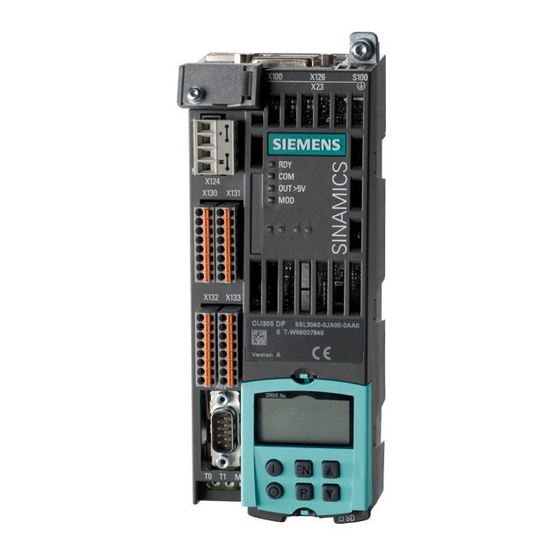
SINAMICS S110, an SMI motor, and the STARTER commissioning tool. Components SINAMICS S110 is a modular system that enables you to assemble your drive unit. The key components of the SINAMICS modular system are: ● Control Unit CU305 ●... - Page 12 Drive concept 1.2 Components The following picture shows a CU305 mounted on a Power Module 340 and an SMI motor: Figure 1-1 S110 on PM and SMI motor CU305 Control Unit X22, serial interface RS232 BOP20 (operator panel) Power Module 340 (PM) Interfaces X100 (DRIVE-CLiQ), X126 (CANopen or PROFIBUS), X23 (encoder) SMI motor (motor with integrated encoder and DRIVE-CLiQ interface) Power connection for motor...
-
Page 13: Requirements
Requirements Hardware and software components The example provided here involves creating a drive train with an SMI motor. The following components are required: ● Control Unit CU305 ● Power Module ● SMI motor (synchronous or induction motor) ● DRIVE-CLiQ cable ●... - Page 14 Requirements 2.1 Hardware and software components PC/PG Figure 2-1 Wiring the components DRIVE-CLiQ To assemble the drive unit components, wire the DRIVE-CLiQ cables as follows (for the wiring, see the example above): ● Attach the CU305 to the Power Module. Make sure that the CU305 is properly secured. ●...
-
Page 15: Creating The Drive Project Online
Creating the drive project ONLINE Creating the drive project ONLINE The following steps are required to create a drive object ONLINE: Table 3- 1 Creating a project ONLINE Step Activity Ensure that the commissioning requirements are fulfilled. Create a project with the help of a Wizard. Carry out an ONLINE search for DRIVE-CLiQ stations. -
Page 16: Creating Projects Online
Creating the drive project ONLINE 3.3 Creating projects ONLINE Creating projects ONLINE When you call up STARTER, the project Wizard is also called up by default. If an online help window is also displayed, you can close this as it is not needed. If the project Wizard is not called up, choose New with Wizard in the "Project"... - Page 17 Creating the drive project ONLINE 3.3 Creating projects ONLINE 3. In this example, we have selected the RS232 interface for communication. At this point, make sure that the communications interface is set to "Serial cable (PPI)". Figure 3-3 Project Wizard: selecting the interface If it is, choose Continue >.
- Page 18 Creating the drive project ONLINE 3.3 Creating projects ONLINE 5. The project Wizard carries out an ONLINE search for stations that can be accessed on the configured interface. The drives found are displayed. To confirm the drives and transfer them to the project, choose Continue >. Figure 3-5 Project Wizard: inserting a drive unit 6.
- Page 19 Creating the drive project ONLINE 3.3 Creating projects ONLINE Figure 3-7 Display of new project You have now created a new project, although it currently does not contain any data. In the next section, you will learn how to transfer the current configuration to the project. Getting Started Function Manual, 10/2008, 6SL3097-4AG10-0BP0...
-
Page 20: Transferring The Configuration
Creating the drive project ONLINE 3.4 Transferring the configuration Transferring the configuration Automatic drive configuration During initial commissioning, the CU305 is configured automatically and the factory settings are loaded. The SMI motor connected via DRIV-CLiQ is then recognized and the motor/encoder data read from this. - Page 21 Creating the drive project ONLINE 3.4 Transferring the configuration Figure 3-9 Comparing the configuration: Identical If no discrepancies are displayed, the configuration is synchronized. 3. Close the comparison window. 4. STARTER shows the Control_Unit and Drive_1 data that has been loaded in the project window under Configuration.
- Page 22 Creating the drive project ONLINE 3.4 Transferring the configuration 5. The motor can now be controlled using the STARTER control panel. The control panel is located under Drive_1, Commissioning and can be called up by double-clicking Control Panel in the tree structure. Figure 3-11 Calling up the control panel Getting Started...
-
Page 23: Operating The Drive With The Control Panel
Creating the drive project ONLINE 3.5 Operating the drive with the control panel Operating the drive with the control panel Control panel functions The control panel allows you to perform basic tasks for operating, monitoring, and testing the drive. Virtual START/STOP and JOG keys are available along with various diagnostic functions. - Page 24 Creating the drive project ONLINE 3.5 Operating the drive with the control panel 1. To assume control priority, choose the gray button Assume control priority! (This button is surrounded by a black border indicating that the field is active. This border appears throughout the following process to act as a guide.) Figure 3-13 Assume control priority...
- Page 25 Creating the drive project ONLINE 3.5 Operating the drive with the control panel Figure 3-15 Activate enable signals 1 4. When you choose Enables, they are automatically assigned (the color of the enable signals under "Diagnostics" changes and the Enables field is selected). On the control panel, the control buttons l/O for drive ON and OFF as well as jog mode for the drive become active (colored).
- Page 26 Creating the drive project ONLINE 3.5 Operating the drive with the control panel 5. The " n =" (speed) field is now active. Enter the speed in the now active n=..field and confirm this by choosing Enter. If the speed is preceded by a minus sign, the direction of rotation of the motor is reversed.
- Page 28 Siemens AG Änderungen vorbehalten Industry Sector © Siemens AG 2008 Drive Technologies Motion Control Systems Postfach 3180 91050 ERLANGEN GERMANY www.siemens.com/motioncontrol...