Husqvarna 326R Workshop Manual
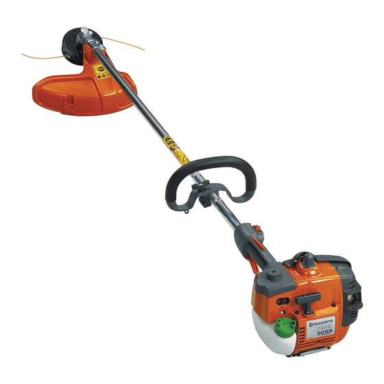
Trimmer
Hide thumbs
Also See for 326R:
- Operator's manual (36 pages) ,
- Operator's manual (40 pages) ,
- Operator's manual (40 pages)
Table of Contents
Advertisement
Advertisement
Chapters
Table of Contents

Related Manuals for Husqvarna 326R


Summary of Contents for Husqvarna 326R
- Page 1 Workshop manual 326R 326L 326C English...
-
Page 2: Table Of Contents
Workshop Manual Brushcutter, Trimmer Model 326R, 326L, 326C Contents General recommendations ______________________ 2 1. Starter ___________________________________ 3 2. Electrical system ___________________________ 7 3. Fuel system _____________________________ 13 4. Centrifugal clutch _________________________ 27 5. Angle gear _______________________________ 31 6. Cylinder and piston ________________________ 35 7. -
Page 3: General Recommendations
Operator’s Manual. The assembly of other equipment or accessories or spare parts not approved by Husqvarna can result in the failure to meet these safety demands and that the person carrying out assembly bears responsibility for this. -
Page 4: Starter
Starter Contents Dismantling ___________________________________ 4 Assembly ____________________________________ 4 Replacing the drive dogs ________________________ 6... - Page 5 Starter Dismantling Remove the 3 screws and lift off the starter. NOTE! Ensure the bushings (A) that guide the starter towards the fuel tank are not lost. 502 50 18-01 Offload the spring tension. Offload the spring tension. Remove the screw from the centre of Remove the screw in the centre of the the starter pulley and lift off the starter starter pulley.
- Page 6 Starter Assemble the starter handle. Assemble the starter handle. Tie a double knot and fold under the free end. Pull the knot fully into the handle. Tension the return spring. Pull out the Tension the return spring. starter cord fully and lift it out of the cut- Check the spring tension.
- Page 7 Starter Replacing the drive Replacing the drive dogs dogs Dismantle the drive body. Fit the piston stop no 502 54 15-01 in the spark plug hole and loosen the nuts holding the drive body. 502 54 15-01 Remove the circlip and replace any Remove the circlip holdings the drive damaged drive dogs or springs, if dog.
-
Page 8: Electrical System
Electrical system Electrical system Contents Checking the ignition spark __________________ 8 Dismantling ______________________________ 11 Assembly _______________________________ 12... - Page 9 Electrical system The engine is equipped with an electronic ignition system completely without moving parts. Consequently, a faulty component cannot be repaired, but must be replaced by a new component. The spark in an electronic ignition system has a very short burn time and can therefore be interpreted as weak and can be difficult to see while troubleshooting.
- Page 10 Electrical system If no spark occurs, disconnect the stop If no spark occurs even now, remove switch. the short-circuit cable from the connection point in the carburettor Replace the switch if necessary. compartment. If the plug now sparks, the fault is either in the stop switch or the short-circuit cable.
- Page 11 Electrical system Attach the ignition coil to the ignition Attach the ignition coil to the ignition cable. cable and ensure that the wire is folded along the cable. Slide the contact coil into the spark plug cover. TIP! Lubricate the hole in the spark plug cover so that it is easier to slide in the contact coil.
- Page 12 Electrical system Dismantling Dismantling Dismantle the starter, cylinder cover, The following components must be guard over the muffler and spark plug. dismantled for the ignition system to be accessible. Unhook the throttle cable from the carburettor. The cylinder cover, starter, guard over the muffler and spark plug.
- Page 13 Electrical system Fit the piston stop no. 502 54 15-01 Fit piston stop no. 502 54 15-01 in the and remove the nut holding the spark plug hole. flywheel. Remove the nut holding the flywheel. 502 54 15-01 NOTE! Position the piston stop so it is clamped between the piston crown and the combustion chamber.
-
Page 14: Fuel System
Fuel system Fuel system Contents Air filter ___________________________________ 14 Tank venting _______________________________ 15 Fuel filter __________________________________ 15 Fuel pump _________________________________ 16 Carburettor ________________________________ 16 Throttle ___________________________________ 23 Carburettor settings _________________________ 24... -
Page 15: Air Filter
Do not blow the filter clean with compressed air. It can be damaged. Ensure that the filter is dry before refitting it. TIP! Use Husqvarna’s cleaning agent Active Cleaning no. 505 69 85-70. 505 69 85-70 Impregnate the filter with air filter oil. -
Page 16: Tank Venting
Fuel system Tank venting Tank venting Check that the tank venting valve works Tank venting takes place through the correctly. fuel cap and needs to be functional for the engine to work. Replace the fuel cap if the valve is faulty. -
Page 17: Fuel Pump
Fuel system Fuel pump Fuel pump The fuel pump facilitates cold starts. The fuel pump has the task of facilitating the start of the engine when The pump cannot be repaired and must cold. The pump fills the carburettor with be replaced if it stops working. - Page 18 Fuel system The blending unit The blending unit Fuel and air are mixed here. In this section of the carburettor fuel and air are mixed in the proper proportions. The choke and throttle valves are placed here. In the middle of the venturi (narrowest part of the throughput) the main jet (D) is found.
- Page 19 Fuel system Pressure test the metering unit. Connect pressure tester 531 03 06-23 to the fuel hose nipple. Lower the carburettor in a vessel with petrol in order to discover any leaks more easily. Test the pressure at 50 kPa. No leakage is permitted.
- Page 20 Fuel system Remove the pump diaphragm. Remove the bolt holding the cover over the pump diaphragm. Check the diaphragm for damage. Lift off the cover (A), the gasket (B) and Remove the fuel screen and clean it or the diaphragm (C). attach a new one.
- Page 21 Fuel system Press out the main jet (A) with a Dismantle the main jet (A) and the plug suitable punch. (B). Remove the plug (B). Carefully drill a small hole (Ø 2 mm) in the plug and pry it up with a pointed object.
- Page 22 Fuel system • Mount the valves and dampers. Tip! Any numbers on the valves should be able to be read from the outside. Replace the fuel screen if it is damaged or cannot be cleaned. Place the pump diaphragm closest to the carburettor housing.
- Page 23 Fuel system Check that the carburettor is sealed. Connect pressure tester 531 03 06-23 to the fuel intake on the carburettor. No leakage is permitted at 50 kPa. Pump up the pressure to 50 kPa. Lower the carburettor in a vessel with petrol in order to discover any leaks more easily.
-
Page 24: Throttle
Fuel system Throttle Throttle Separate the engine body and the We recommend that the throttle is clutch cover. dismantled from the engine and shaft in order to efficiently carry out service and repair work. Separate the engine body and the clutch cover (see chapter ”Ignition system”). -
Page 25: Carburettor Settings
Fuel system Assembly of the throttle is done in the reverse order as set out for dismantling. Position the parts in the left-hand throttle half. Ensure the return spring (A) is facing the right way. Check that the throttle cable and the short-circuit cable are pressed correctly down in their channels so that they are not pinched when the two throttle... - Page 26 Fuel system Basic setting The carburettor is set to its basic setting when test run at the factory. The basic setting is “richer” than the optimal setting (fast idle speed is 600–800 rpm under the recommended max. speed) and should be kept during the engine’s first working hours.
- Page 27 Fuel system Carburettor adjustment under engine load When adjusting a carburettor fitted with carburettor needles with plastic sleeves with movement limiters, also called caps, both the carburettor needles H and L can only be adjusted within very tight limits to satisfy, among others, the stringent demands regarding the amount of hydrocarbons and nitrogen oxides in the exhaust fumes.
-
Page 28: Centrifugal Clutch
Centrifugal clutch Centrifugal clutch Contents Dismantling ________________________________ 28 Assembly _________________________________ 28 Replacing the clutch drum and drive axle ________ 29... - Page 29 Centrifugal clutch The centrifugal clutch has the task of transferring the power from the engine to the cutting equipment’s drive axle. As the name implies, it works according to a centrifugal principle. This means the clutch’s friction shoes are thrown outwards towards the clutch drum at a certain engine speed.
- Page 30 Centrifugal clutch Replacing the clutch Replacing the clutch drum and drive axle drum and drive axle Separate the shaft from the clutch Separate the shaft from the clutch cover. cover. Pull away the clutch cover complete Dismantle the clutch drum using tool with drive axle and clutch drum.
- Page 31 Centrifugal clutch...
-
Page 32: Angle Gear
Angle gear Angle gear Contents Dismantling ________________________________ 32 Assembly _________________________________ 33... - Page 33 Angle gear The angle gear has two purposes: The first is to gear down the engine’s high speed to better suit the lower speed a saw blade or trimmer requires to work efficiently. Secondly, the angle gear contributes towards the operator’s working stance so that it is comfortable and at the same time efficient.
- Page 34 Angle gear Dismantle the bearings from the output Dismantle the bearings from the output and input axles. and input axles with the help of a small bearing puller. TIP! Hold the bearing puller in a vice so that it gains a better grip around the bearing.
- Page 35 Angle gear...
-
Page 36: Cylinder And Piston
Cylinder and piston Cylinder and piston Contents Dismantling ________________________________ 36 Cleaning, inspection _________________________ 37 Analysis and actions _________________________ 38 Service tips ________________________________ 42 Wear tolerances ____________________________ 42 Assembly _________________________________ 43... -
Page 37: Dismantling
Cylinder and piston The cylinder and the piston are two of the components exposed to most strain in the engine. They must withstand, for example, high speeds, large temperature swings and high pressure. Moreover, they must be resistant to wear. Despite these tough working conditions, major piston and cylinder failure is relatively uncommon. -
Page 38: Cleaning, Inspection
Cylinder and piston Remove the gudgeon pin circlips. Remove the gudgeon pin circlips. Use small flat nose pliers and remove the gudgeon pin circlips. TIP! Keep your thumb over the circlip to prevent it from flying out. Dismantle the piston. Press out the gudgeon pin from the piston using the punch 505 38 17-05. -
Page 39: Analysis And Actions
For the best results we recommend Husqvarna two-stroke oil or ready-mixed fuel that is specially developed for air-cooled two-stroke engines. Mixing ratio: 1:50 (2%). If Husqvarna two-stroke oil is not available another good quality two-stroke oil can be used. Mixing ratio: 1:33 (3%) or 1:25 (4%). - Page 40 Cylinder and piston Piston scoring caused by heavy carbon deposits Too heavy carbon depositing can cause damage similar to that caused by insufficient lubrication. However, the piston skirt has a darker colour caused by the hot combustion gases that are blown past the piston. This type of piston damage starts at the exhaust port where carbon deposits can become loose and get trapped between the piston and the cylinder wall.
- Page 41 Cylinder and piston The guide pin for the piston ring has been pushed up Deep, irregular grooves caused by a loose circlip. Irregular grooves on the piston’s inlet side caused by through the top of piston. Shown here on the piston’s inlet side. a broken roller retainer.
- Page 42 Cylinder and piston Cause: Action: • Faulty air filter. Small dust particles Fit a finer grade filter. pass through the filter. • The filter is worn out due to too Check the filter carefully for holes and much cleaning, whereby small holes damage after cleaning.
-
Page 43: Service Tips
Cylinder and piston Service tips Defect: Action: Broken cooling fins, damaged threads or sheared bolts by In severe cases – replace the cylinder. the exhaust port. Repair the threads using Heli-Coil. Seizure marks in the cylinder bore (especially by the Polish the damaged area using a fine grade emery cloth exhaust port). -
Page 44: Assembly
Cylinder and piston Assembly Assembly Clean the crankcase. Clean the crankcase. Assemble the piston on the connecting Fit the piston on the connecting rod so rod. that the arrow on the piston points towards the exhaust port. Lubricate the gudgeon pin’s needle bearing with a few drops of engine oil. - Page 45 Cylinder and piston...
-
Page 46: Crankshaft And Crankcase
Crankshaft and crankcase Crankshaft and crankcase Contents Dismantling ________________________________ 46 Inspecting the crankshaft _____________________ 46 Assembly _________________________________ 47 Leakage testing the crankcase _________________ 48 Husqvarna E-Tech __________________________ 49... -
Page 47: Dismantling
Crankshaft and crankcase The task of the crankshaft is to transform the reciprocating motion of the piston to rotation. This requires a stable design withstanding immense pressure and rotational and bending strain, as well as high rotational speed. In addition the connecting rod is exposed to large acceleration and retardation forces as it moves between the top and bottom dead centres. -
Page 48: Assembly
Crankshaft and crankcase Check the crank bearing. Check the crank bearing. The connecting rod shall not have any radial play (up and down). It should, however, have axial play, in order to ensure good lubrication of the crank bearing among other things. Check the crankshaft’s bearing and Check for wear on the crankshaft’s sealing ring holder. -
Page 49: Leakage Testing The Crankcase
Crankshaft and crankcase Check that the guide rail and its A rail sits in the bottom of the gaskets are undamaged. crankcase and has the task of guiding the fuel-air mixture up towards and into the cylinder. Check that the gasket (A) which lies around the rail is undamaged and the gaskets (B) that are to seal against the cylinder. -
Page 50: Husqvarna E-Tech
Two-stroke oil (2%) Hydrocarbon (HC) Nitrous oxide (NO Husqvarna E-Tech Carbon monoxide (CO) Carbon dioxide (CO In 1996 Husqvarna presented a new, Particles (PM) improved two-stroke engine as a part Air consisting of: of the company’s efforts to produce 21% oxygen... - Page 51 Crankshaft and crankcase...
-
Page 52: Tools
List of tools Tools Contents Starter __________________________________ 52 Electrical system __________________________ 52 Fuel system _____________________________ 52 Centrifugal clutch _________________________ 52 Angle gear ______________________________ 53 Cylinder and piston ________________________ 53 Crankshaft and crankcase __________________ 53 Workshop equipment ______________________ 53... - Page 53 List of tools 502 50 18-01 502 51 91-01 502 50 18-01 531 00 60-76 502 50 64-01 502 54 15-01 502 71 13-01 502 50 64-01 502 50 83-01 502 52 16-01 502 51 34-02 501 60 02-03 502 50 06-01 505 69 85-70 502 54 15-01 531 00 48-63...
- Page 54 List of tools 502 54 11-02 502 51 03-01 503 97 64-01 502 50 18-01 503 80 17-01 505 38 17-05 503 84 40-01 531 03 06-23 531 03 06-23 502 71 14-01 505 69 85-70 101 64 23-48...
- Page 55 114 03 03-26 2004W38...