Table of Contents
Advertisement
Quick Links
1.0 Introduction
Unit must not be switched off during normal operation, the
product is designed to run continuously.
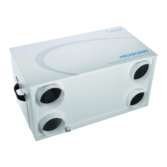
MRXBOX95LH1/LH2 is designed to provide mechanical
supply and extract ventilation with heat recovery.
The unit has the facility to commission the supply and extract
fans independently on minimum speed (continuous background
ventilation), boost control will control both fans to the same
volume.
To recover heat from the extract air the heat exchanger block
is utilised. This heat exchanger can recover up to 95% of the
normally wasted heat.
Figure 1. Airflow through unit.
Spigot 2.
Spigot 1.
Controls.
M20 & M16 cable
glands mains entry &
blanking gland.
Spigot Location and Ducting references
Spigot 1.
Extract air from kitchen/bathroom.
Spigot 2. Intake air from outside.
Spigot 3. Outside air to house.
Spigot 4. Extract air to outside.
Figure 2a. Mounting MRXBOX95-LH1/LH2 onto roof joists using the 'L' shaped fixing
brackets and AV mounts on the long side of unit.
Two fixing brackets
should be attached
on the control end of
the unit via the two
upper hole positions.
(see figure 2b).
Nuaire Limited Western Industrial Estate Caerphilly United Kingdom CF83 1NA
T: 029 2085 8400 F: 029 2085 8444 E: info@nuaire.co.uk W: www.nuaire.co.uk
MRXBOX95-LH1/LH2
Mechanical Ventilation Unit with
Heat Recovery for Loft Mounting
Installation and Maintenance
Spigot 4.
21.5mm Condensate drain
Spigot 3.
outlet. Optional either side.
2.0 Installation
Installation must be carried out by competent personnel in
accordance with the appropriate authority and conforming
to all statutory governing regulations.
All mains wiring must be in accordance with the current I.E.E.
Regulations, or the appropriate standards. Ensure that the
mains supply (Voltage, Frequency and Phase) complies with
the rating label.
Please note a clear working space is required around the
installed unit to allow the cover to be removed and provide
sufficient access for maintenance such as filter change.
The fan must be installed indoors, away from direct sources of
frost, heat, water spray or moisture generation.
The unit is designed for mounting on the roof joists in the loft
space using four "L shape" metal brackets and four A.V.
mounts supplied with the unit. Please note that various
positions for the brackets are available to suit different joist
centres.
Connect the four 'L' shape fixing brackets to the unit with the
M4 screws (provided) they can be attached to the long, or
short sides of the unit depending on requirements. Each pair of
brackets should be mounted at different heights so the fall is
towards the drip tray end of the unit. (see figures 2a, 2b and
2c for fixing details). Lower the unit with the "L" shape fixing
brackets attached onto the joists. Mark through the brackets
and drill four clearance holes into the top surface of joists.
Locate anti-vibration mounts (supplied) above and below each
bracket fixing point hole and, using 4 suitable screws (not
provided) and washers, fix the unit to the joists (see fig 2b).
Do not overtighten the fixings. The distance from the top
washer on the A.V. mount to the joist when installed must
not be less than 30mm.
Figure 2b. Side and front view example of
an 'L' shaped fixing bracket and AV mount
attached to ceiling joist.
Side view
Two fixing brackets
should be attached
on the non-control
end of the unit via
Metal bracket
the two lower hole
attached to unit
positions.
(see figure 2b).
1
The EMC Directive
2004/108/EC
The Low Voltage
Directive
2006/95/EC
Front view
Higher and lower
mounting hole positions
Washer Woodscrew
A. V. mount
Ceiling joist
14. 02. 14. Leaflet Number 671496
Advertisement
Table of Contents

Related Manuals for NuAire MRXBOX95-LH1


Summary of Contents for NuAire MRXBOX95-LH1
- Page 1 Spigot 4. Extract air to outside. Figure 2b. Side and front view example of Figure 2a. Mounting MRXBOX95-LH1/LH2 onto roof joists using the ‘L’ shaped fixing an ‘L’ shaped fixing bracket and AV mount brackets and AV mounts on the long side of unit.
-
Page 2: Installation And Maintenance
Installation cont. Figure 2d. Unit viewed from the front Figure 2c. Mounting MRXBOX95-LH1/LH2 onto roof joists using the ‘L’ shaped fixing brackets and AV mounts with four suitable screws on the short side of the unit. mounted at a slight angle. - Page 3 Figure 4. Typical MVHR ducted arrangement for a loft mounted unit using the Nuaire condensation trap 125mm dia. (CONTRAP 125). IMPORTANT: When using a “T” Piece to connect the CONTRAP drainage and the MVHR drain pipework the MVHR drain must Tile Vent.
-
Page 4: Dimensions (Mm)
Installation and Maintenance MRXBOX95-LH1/LH2 Mechanical Ventilation with Heat Recovery Figure 5. Main unit components shown with front and lid removed. G4 removable filter. Heat exchanger. Lid. G4 removable filter. Adjustment potentiometers and indication lights. Condensate Drain outlet. M20 & M16 Cable Glands. -
Page 5: Electrical Connection
Installation and Maintenance MRXBOX95-LH1/LH2 Mechanical Ventilation with Heat Recovery 4.0 Electrical Connection Electrical details:- Voltage: 240V 1ph 50Hz Consumption: LH1 - 1.3 Amp For good EMC engineering practice, any sensor cables LH2 - 2.2 Amp or switched live cables should not be... -
Page 6: Warranty
4 years. This warranty is conditional on planned maintenance being undertaken 10.0 Service Enquiries Nuaire can assist you in all aspects of service. Our service department will be happy to provide any assistance required, initially by telephone and If necessary arrange for an engineer to call. - Page 7 The equipment referred to in this Declaration of Incorporation is supplied by live are not prevented by the equipment panels or by fixed installation detail Nuaire to be assembled into a ventilation system which may or may not include (eg ducting), then guarding to the appropriate standard must be fitted.
- Page 8 CF83 1NA T: 029 2085 8400 F: 029 2085 8444 E: info@nuaire.co.uk W: www.nuaire.co.uk Technical or commercial considerations may, from time to time, make it necessary to alter the design, performance and dimensions of equipment and the right is reserved to make such changes without prior notice.
Need help?
Do you have a question about the MRXBOX95-LH1 and is the answer not in the manual?
Questions and answers