
Related Manuals for Festo IFB13-03


Summary of Contents for Festo IFB13-03
- Page 1 Valve terminal types 03/04-B Electronics manual Valve terminal with field bus connection PROFIBUS-DP 12 MBaud Type IFB13-03 Manual 163 958 en 0003c...
- Page 3 ....... . . 163 958 E (Festo AG & Co., D-73726 Esslingen, Federal Republic of Germany, 2000) Internet: http://www.festo.com E-Mail: service_international@festo.com...
- Page 4 Contents and general instructions Festo P.BE-VIFB13-03-EN en 0003c...
-
Page 5: Table Of Contents
........Summary of multifunctional Festo valve terminals . - Page 6 ..........Festo P.BE-VIFB13-03-EN en 0003c...
- Page 7 ............Festo P.BE-VIFB13-03-EN en 0003c...
-
Page 8: Designated Use
Please observe the standards specified in the relevant chapters and comply with technical regulations, as well as with national and local regulations. Festo P.BE-VIFB13-03-EN en 0003c... -
Page 9: Additional Modules For This Valve Terminal
Multi-I/O module with 12 inputs and 8 outputs, PNP VIAP-03-FB Analog I/O module with 1 input and 1 output VIAU-03-FB-... Analog I/O module with 3 inputs and 1 output Type voltage (-U) or current (-I) VIASI-03-M AS-Interface Master Festo P.BE-VIFB13-03-EN en 0003c... - Page 10 – Melsec A-Series/ Q- AJ71PB92D Series Fig. 0/1: List of possible controllers This manual includes the operation of the Festo valve terminal type 03/04-B in conjunction with the field bus protocol PRO- FIBUS-DP in accordance with EN 50170 (DIN 19245). Please note The valve terminal does not include the PROFIBUS-FMS protocol (no combi-slave functionality).
-
Page 11: Target Group
(PLC) and field bus systems. Service Please consult your local Festo repair service if you have any technical problems. Festo P.BE-VIFB13-03-EN en 0003c... -
Page 12: Important User Instructions
This means that there is a danger of damage to property if these instructions are not observed. In addition, the following pictogram marks passages in the text which describe activities involving electrostatically sensi- tive components: Electrostatically sensitive components: Incorrect handling may result in damage to the components. Festo P.BE-VIFB13-03-EN en 0003c... - Page 13 Pictograms Information: recommendations, tips and references to other sources of information. Accessories: information on necessary or useful accessories for the Festo product. Environment: information on the environmentally-friendly use of Festo products. Text markings The bullet denotes activities which can be carried out in any sequence.
-
Page 14: Abbreviations
Sub-base for double-solenoid valves or mid-position valves Input Output Input and/or output P-module General pneumatic module I/O module Module with digital inputs or outputs in general Programmable logic controller; in brief: controller Fibre-optical waveguide Fibre-optical waveguide Fig. 0/2: Index of abbreviations Festo P.BE-VIFB13-03-EN en 0003c... - Page 15 For most of the drawings in this manual, we have used a simplified representation of a type 03 valve terminal with four pneumatic sub-bases and four input/output modules (standard fitting). Input/output modules Field bus node Valves Fig. 0/3: Standard fitting for the drawings XIII Festo P.BE-VIFB13-03-EN en 0003c...
-
Page 16: Manuals For This Valve Terminal
Contents and general instructions Manuals for this valve terminal For complete documentation of the modular valve terminal the following Festo manuals are required in addition to your order and the subsequent expansion of your complete sys- tem: Festo designation Title/Product P.BE-MIDI/MAXI-03-... -
Page 17: Summary Of Components
Summary of components Chapter 1 Festo P.BE-VIFB13-03-EN en 0003c... - Page 18 1. Summary of components Contents Summary of multifunctional Festo valve terminals ....Description of components ........
-
Page 19: Summary Of Multifunctional Festo Valve Terminals
ISO 5588-2, fitted with pneumatic valves (single- solenoid, double-solenoid, mid-position) or cover plates – Components for high-level sub-bases (pressure regulator inter- mediate plates, restrictor plates etc.) Fig. 1/1: Summary of modules for the multifunctional Festo valve terminals Festo P.BE-VIFB13-03-EN en 0003c... -
Page 20: Description Of Components
Further modules (e.g. additional power Two green LEDs (one LED per input) supply, high-current outputs Input socket for one electric input PNP/NPN) (PNP or NPN) Green LED (per input) Fig. 1/2: Connecting and display elements on the electric modules Festo P.BE-VIFB13-03-EN en 0003c... -
Page 21: Type 03: Midi Pneumatic Modules
Yellow LEDs (per valve solenoid coil) Valve location inscription field (desig- nation signs) Manual override (per valve solenoid coil), either locking or non-locking Unused valve location with cover plate Fig. 1/3: Display and operating elements on the MIDI modules type 03 Festo P.BE-VIFB13-03-EN en 0003c... -
Page 22: Type 03: Maxi Pneumatic Modules
Manual override (per valve solenoid coil), either locking or non-locking Regulator for limiting the pressure of the auxiliary pilot air Unused valve location with cover plate Fig. 1/4: Display and operating elements on the MAXI modules type 03 Festo P.BE-VIFB13-03-EN en 0003c... -
Page 23: Type 04-B: Iso Pneumatic Modules
0.135 A fuse (per pilot solenoid) Yellow LEDs (per pilot solenoid 12) Adapter cable for power supply to the node and the I/O modules Fig. 1/5: Operating, display and connecting elements on the ISO modules type 04-B Festo P.BE-VIFB13-03-EN en 0003c... -
Page 24: Method Of Operation
– Internal control of the valve terminal Incoming field Continuing field Node Compressed air Work air (2, 4) Fig. 1/6: Summary of the functions of a valve terminal Festo P.BE-VIFB13-03-EN en 0003c... - Page 25 MIDI/MAXI valves or ISO valves on a node. Further information on their use can be found in the ”Pneu- matics manual” for your valve terminal. Festo P.BE-VIFB13-03-EN en 0003c...
- Page 26 1. Summary of components 1-10 Festo P.BE-VIFB13-03-EN en 0003c...
-
Page 27: Fitting
Fitting Chapter 2 Festo P.BE-VIFB13-03-EN en 0003c... - Page 28 Fitting the valve terminal onto a wall ....... Festo P.BE-VIFB13-03-EN en 0003c...
-
Page 29: Fitting The Modules And Components
(they are not resistant to bending, i.e. they will break off if bent backwards). – Electrostatically sensitive components Do not touch the contact surfaces of the plug connectors on the sides of the modules and components. Festo P.BE-VIFB13-03-EN en 0003c... -
Page 30: Earthing The End Plates
Remark: Instructions on earthing the complete valve terminal can be found in the chapter “Installation”. The diagram below shows how the end plates are fitted using as an example a type 03 valve terminal. Festo P.BE-VIFB13-03-EN en 0003c... - Page 31 2. Fitting Seals Ready-fitted earth cable Contact for the earth cable Fastening screws max. 1 Nm Fig. 2/1: Fitting the end plates (example of type 03 valve terminal) Festo P.BE-VIFB13-03-EN en 0003c...
-
Page 32: Fitting Onto A Hat Rail (Type 03)
In order to fit the valve terminal onto a hat rail, you will re- quire a hat-rail clamping unit. This must be fitted on the rear of the end plates as shown in the diagram below. Pay particu- lar attention to the following: Festo P.BE-VIFB13-03-EN en 0003c... - Page 33 After fitting: Fasten the lever with a locking screw (item 7). Lever Self-adhesive rubber foot O-ring Clamping elements Flat-head screw Locking screw *) Different lever lengths with MIDI and MAXI Fig. 2/2: Fitting the hat-rail clamping unit Festo P.BE-VIFB13-03-EN en 0003c...
- Page 34 (item 3) against unintentional loosening/opening. Hat-rail clamping unit unlocked Hat-rail clamping unit locked Locking screw Fig. 2/3: Fitting the type 03 valve terminal to a hat rail Festo P.BE-VIFB13-03-EN en 0003c...
- Page 35 *) Components for high-level linking: Weight see Pneumatics manual 2. Make sure that the mounting surface can support this weight. Check to see if you require support brackets for the I/O modules. 3. If necessary, use spacers. Festo P.BE-VIFB13-03-EN en 0003c...
- Page 36 (“blind hole”, see Pneumatics manual) – In the case of valve terminals with several I/O modules, use additional support brackets for the modules (approximately every 200 mm). Fig. 2/4: Possibilities for fitting onto a wall 2-10 Festo P.BE-VIFB13-03-EN en 0003c...
- Page 37 Installation Chapter 3 Festo P.BE-VIFB13-03-EN en 0003c...
- Page 38 Connection for fibre optic cable (FOC) ......3-29 Festo P.BE-VIFB13-03-EN en 0003c...
-
Page 39: General Connection Technology
– Electronics power supply (pin 1). – Load voltage supply to outputs/valves (pin 2). You will thereby avoid: – uncontrolled movements of loose tubing. – uncontrolled movements of the connected actuators – undefined switching states of the electronics. Festo P.BE-VIFB13-03-EN en 0003c... -
Page 40: Cable Selection For Field Bus Line
Calculation of power consumption, layout of power sup- ply unit: Chapter 3.3.1 “Calculation of power consump- tion” – Line length and cross section: Chapter 3.3 “Connection of power supply” – Determination of line length and cross section using tables or equations: Appendix A.2 Festo P.BE-VIFB13-03-EN en 0003c... -
Page 41: Connecting The Cable To The Plug/Sockets
After selecting a suitable cable, connect it to the plug/socket following the steps below: 1. Open the Festo plug/socket as follows (see figure): – Power supply socket: Insert the power supply socket into the power supply connection of the valve terminal. Unscrew the socket housing. - Page 42 Connector/socket (straight or angled): – Power supply socket PG7, 9 or 13.5 – Sensor plug – Bus cable socket PG7, 9 or 13.5 Cable Strain relief Housing Connection socket Plug Socket Fig. 3/1: Plug/socket components and cable guides Festo P.BE-VIFB13-03-EN en 0003c...
- Page 43 5. Connect the cable ends. 6. Insert the connection socket back in the housing of the plug/socket and screw both parts together. Pull the cable back until there are no loops within the housing. 7. Tighten the strain relief. Festo P.BE-VIFB13-03-EN en 0003c...
-
Page 44: Bus Nodes
Caution The nodes contain electrostatic sensitive devices. S Do not therefore touch any contacts. S Observe the regulations for handling electrostatically sensitive components. You will then prevent the electronics in the node from being damaged. Festo P.BE-VIFB13-03-EN en 0003c... - Page 45 Closing: Replace cover. Insert the operating voltage connec- tion cable back into the housing so that it is not trapped any- where. Tighten the cover screws in diagonally opposing se- quences. Tighten the screws on the Sub-D plug. Festo P.BE-VIFB13-03-EN en 0003c...
-
Page 46: Configuring The Valve Terminal
Screening plate Board 1 Plug for field bus line Fig. 3/3: Connection, display and control components of the node Please note Boards 2 and 3 are connected. They can only be removed or inserted together. 3-10 Festo P.BE-VIFB13-03-EN en 0003c... -
Page 47: Setting Profibus Addresses And Voltage Monitoring
The DIL switch consists of four switching elements. These are numbered from 1...4. The position ON is marked. Hundred addresses DIL switch (Station-No.) 0...99 100...125 DIL switch Voltage monitoring active inactive DIL switch Reserved Fig. 3/4: Settings of DIL switch 3-11 Festo P.BE-VIFB13-03-EN en 0003c... - Page 48 Please note The PROFIBUS addresses (DP-slave addresses) of the valve terminals cannot be modified by the DP master. The valve terminals can only be addressed by the PROFIBUS address set on the address selector switches. 3-12 Festo P.BE-VIFB13-03-EN en 0003c...
-
Page 49: Overview Of Possible Profibus Addresses
2. Assign an as yet unassigned PROFIBUS address to the valve terminal. 3. Use a screwdriver to set the arrow of the relevant address selector switch or DIL switch 1 to the units, tens or hundreds figure of the desired PROFIBUS address. 3-13 Festo P.BE-VIFB13-03-EN en 0003c... - Page 50 UNITS Example 2 PROFIBUS ad- dress set: 121 TENS TENS HUNDREDS HUNDREDS Fig. 3/7: Example of PROFIBUS addresses set Please note Check whether you want the configuration data displayed before you close the node cover. 3-14 Festo P.BE-VIFB13-03-EN en 0003c...
-
Page 51: Field Bus Baud Rate And Field Bus Length
3. Installation 3.2.5 Field bus baud rate and field bus length Please note The Festo valve terminal type 03/04-B automatically sets itself to the correct baud rate. The maximum field bus length depends on the baud rate used. The table below shows the baud rates which can be used. -
Page 52: Switching On The Power Supply
EN 60950/VDE 0805. Remark: By using PELV power units with Festo valve terminals, you can ensure protection against electric shock (protection against direct and indirect contact) in accordance with EN 60204-1/IEC 204. -
Page 53: Calculating The Current Consumption
The table below shows you how to calculate the complete current consumption for the valve terminal. The values speci- fied have been rounded up. If you wish to use other valves or modules, please refer to the relevant technical specifications for their current consumption. 3-17 Festo P.BE-VIFB13-03-EN en 0003c... - Page 54 ____ x 0.100 A Load current of simultaneously actuated high-current output modules ____ x _____ A Current consumption of high-current outputs *) per additional supply module max. 25 A Fig. 3/8: Calculating the complete current consumption 3-18 Festo P.BE-VIFB13-03-EN en 0003c...
-
Page 55: Connecting The Power Supply
EMERGENCY STOP (e.g. switching off the load voltage for the valves and output modules, switching off the pres- sure). 3-19 Festo P.BE-VIFB13-03-EN en 0003c... - Page 56 Check the 24 V load voltage of the outputs while your system is operating. Make sure that the load voltage of the outputs lies within the permitted tolerance even during operation at full load. Recommendation: Use a closed-loop power unit. 3-20 Festo P.BE-VIFB13-03-EN en 0003c...
- Page 57 4 have the same potential and that there are no equalizingcurrents. You can thereby avoid interference due to electromagnetic influences and you can ensure electromagnetic compatibil- ity in accordance with the EMC guidelines. 3-21 Festo P.BE-VIFB13-03-EN en 0003c...
- Page 58 24 V DC 10 % must be ob- served. – both connections are connected for potential equalization and that equalizing currents are avoided. – the load voltage at pin 2 (valves/electric outputs) can be switched off separately. 3-22 Festo P.BE-VIFB13-03-EN en 0003c...
- Page 59 Load voltage can be switched off separ- ately. Earth connection pin 4 designed for 12 A External fuses Potential equalization Fig. 3/11: Example – connection of a common 24 V power supply and the potential equal- ization(example for type 03) 3-23 Festo P.BE-VIFB13-03-EN en 0003c...
-
Page 60: Connecting The Profibus Dp Interface
3. Installation Connecting the PROFIBUS DP interface Please note Please note that only the Festo plug conforms to protection class IP 65. There is a sub-D connection on the node for connecting the valve terminal to the PROFIBUS-DP. This connection is used for the incoming cable, as well as for the continuing field bus cable. - Page 61 S Replace the two flat screws with bolts (part no. 340960). Please note If the valve terminal is fitted moveably in a machine, the field bus cable on the moving part of the machine must be fitted with a strain relief. 3-25 Festo P.BE-VIFB13-03-EN en 0003c...
-
Page 62: Screening/Shield Connection
Fig. 3/13: Festo plug (shown enlarged) Please note The cable clip in the Festo plug is connected internally only capacitively with the metallic housing of the sub-D plug. This is to prevent equalizing currents flowing through the screening of the field bus cable (see diagram). -
Page 63: Bus Connection With Terminating Resistors
Recommendation: For this purpose use the ready-to-use sub-D plug from Festo (designation: FBS-SUB-9-GS-9). A suitable resistor network is incorporated in the housing of the Festo sub-D plug. The bus termination must be switched manually. Bus. termination switched on switched on Fig. - Page 64 Pin 6 plug Supply voltage 390 W Pin 3 RxD/TxD-P 220 W Pin 8 RxD/TxD-N 390 W Pin 5 DGND Fig. 3/15: Circuit diagram of bus termination network for line type A as per EN 50170 3-28 Festo P.BE-VIFB13-03-EN en 0003c...
-
Page 65: Connection For Fibre Optic Cable (Foc)
Example for optical fibre waveguide network components: – Siemens Optical Link Module (OLM) for PROFIBUS plus – Siemens Optical Link Module (OLM) for PROFIBUS 3-29 Festo P.BE-VIFB13-03-EN en 0003c... - Page 66 3. Installation 3-30 Festo P.BE-VIFB13-03-EN en 0003c...
- Page 67 Commissioning Chapter 4 Festo P.BE-VIFB13-03-EN en 0003c...
- Page 68 ........4-45 4.3.3 Information for commissioning (general DP master) ....4-45 Festo P.BE-VIFB13-03-EN en 0003c...
-
Page 69: Addressing And Configuring The Valve Terminal
With this valve terminal, the assignment of the valve addresses can be set fixed by means of a DIL switch in the adapter block. This manual valve terminal configur- ation (“Address reserving”) is described in the Appendix of the Pneumatics manual for type 04-B. Festo P.BE-VIFB13-03-EN en 0003c... - Page 70 **) The status bits are assigned automatically within the terminal, as soon as there are input modules. Fig. 4/1: Number of assigned I/Os per module Copy the following table for further calculations. Festo P.BE-VIFB13-03-EN en 0003c...
- Page 71 11. b) If not: round up to the next half byte (+1...3). 11.Number of 4-output electric modules ________ x 4 12.Number of other outputs, e. g. multi I/O module Total number of outputs to be configured Festo P.BE-VIFB13-03-EN en 0003c...
-
Page 72: Address Assignment Of The Valve Terminal
– lower-value address: pilot solenoid 14 – higher-value address: pilot solenoid 12 Information on reserving addresses of the valves on the type 04-B valve terminal can be found in the Pneumatics manual for type 04-B. Festo P.BE-VIFB13-03-EN en 0003c... - Page 73 If the number of valve addresses cannot be divided by 4 without remainder, you must round up to 4 bits because of the 4-bit orientated addressing. The bits thus rounded up in the address range cannot be used. Festo P.BE-VIFB13-03-EN en 0003c...
- Page 74 – The status bits are only available if input modules are connected to the valve terminal and are configured – Addressing The status bits are transmitted to the four highest- value positions of the configured address range. Festo P.BE-VIFB13-03-EN en 0003c...
- Page 75 (see address 3 or Fig. 4/1). – if unused valve locations are fitted with cover plates, the addresses will still be assigned (see addresses 12, 13). Festo P.BE-VIFB13-03-EN en 0003c...
- Page 76 – The maximum possible amount of equipment which can be fitted on the valve terminal is limited by the addres- sing limits of the relevant field bus protocol and the mechanical limits of the valve terminal (max. 96 inputs or 48 outputs). 4-10 Festo P.BE-VIFB13-03-EN en 0003c...
-
Page 77: Address Assignment After Extension/Conversion
– when existing input/output modules are removed or replaced by input/output modules which occupy fewer or more input/output addresses. If the configuration of the inputs is modified, the addresses of the status bits may be shifted. 4-11 Festo P.BE-VIFB13-03-EN en 0003c... - Page 78 No rounding Fig. 4/3: Address assignment of a valve terminal with digital I/Os after extension (example type 03) Remarks on the diagram Pressure supply modules and intermediate pressure supply modules do not occupy any addresses. 4-12 Festo P.BE-VIFB13-03-EN en 0003c...
-
Page 79: Siemens: Bus Configuration And Addressing
The following chapters describe as an example the most im- portant steps required for configuring the Festo valve ter- minal with the COM PROFIBUS software or with STEP 7. In the following, it is assumed that the user is already familiar with the contents of the manual for the COM PROFIBUS software or for STEP 7. -
Page 80: Information For Commissioning
ACTUAL configuration. 4.2.2 Information for commissioning Please note Take into account the following points. This ensures reli- able operation of your application with the Festo valve terminal. – Interface IM 308-C, CP xx, ... on the correct module slot of the automation device. - Page 81 Function and position of status bits, see Chapter 5. Diag- nosis/troubleshooting. FREEZE and SYNC The method of accessing the commands FREEZE and SYNC depends on the controller used. Please refer to the docu- mentation for your field bus module. 4-15 Festo P.BE-VIFB13-03-EN en 0003c...
- Page 82 “frozen”. The valve terminal then no longer reacts to modifi- cations to the output image in the master. The following FREEZE command accepts the updated output image of the master. Return to normal operation with the command UNSYNC. 4-16 Festo P.BE-VIFB13-03-EN en 0003c...
- Page 83 The DP identifiers can be entered via a dialog or directly into the configuration tables of the configuration program. The method depends on the configuration program. The following table shows a summary of the possible entries for the valve terminal: 4-17 Festo P.BE-VIFB13-03-EN en 0003c...
- Page 84 — 8DO, 8DO, 8DO, 8DO, 8DO, up to 56 — — up to 64 — — up to 72 — — up to 80 — — Fig. 4/4: Possible configurations of the inputs and outputs 4-18 Festo P.BE-VIFB13-03-EN en 0003c...
- Page 85 = Total length *) not supported Fig. 4/5: Structure of the identifier bytes The structure of a DP identifier is described in the following overview: Example: 00010000 = 016 (010 ): 8DI = 8 digital inputs 4-19 Festo P.BE-VIFB13-03-EN en 0003c...
- Page 86 If the terminal has more than 56 IO, use the common identifier. When using common identifiers, comply with the following sequence: 1. Identifier “0”: Digital inputs 2. Identifier “1”: Digital outputs 4-20 Festo P.BE-VIFB13-03-EN en 0003c...
- Page 87 – in the manual for the configuration program Copy the provided DMF or type file into the relevant directory of your configuration program. The following screen shots show various examples of options: – Station selection – Configuration. 4-21 Festo P.BE-VIFB13-03-EN en 0003c...
-
Page 88: Preparations For Com Profibus 3.X And
3. After selecting the master/host system, process the mask “Bus parameter” in the menu “Configure” – Bus profile – Baud rate Further information (directories, etc.) can be found in the file “readme” in the main directory of the CD ROM. 4-22 Festo P.BE-VIFB13-03-EN en 0003c... -
Page 89: Station Selection With Com Profibus
The slave type “VALVES” appears when you copy the Device data base (see step 1 of the preparations). 2. Move the mouse to the left and click below the graphic 2. The mask “PROFIBUS address” appears 3. 4-23 Festo P.BE-VIFB13-03-EN en 0003c... - Page 90 (see chapter 3.2.4) in the slave and confirm this. The mask “Slave Parameters” appears 4. 4. Select the station type “FESTO type 03 FB13” and confirm this. The symbol of the Festo valve terminal appears under the graphic of the master.
- Page 91 Enter under “ID”: – for each 8 inputs: – for each 8 outputs: Fig. 4/7 shows an overview of the possible configurations depending on the number of inputs/outputs. Comply with the configuration rules in Chapter 4.1. 4-25 Festo P.BE-VIFB13-03-EN en 0003c...
- Page 92 3. “Format” 4 Select “Byte” for the configuration of the inputs and out- puts. The setting “ Word” is not permitted. 4. “Module consistency” 5 Do not select this field. See Chapter 4.2.7 – Address assignment 4-26 Festo P.BE-VIFB13-03-EN en 0003c...
-
Page 93: Station Selection With Com Profibus
4.2.5 Station selection with COM PROFIBUS 5.0 Fig. 4/8: Station selection with COM PROFIBUS 5.0 Proceed as follows: 1. Open the directory in the hardware catalogue \DP slave\valves\... 1 The Festo valve terminals are listed. (Prerequisite: You have 4-27 Festo P.BE-VIFB13-03-EN en 0003c... - Page 94 (see above) Configuring Access the mask “Configure”: 1. Click with the right-hand mouse button on the symbol of the Festo valve terminal. Click on “Configure” in the menu which now appears. The mask “Configure” appears (Fig. 4/9). 4-28 Festo P.BE-VIFB13-03-EN en 0003c...
- Page 95 Enter under “Identifier”: – for each 8 inputs: – for each 8 outputs: Fig. 4/7 shows an overview of the possible configurations depending on the number of inputs/outputs. Comply with the configuration rules in Chapter 4.1. 4-29 Festo P.BE-VIFB13-03-EN en 0003c...
- Page 96 Do not select this field. This sets the format “Byte” for the configuration of the digital inputs and outputs. The set- ting “ Word format” is not permitted. 4. “Consistency” 5 Do not select this field. 4-30 Festo P.BE-VIFB13-03-EN en 0003c...
-
Page 97: Configuration Examples For Com Profibus
Coils 9-12 plus 4O unused (rounded up) Fig. 4/10: Example 1 - Configuration The 4 status bits in this case increase the number of inputs to 32 (24I + 4I unused + 4 status bits). 4-31 Festo P.BE-VIFB13-03-EN en 0003c... - Page 98 Valve terminal with 3 x 8-input modules, + 12 single-solenoid valves: Comment ident- ifier 32 DI 1.-3. Input module plus 4I reserve plus 4I status (019) bits 16 DO Coils 1-12 plus 4O reserve (rounded up) (033) Fig. 4/12: Example 3 - Configuration 4-32 Festo P.BE-VIFB13-03-EN en 0003c...
-
Page 99: Address Allocation Of Inputs And Outputs
The function “Autoaddress” carries out, in the case of a marked I/O address range, an automatic assignment of the free addresses of the system depending on the system limits. This concludes the configuration/address allocation with COM PROFIBUS. 4-33 Festo P.BE-VIFB13-03-EN en 0003c... - Page 100 This software enables you to ascertain the PROFIBUS con- figuration with the aid of a graph. Further information (directories, etc.) can be found in the file “readme” in the main directory of the CD ROM. 4-34 Festo P.BE-VIFB13-03-EN en 0003c...
-
Page 101: Step 7 V4.X / V 5.0 - Hardware Configurator
Device data base having an error. Please inform yourself about handling the station Device data bases in the STEP 7 help. 2. Process the mask Features of the “DP Master” – Bus profile – Baud rate 4-35 Festo P.BE-VIFB13-03-EN en 0003c... - Page 102 “Extras” - “Install new GSD” - File type “Bitmap” in the Hardware config. Further information (directories, etc.) can be found in the file “readme” in the main directory of the CD ROM. 4. Activate the DP master in the rack. 4-36 Festo P.BE-VIFB13-03-EN en 0003c...
- Page 103 4. Commissioning Station selection STEP 7 Fig. 4/14: Station selection with STEP7 4.x / 5.0 – Hardware Config. (The masks shown are not all visible at the same time, see text) 4-37 Festo P.BE-VIFB13-03-EN en 0003c...
- Page 104 4. Commissioning 1. Click on the catalogue symbol 1. This opens the Hard- ware catalogue. 2. In the hardware catalogue mark the station type “FESTO type 03 FB13” 2 (\PROFIBUS-DP\Additional FIELD DE- VICES\VALVES) with the left-hand mouse button. The slave type “VALVES” appears under folder “Addi- tional FIELD DEVICES ”when you copy the Device data...
- Page 105 Fig. 4/15: Configuration with STEP 7 – Hardware catalogue (for captions see text) In STEP 7, the common identifier is used for configuring the valve terminal. Assign the DP identifiers in ascending order without gaps. No field may remain unused. Enter inputs before outputs 4-39 Festo P.BE-VIFB13-03-EN en 0003c...
- Page 106 2. Click on the catalogue symbol. This opens the Hardware catalogue. 2 3. Open the folder \PROFIBUS-DP\ Additional FIELD DEVICES\VALVES\FESTO type 03 FB13 3 4. Mark the required number of input bytes (see Chapter 4.2) with the left-hand mouse button and drag the entry to line “0”...
- Page 107 DP identifier line 1 in the configuration table of the DP slave and change the start address of the outputs. Please note The S7-400 controllers always reserve 4 bytes of ad- dresses per DP identifiers. 4-41 Festo P.BE-VIFB13-03-EN en 0003c...
- Page 108 Local: DO 2 byte 34...35 Fig. 4/17: Example 2– Configuration 8 10 * unused Fig. 4/18: Addressing (example 2) Program O34.4 “Output = O0.04 (4th valve, right coil) O35.3 “Output = O0.011 (7th valve, left coil) 4-42 Festo P.BE-VIFB13-03-EN en 0003c...
- Page 109 O0.05 (4th valve, left coil) I55.4 “Input I1.12 (4th input stage, 5th input) O53.0 “Output O0.08 (6th valve, right coil) O54.6 “Output O1.06 (2nd output stage, 3rd output) This concludes the configuration/address allocation with STEP 7. 4-43 Festo P.BE-VIFB13-03-EN en 0003c...
-
Page 110: General Dp Master: Bus Configuration And Addressing
4. Commissioning General DP master: Bus configuration and addressing The Festo valve terminal type 03/04-B can be controlled by any PLC, PC or industrial PC with a PROFIBUS-DP module in accordance with EN 50170 (DIN 19245). 4.3.1 General commissioning instructions Before commissioning or programming, compile a configur- ation list of all connected field bus stations. -
Page 111: Switching On The Power Supply
– The 4 status bits always increase the number of inputs to be configured by +4. – Valve terminals without inputs do not have status bits. Function and position of status bits, see Chapter 5. Diag- nosis/error handling. 4-45 Festo P.BE-VIFB13-03-EN en 0003c... - Page 112 1. send a parametrizing telegram 2. send a configuration telegram 3. request diagnostic information 4. start cyclic exchange of user data The composition and contents of the individual telegrams are described in the following chapters. 4-46 Festo P.BE-VIFB13-03-EN en 0003c...
- Page 113 “1”: Activate SYNC Unlock_Req Bit 7 Bit 6 Explanation Lock_Req min T + valve terminal parameter may be overwritten Valve terminal released for other masters Valve terminal locked for other masters Valve terminal released for other masters 4-47 Festo P.BE-VIFB13-03-EN en 0003c...
- Page 114 The configuration of a valve terminal can be carried out as follows: – one identifier byte for each nx8 inputs one identifier byte for each nx8 outputs – one identifier byte each for the sum of the inputs and the sum of the outputs. 4-48 Festo P.BE-VIFB13-03-EN en 0003c...
- Page 115 4. Commissioning Summary of parameters (Chk_Cfg): Octet 1-n: Identifier bytes Permissible identifiers for Festo valve terminals: Number of I/Os Valve terminal I/Os Inputs Outputs Decimal Hex. Decimal Hex. up to up to 16 up to 24 up to 32 up to 40...
- Page 116 Bit 0: Input/output x*) Bit 1: Input/output x+1 . . . Bit 7: Input/output x+7 Octet 2: I/O data byte_2 Bit 0: Input/output x+8 Bit 1: Input/output x+9 . . . Bit 7: Input/output x+15 4-50 Festo P.BE-VIFB13-03-EN en 0003c...
- Page 117 Bit 7: Input/output z+7 . . . Octet 8: I/O data byte_8 Bit 0: Input/output t+8 Bit 1: Input/output t+9 . . . Bit 7: Input/output t+15 *) x, y, z, t = address offset of master module 4-51 Festo P.BE-VIFB13-03-EN en 0003c...
- Page 118 Octet 3 (bits) Octet 1 (bits) Octet 2 (bits) Octet 3 (bits) Octet 2 Octet 1 Incoming user data from DP master Outgoing user data for the master (bold = status bits) Fig. 4/21: Example – Addressing 4-52 Festo P.BE-VIFB13-03-EN en 0003c...
- Page 119 Destination SAP (DSAP) Data_Exchange RD_Inp RD_Outp Slave_Diag Set_Prm Chk_Cfg Get_Cfg Global_Control Set_Slave_Add Fig. 4/22: Functions and SAPs Bus parameter/reaction times Baud rate max T max T (kBit/s) ...187.5 1500 3000 6000 12000 Fig. 4/23: Reaction times 4-53 Festo P.BE-VIFB13-03-EN en 0003c...
- Page 120 “frozen”. The valve terminal then no longer reacts to modifi- cations to the output image in the master. The following SYNC command causes the updated output image of the master to be accepted. Return to normal operation UNSYNC command. 4-54 Festo P.BE-VIFB13-03-EN en 0003c...
- Page 121 You can configure max. 7 identifiers. Individual identifiers must correspond to the existing valve terminal structure. – Additional inputs/outputs as reserve are not permitted. – If identifiers for specific modules are not used, enter the next identifier. 4-55 Festo P.BE-VIFB13-03-EN en 0003c...
- Page 122 Valve terminal with 44 inputs, 16 solenoid coils, 8 electrical outputs. Configuration: Configured Number of Consistency Identifier I/Os bytes 44 inputs 6 (DI) 1 Byte + 4 status bits 16 solenoid 3 (DO) 1 Byte coils 8 outputs 4-56 Festo P.BE-VIFB13-03-EN en 0003c...
- Page 123 Diagnosis and error treatment Chapter 5 Festo P.BE-VIFB13-03-EN en 0003c...
- Page 124 Type 04-B: fuses for the pilot solenoids ......5-38 Festo P.BE-VIFB13-03-EN en 0003c...
-
Page 125: Summary Of Diagnostic Options
Advantage Faster access to error Faster “on the spot” error Detailed error detection messages detection Detailed de- Chapter 5.4 Chapter 5.2 Chapter 5.5 scription Fig. 5/1: Options for diagnosis and error handling Festo P.BE-VIFB13-03-EN en 0003c... -
Page 126: Diagnosis On The Spot
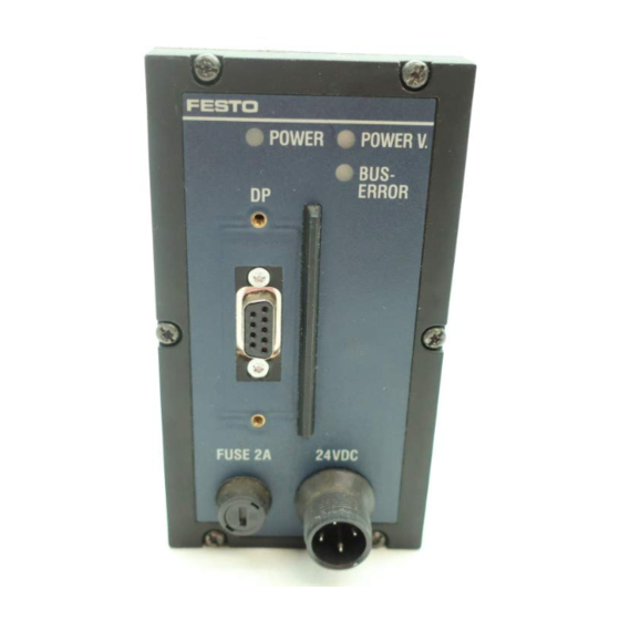
The LEDs on the node cover provide information about the operating status of the valve terminal: Green LED (oper- ating status dis- play) Green LED Red LED (error display) POWER POWER V BUS ERROR Fig. 5/2: LEDs of node Festo P.BE-VIFB13-03-EN en 0003c... - Page 127 Operating voltage of outputs (valves, electrical outputs) < 21.6 V. Operating voltage of outputs (valves, electrical outputs) < 10 V. Flashing green Flashing red Green lit up Red lit up Fig. 5/3: LED displays for operating status (POWER LEDs) Festo P.BE-VIFB13-03-EN en 0003c...
- Page 128 > 12 – Only use permitted module – Module type not permitted types Hardware error Servicing required Flashing green Flashing red Green lit up Red lit up Fig. 5/4: LED displays for operating status (BUS ERROR) Festo P.BE-VIFB13-03-EN en 0003c...
-
Page 129: Leds Of The Valves
There is a yellow LED for each valve solenoid coil on the valve terminal. This shows the switching status of the valve sole- noid coil. Valve terminal type LEDs of the valve solenoid coils Type 03 Type 04-B Fig. 5/5: Positions of the valve solenoid coil LEDs Festo P.BE-VIFB13-03-EN en 0003c... - Page 130 Short circuit/overload (only type 04-B) The valve solenoid coils of valve terminal type 04-B are fitted with special fuses for protection against short circuit or over- load. The method of replacing these fuses is described in chapter 5.8. Festo P.BE-VIFB13-03-EN en 0003c...
-
Page 131: Leds Of The Input/Output Modules
(error display of the digital outputs). The signal currently at the relevant input or output is shown by means of the yellow and green LEDs. The red LEDs of the outputs display a short circuit/overload at the relevant out- put. Festo P.BE-VIFB13-03-EN en 0003c... - Page 132 0 (no signal) of the outputs red alight logical 1 (signal present) *) Treatment of short circuit/overload see “Supplementary description of the I/O modules” Fig. 5/7: LED displays of the input/output modules 5-10 Festo P.BE-VIFB13-03-EN en 0003c...
-
Page 133: Test Routines
All the outputs are switched on/off sequentially at 1-second intervals. Display configuration data Number of individual input and out- put bytes by flashing the LEDs POWER V and BUS ERROR Fig. 5/8: Adjustable test routines 5-11 Festo P.BE-VIFB13-03-EN en 0003c... - Page 134 Fig. 5/9: Setting the test routines 8. Start: Set DIL switch element 1 to OFF. If faults occur when the test routine is started, the red LED on the node will flash quickly. The procedure must then be re- peated. 5-12 Festo P.BE-VIFB13-03-EN en 0003c...
- Page 135 “Display of configuration data”. – Stopping the test routine: Operating voltage OFF – The “display of the configuration data” is continual. – The sequence of flashing signals is shown in the following diagram. 5-13 Festo P.BE-VIFB13-03-EN en 0003c...
- Page 136 Number of input bytes AS-i Number of output bytes AS-i Number of input words analog Number of output words analog New run of test routine cycle Operating voltage OFF: End of test routine 5-14 Festo P.BE-VIFB13-03-EN en 0003c...
-
Page 137: Status Bits
“logic zero”. The position of the 4 status bits within the address space of the valve terminal can be found in the following chapters on diagnosis with the relevant field bus protocol. 5-15 Festo P.BE-VIFB13-03-EN en 0003c... - Page 138 *) The status bits can always be addressed at the four highest value addresses of the configured address space. **) only when the voltage monitoring is activated (see Chapter 3.2.3, DIL switch) Fig. 5/10: Coded diagnostic information of the 4 status bits 5-16 Festo P.BE-VIFB13-03-EN en 0003c...
- Page 139 VIGE-03-FB-8-S) A-Bit Error at AS interface or hard- Diagnostic group information ware error on analog module on AS interface/analog IO mod- ules Electronic fusing of input module available since February 1999. Fig. 5/11: Diagnostic information 5-17 Festo P.BE-VIFB13-03-EN en 0003c...
-
Page 140: Short Circuit/Overload
Output modules – High-current output modules – Multi-I/O modules – Input modules – Input modules with fuses The behaviour of these modules during short circuit/overload is described in the “Supplementary description of the I/O modules”. 5-18 Festo P.BE-VIFB13-03-EN en 0003c... -
Page 141: Diagnosis Via Profibus-Dp (Dp Standard)
The identifier or channel-related diagnosis listed in EN 50170 (DIN 19245) is not supported. The valve terminal type 03/04-B provides the following diag- nostic information in accordance with DIN 19245, Part 3. 5-19 Festo P.BE-VIFB13-03-EN en 0003c... - Page 142 The valve terminal replies with an octet string of length 15. Diagnosis options via PROFIBUS-DP The Festo valve terminal offers extensive diagnostic options via the PROFIBUS-DP. The diagram below shows you the steps required for diagnosing the valve terminal. Only the diagnostic bits, which require a further diagnostic step, are represented.
-
Page 143: Summary Of Diagnostic Bytes
Device-related diagnosis 4 – Error bits AS-i bus slave 0-7 Device-related diagnosis 5 – Error bits AS-i bus slave 8-15 Device-related diagnosis 6 – Error bits AS-i bus slave 16-23 Device-related diagnosis 7 – Error bits AS-i bus slave 24-31 5-21 Festo P.BE-VIFB13-03-EN en 0003c... -
Page 144: Diagnostic Information
“1”: Valve terminal does not support requested func- tion Diag.Invalid_Slave_Response always log. “0” (set by valve terminal) Diag.Prm_Fault Last parametrization telegram faulty Diag.Master_Lock always log. “0” (set by valve terminal) bold = valve terminal related bits 5-22 Festo P.BE-VIFB13-03-EN en 0003c... - Page 145 “0” (set by valve terminal) bold = valve terminal related bits Structure of station status 3 Octet 3: Station status_3 Meaning Explanation 0...6 – Reserved Diag.Ext_Diag_Overflow always log. “0” (set by valve terminal) 5-23 Festo P.BE-VIFB13-03-EN en 0003c...
- Page 146 5...6 Ident_Number Manufacturer identification: These octets contain the manufacturer identification: FB13 for the Festo valve terminal type 03/04-B. Ext_Diag_Data Header device-related diagnosis: (device-related diagnosis) This octet represents the header for the device diag- nosis. The valve terminal enters the fixed value 8 in this octet, i.e.
- Page 147 (see Chapter 3.2.3, DIL switch) Structure of device-related diagnosis 2 Octet 9: Device-related diagnosis 2 Meaning Explanation The valve terminal enters the Bit number of the short cir- cuited or overloaded electrical output in this octet. 5-25 Festo P.BE-VIFB13-03-EN en 0003c...
- Page 148 Device-related diagnosis 4 – Error bits AS-i bus salve 0-7 Device-related diagnosis 5 – Error bits AS-i bus salve 8-15 Device-related diagnosis 6 – Error bits AS-i bus salve 16-23 Device-related diagnosis 7 – Error bits AS-i bus salve 24-31 5-26 Festo P.BE-VIFB13-03-EN en 0003c...
-
Page 149: Position Of Status Bits
5. Diagnosis and error treatment 5.4.3 Position of status bits Mounted inputs Byte / Octet No Addresses of status bits None — none available 4, ..., 7 96*) Input 97-100 cannot be used Fig. 5/14: Position of status bits 5-27 Festo P.BE-VIFB13-03-EN en 0003c... - Page 150 Status bits Inputs 8DI 8DI 8DI 8DI 8DI 8DI Outputs 8DO 8DO 8DO Byte/Octet 6, bits 4, ...7 (I73 4 (I73.4 ... I73.7) I73 7) Inputs 016 016 016 016 016 016 Outputs 032 032 032 5-28 Festo P.BE-VIFB13-03-EN en 0003c...
-
Page 151: Error Handling
5. Diagnosis and error treatment Error handling 5.5.1 Behaviour during faults in the control system In the case of the following faults, the Festo valve terminal type 03/04-B is dependent on the configured behaviour of the master interface: – telegram failure –... -
Page 152: Siemens Simatic
Reaction to a device-specific diag- default OB is pro- nosis grammed OB86 Reaction to failure of a DP slave default OB is pro- grammed Further details can be found in the relevant manuals for the control systems. 5-30 Festo P.BE-VIFB13-03-EN en 0003c... - Page 153 (see mask “Properties – DP-slave” in hardware config) RET_VAL:=MW100 When errors occur, output error code RECORD:=P#M110.0 WORD 7 Pointer to start of data sector for diagnosis and length of diagnosis data BUSY:=M10.0 Read process concluded 5-31 Festo P.BE-VIFB13-03-EN en 0003c...
-
Page 154: Online Diagnosis With Com Profibus 5.0
3. Select the bus parameter that corresponds to your system. Confirm with OK. A window with diagnostic information appears. 4. Read diagnostic information (See Fig. 5/15). Fig. 5/15: Online diagnostic information with COM PROFIBUS 5.0 5-32 Festo P.BE-VIFB13-03-EN en 0003c... -
Page 155: Online Diagnosis With Step 7
5. Diagnosis and error treatment Online diagnosis with STEP 7 Direct diagnostic events in conjunction with the Festo valve terminal can be: – decentral peripheral: station failure communication between slave and master interrupted – faulty component (see device-specific diagnosis) –... - Page 156 Fig. 5/16: Online diagnostics via the diagnostic buffer Module status of the Festo valve terminal 6. Mark the Festo valve terminal instead of the CPU 6. This permits you to read more information about the valve terminal status in the window “Module Information”.
-
Page 157: Device-Specific Diagnosis With Step 7 (Version 5.0)
2. Click with the right-hand mouse button on the symbol of the valve terminal 1. A menu appears. 3. Click “Module Information” The window “Module Informa- tion” 3 appears. 4. Read the diagnostic information 2. 5-35 Festo P.BE-VIFB13-03-EN en 0003c... -
Page 158: Short Circuit/Overload At An Output Stage
In the event of a short circuit or overload: – the digital output is switched off, – the red LED lights up, – the short circuit error bit of the diagnostic word is set to “logic 1”, 5-36 Festo P.BE-VIFB13-03-EN en 0003c... - Page 159 0. Fig. 5/18: Eliminate short circuit/overload To activate the output again, proceed as follows: The output is then reset to “logic 1”. If the short circuit still exists, the output will be switched off again. 5-37 Festo P.BE-VIFB13-03-EN en 0003c...
-
Page 160: Type 04-B: Fuses For The Pilot Solenoids
(connections 1 and 2). 2. Open the cover of the manifold sub-base. 3. Carefully remove the defective/burnt through fuse from its base (see diagram). 4. Insert a new (quick-acting) 0.315 A fuse. 5. Close the cover. 5-38 Festo P.BE-VIFB13-03-EN en 0003c... - Page 161 Left-hand fuse for pilot solenoid coil 12 Right-hand fuse for pilot solenoid coil 14 Fig. 5/19: Replacing a fuse for a pilot solenoid coil Further information can be found in the Pneumatics manual for valve terminal type 04-B. 5-39 Festo P.BE-VIFB13-03-EN en 0003c...
- Page 162 5. Diagnosis and error treatment 5-40 Festo P.BE-VIFB13-03-EN en 0003c...
- Page 163 Technical appendix Appendix A Festo P.BE-VIFB13-03-EN en 0003c...
- Page 164 Power supply type 04-B – internal layout ......A-14 Festo P.BE-VIFB13-03-EN en 0003c...
-
Page 165: Technical Appendix
(residential, business and commercial areas, small businesses). Protection against electric by PELV power unit (Protected shock (Protection against di- Extra Low Voltage) rect and indirect contact as per EN 60204-1/IEC 204) Festo P.BE-VIFB13-03-EN en 0003c... - Page 166 + Sum current consumption of switched valve solenoid coils (e. g. per MIDI-valve solenoid coil 55 mA) Power consumption (P) P[W] = (0.01A + å I – Calculation electr. outputs + å I ) × 24 V Solenoid coil Festo P.BE-VIFB13-03-EN en 0003c...
- Page 167 Power supply positive max. 40 mA For technical data on pneumatics and valves please refer to the pneumatics manual. For technical data on the IO modules, please refer to the sup- plementary description of the IO modules. Festo P.BE-VIFB13-03-EN en 0003c...
-
Page 168: Cable Length And Cross-Sectional Area
– the formulae provide exact values for any cross- sectional area. Please note In the following graphs and formulae it is assumed that the cross-sectional areas of the power supply cables (pins 1, 2 and 3) are the same. Festo P.BE-VIFB13-03-EN en 0003c... - Page 169 – the fluctuations in the primary mains voltage 3. Read off the permitted cable length for your cross- sectional area in the relevant table. Example for 1.5 mm = 22.8 V, I = 2 A; L = 25 m Bmin Festo P.BE-VIFB13-03-EN en 0003c...
- Page 170 Current I 2 [A] Cable length Fig. A/1: Calculating the maximum cable length for cross-sectional area 1.5 mm Bmin Current I 2 [A] Cable length Fig. A/2: Calculating the maximum cable length for cross-sectional area 2.5 mm Festo P.BE-VIFB13-03-EN en 0003c...
- Page 171 – – the load dependency of the power unit – – the fluctuations in the primary mains voltage 3. Enter the values in the formula below. The equivalent cir- cuit diagram and the example explain the correlation. Festo P.BE-VIFB13-03-EN en 0003c...
- Page 172 T 3.15 A Pin 1 Pin 2 valve terminal T 10 A Pin 3 Line resistance (outgoing) R + RL2 Line resistance (incoming) R L = distance (cable length) Fig. A/3: Equivalent circuit diagram for power supply A-10 Festo P.BE-VIFB13-03-EN en 0003c...
- Page 173 = 56 Example: 24 V Bmin = 21.6 V VALVE TERMINALmin g @ W Result of example: L ≤ 18 m for A = 1.5 mm L ≤ 30 m for A = 2.5 mm A-11 Festo P.BE-VIFB13-03-EN en 0003c...
-
Page 174: Examples Of Circuitry
A. Technical appendix Examples of circuitry 24 V supply for electronics and inputs 24 V load voltage supply for valves and outputs Earth connection Fig. A/4: Pin assignment (node) A-12 Festo P.BE-VIFB13-03-EN en 0003c... -
Page 175: Power Supply Type 03 - Internal Layout
3.15 A 24 V Electric inputs/ 24 V ± 10 % sensors (fused in- 230 V 10 A ternally) *) (must be fused externally) Fig. A/5: Example of circuitry and internal layout of type 03 A-13 Festo P.BE-VIFB13-03-EN en 0003c... -
Page 176: Power Supply Type 04-B - Internal Layout
24 V supply) 24 V ± 10 % 230 V 10 A 24V electronics (fused internally) Electric inputs/ sensors (fused in- ternally) Fig. A/6: Example of circuitry and internal layout of type 04-B A-14 Festo P.BE-VIFB13-03-EN en 0003c... - Page 177 Index Appendix B Festo P.BE-VIFB13-03-EN en 0003c...
- Page 178 B. Index Festo P.BE-VIFB13-03-EN en 0003c...
- Page 179 ......... 3-19 Selecting the cables ......Festo P.BE-VIFB13-03-EN en 0003c...
- Page 180 ....... 5-3, 5-29 Examples, configuration general DP master ..4-56 Festo P.BE-VIFB13-03-EN en 0003c...
- Page 181 ........5-10 Festo P.BE-VIFB13-03-EN en 0003c...
- Page 182 ......... . Siemens Configuration COM PROFIBUS ....4-22 Festo P.BE-VIFB13-03-EN en 0003c...
- Page 183 User instructions ........Festo P.BE-VIFB13-03-EN en 0003c...
- Page 184 ........1-3, 1-5 Voltage, Selecting the cables 3-16 Festo P.BE-VIFB13-03-EN en 0003c...
Need help?
Do you have a question about the IFB13-03 and is the answer not in the manual?
Questions and answers
Hello, This is Ali and I need VI03FB13.GSE file for Festo FB13-03 and I would be appreciate if you can send me this file by email. Thank you for your assistance.