Advertisement
Color Touchscreen Retrofit Instructions
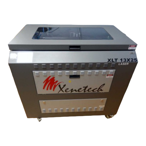
for all 13x25 & 24x36 Models
Pendant Cable Removal
Remove the lower front panel of your laser. If your model laser has fan panels attached to the door, be
sure to unplug them before setting the door to the side.
The control panel will be visible on the left side of the panel opening. At the front of the panel there is a
socket head screw that secures the panel to the laser. Using the allen wrench supplied in your toolkit,
remove the screw and set it to the side.
To remove the control panel, lift it straight up on the front as shown below. As you lift up, pull forward.
There is a hook that is built in to the base of the laser which hooks in to the rear of the control panel. By
Pulling forward as you lift up will slide the panel away from the hook.
As you lift and pull, gently slide the panel to the right. If you have cleared the hook then the panel will
slide freely. Once it moves free of the hook lower the panel and continue to slide it to the right until the
edge has cleared left opening of the laser as shown.
Lift up on the control panel and pull
forward to release it from the hook
Remove the socket
head screw that
secures the control
panel to the laser
Once released, gently move the control
panel to the right until it has cleared the
opening
Advertisement
Table of Contents

Related Manuals for Xenetech 13x25 Series

Summary of Contents for Xenetech 13x25 Series
- Page 1 Color Touchscreen Retrofit Instructions for all 13x25 & 24x36 Models Pendant Cable Removal Remove the lower front panel of your laser. If your model laser has fan panels attached to the door, be sure to unplug them before setting the door to the side. The control panel will be visible on the left side of the panel opening.
- Page 2 Once the control panel has cleared the edge of the opening, carefully swing the left side toward you as shown. This will give access to the panel without having to remove any more cables than necessary. Locate the tan colored pendant cable for the touchscreen. Loosen the two finger screws on the cable and carefully remove it from the control panel.
- Page 3 Touchscreen Removal Your current touchscreen is held in place using studs and locknuts. On the side of the touchscreen that is closest to the work light, you will see the two studs. Remove the locknuts from each of the two studs. This will allow you to remove the touchscreen and set it aside.
- Page 4 3. Center the touchscreen in the window of the sheet metal as shown. Doing so will line up the four necessary holes that you will use to secure the touchscreen to the sheet metal. 4. With the four holes lined up, use the included (4) 8- 32x5/8 button head screws to secure the touchscreen to the sheet metal.
- Page 5 4. Follow along the edge of the control board to the corner. Remove the corner screw and secure the ground strap as shown to the right. 5. The final connection is on the opposite corner of the control panel. Carefully move the controller as shown. Now locate the connector as shown below.
- Page 6 If your controller has two pins The plug on the touchscreen cable is a two pin plug as well as the connector on the controller. Plug the connector into the controller. The two are made so that they will only fit one way. Finishing Up 1.
Need help?
Do you have a question about the 13x25 Series and is the answer not in the manual?
Questions and answers