Table of Contents
Advertisement
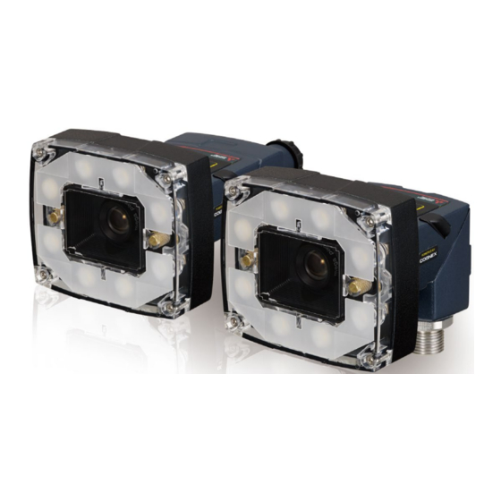
Vision Sensor Connection Guide
-VS20M-11F310
-VS20M-12F410
-VS20M-13F410
-VS20C-12F410
-VS20C-13F410
-VS70M-600-E
-VS70M-600-ER
-VS70M-600
-VS70M-600-R
-VS70M-800-E
-VS70M-800-ER
-VS70M-800
-VS70M-800-R
-VS70M-802-E
-VS70M-802-ER
-VS70M-802
-VS70M-802-R
-VS80M-100-E
-VS80M-100
-VS80M-200-E
-VS80M-200-ER
-VS80M-200
-VS80M-200-R
-VS80M-400-E
-VS80M-400-ER
-VS80M-400
-VS80M-400-R
This product is designed and manufactured by Cognex Corporation.
*Note that the warranty and general specifications of this product
differ from that of programmable controller products.
-VS80M-202-E
-VS80M-202-ER
-VS80M-202
-VS80M-202-R
-VS80M-402-E
-VS80M-402-ER
-VS80M-402
-VS80M-402-R
Advertisement
Table of Contents

Related Manuals for Mitsubishi Electric VS20M-11F310


Summary of Contents for Mitsubishi Electric VS20M-11F310
- Page 1 Vision Sensor Connection Guide -VS20M-11F310 -VS80M-202-E -VS20M-12F410 -VS80M-202-ER -VS20M-13F410 -VS80M-202 -VS20C-12F410 -VS80M-202-R -VS20C-13F410 -VS80M-402-E -VS70M-600-E -VS80M-402-ER -VS70M-600-ER -VS80M-402 -VS70M-600 -VS80M-402-R -VS70M-600-R -VS70M-800-E -VS70M-800-ER -VS70M-800 -VS70M-800-R -VS70M-802-E -VS70M-802-ER -VS70M-802 -VS70M-802-R -VS80M-100-E -VS80M-100 -VS80M-200-E -VS80M-200-ER -VS80M-200 -VS80M-200-R -VS80M-400-E -VS80M-400-ER -VS80M-400 -VS80M-400-R This product is designed and manufactured by Cognex Corporation.
-
Page 3: Safety Precautions
SAFETY PRECAUTIONS (Read these precautions before using this product.) Before using this product, please read this manual and the relevant manuals carefully and pay full attention to safety to handle the product correctly. The precautions given in this manual are concerned with this product only. For the safety precautions for other modules, refer to their respective user's manuals. - Page 4 [Startup and Maintenance Precautions] CAUTION ● Do not clean the Vision Sensor VS20 with highly irritating or corrosive solvent such as caustic alkali solution, methyl ethyl ketone (MEK), and gasoline. Doing so may cause a fault.
-
Page 5: Conditions Of Use For The Product
CONDITIONS OF USE FOR THE PRODUCT (1) This vision sensor shall be used in conditions; i) where any problem, fault or failure occurring in the vision sensor, if any, shall not lead to any major or serious accident; and ii) where the backup and fail-safe function are systematically or automatically provided outside of the vision sensor for the case of any problem, fault or failure occurring in the vision sensor. -
Page 6: Introduction
For details on how to register a profile, refer to the following manual. GX Works2 Version 1 Operating Manual (Common) GX Works3 Operating Manual For information on how to obtain a profile, please contact your local Mitsubishi Electric sales office or representative. -
Page 7: Table Of Contents
CONTENTS SAFETY PRECAUTIONS ..............1 CONDITIONS OF USE FOR THE PRODUCT . - Page 8 Setting a Programmable Controller ............78 Timing chart of an I/O connection .
-
Page 9: Chapter 1 Cc-Link Ie Field Network Basic Connection
CC-Link IE Field Network Basic CONNECTION This chapter explains the procedure for connecting a vision sensor VS20 to a programmable controller and controlling the vision sensor with CC-Link IE Field Network Basic connection. For details on CC-Link IE Field Network Basic, refer to the following manual. CC-Link IE Field Network Basic Reference Manual System Configuration Example for Connecting a Vision Sensor... -
Page 10: Configurations
Configurations The devices used in the system configuration are as follows. Required equipment ■Mitsubishi Electric products (1) Vision sensor (2) Programmable controller • VS20M-13F410 • CPU module: R08ENCPU (3) Engineering tool, profile (4) Vision sensor setup tool • GX Works3 •... -
Page 11: Connection And Wiring Of A Vision Sensor
Connection and wiring of a vision sensor This section shows the procedure for connecting and wiring a vision sensor. Operating procedure Check that the 24 VDC power supply is OFF. Connect an I/O or a serial wire to an appropriate device (such as a programmable controller). Connect the 24 VDC (red wire) and GND (black wire) of a breakout cable to the corresponding terminals on the power supply. -
Page 12: Basic Operations For A Cc-Link Ie Field Network Basic Connection
Basic Operations for a CC-Link IE Field Network Basic Connection Basic operation process for a CC-Link IE Field Network Basic connection With a CC-Link IE Field Network Basic connection, data communication (cyclic transmission) is periodically performed between a master station (programmable controller) and a slave station (vision sensor) using link devices. Remote input and output (RY and RX), and remote registers (RWr and RWw) are used for data communication. -
Page 13: Remote I/O Signals (Rx/Ry)
Remote I/O signals (RX/RY) The following shows the I/O signals for a master station (programmable controller) in a CC-Link IE Field Network Basic connection. The I/O signal assignment in the following tables is an example when the remote I/O signals of a vision sensor are assigned for RX0 to RX3F and RY0 to RY3F. - Page 14 For details on each data to control a vision sensor, refer to the help of In-Sight Explorer. Enter "CC-Link IE Field Network Basic" as a keyword in the [Search] tab of Help, and refer to the explanation of the data. 1 CC-Link IE Field Network Basic CONNECTION 1.2 Basic Operations for a CC-Link IE Field Network Basic Connection...
-
Page 15: Setting The Vision Sensor
Setting the Vision Sensor Start In-Sight Explorer to set the vision sensor. Setting an IP address to a personal computer Set the IP address (192.168.3.3) to a personal computer. Connecting the vision sensor Start In-Sight Explorer to set the vision sensor. Start In-Sight Explorer. - Page 16 Connect to the vision sensor. Click the [Connect] button to connect to the vision sensor. Ò 1 CC-Link IE Field Network Basic CONNECTION 1.3 Setting the Vision Sensor...
- Page 17 Creating a new job As an example, set a CE mark for inspection target. Create a new job. Click the [New Job] button. Ò Adjust so that the lens captures an inspection target in [Set Up Image], and configure the settings to acquire the image. ...
- Page 18 Set a tool. Click the [Locate Part] button. Select "Pattern". Click the [Add] button. Ò Ô Ó Set a model on the position to be detected. Set a model. (CE mark is selected.) Click the [OK] button. ...
- Page 19 Configuring a communication setting Configure the communication setting (CC-Link IE Field Network Basic). Click the [Communication] button. Click the [Add Device] button. Ò Ó Add the CC-Link IE Field Network Basic. Configure a device setting. • Device: PLC/Motion Controller •...
- Page 20 Add the data to be transmitted in the cyclic transmission of the CC-Link IE Field Network Basic. Select the [Format Output Word Data] tab. Click the [Add] button. Select the data to add in the following order. •...
- Page 21 Saving the job Name the created job. Click the [Save Job] button. Click the [Save As] button. Ò Ó Enter a file name and save the job. Enter an arbitrary file name. Click the [Save] button. Ò...
- Page 22 Set startup options for the vision sensor. Click the [...] button under "Job". Select the checkbox of "Load Job on Startup". Select the file name saved in step Select the checkbox of "Start the Sensor in Online Mode". ...
-
Page 23: Setting A Programmable Controller
Setting a Programmable Controller Set parameters of a programmable controller in GX Works3. Registering a profile Register the profile of a vision sensor in GX Works3. Profiles need to be registered when a GX Works3 project is closed. Start GX Works3. ... - Page 24 Setting a programmable controller Set parameters of a programmable controller in GX Works3. Create a new project in GX Works3. Select [New]. Ò Configure the settings in the "New" screen. Series: RCPU Type: R08EN Program Language: Ladder Ò...
- Page 25 Set the module parameter. Double-click [Module Parameter] in the "Navigation" window to set the module parameters. IP Address: 192.168.3.2 To Use or Not to Use CC-Link IEF Basic Setting: Enable Double-click the [Network Configuration Settings]. Ò Ó...
- Page 26 Configure the CC-Link IEF Basic configuration. Click the [Detect Now] button. • Read the message and click the [Yes] button. Ò • Check that the connected vision sensor is displayed. Click [Close with Reflecting the Setting]. For details on the automatic detection function of connected devices, refer to the following manual.
- Page 27 Configure the refresh settings. Double-click [Refresh Settings]. Set "Target", "Device Name", and "Start" on the CPU side. (Page 25 Refresh settings) Click the [Apply] button to end the parameter settings. Ò Ó Ô ■Refresh settings Link side CPU side Device name Target...
- Page 28 Creating a program Create a program using the devices set in the refresh settings. ■Devices used in the program Signal Signal name Description Remarks CC-Link IE Field Network Basic SM1536 Cyclic transmission status This signal turns ON when the cyclic transmission starts. Reference Manual SD1536.0 Cyclic transmission status for each...
-
Page 29: Timing Chart Of A Cc-Link Ie Field Network Basic Connection
Timing chart of a CC-Link IE Field Network Basic connection A timing chart when controlling a vision sensor using a programmable controller is shown below. To enable a trigger from a programmable controller, turn ON 'Trigger Enable' (RY0). When 'Trigger' (RY1) is turned ON while 'Trigger Ready' (RX0) is ON by turning ON 'Trigger Enable' (RY0), the status of the vision sensor is output to 'Trigger Ack' (RX1) and 'Inspection Completed' (RX9). -
Page 30: Writing The Parameters And Program
Writing the Parameters and Program Write the parameters and program set in GX Works3 to the programmable controller. Writing to the programmable controller Start the programmable controller. Click the [Write to PLC] button. Ò Write parameters. Click the [Parameter + Program] button. -
Page 31: Checking Operations
Checking Operations Check the operation by controlling the vision sensor using the programmable controller. Making the vision sensor online Make the vision sensor online and start the communication with the programmable controller. Check that the operating status is "Online". Ò... -
Page 32: Checking Inspection Results
Trigger a device. Turn "M1" ON to turn 'Trigger' (Y1001) ON. Ò Checking inspection results Check the inspection results. Check the completion of the inspection. Input "X1000" in "Device Name". Click the [Start Monitoring] button. Check that the bit of 'Inspection Ò... -
Page 33: Changing A Recognition Parameter
Changing a recognition parameter When locating a target object using the pattern in the location tool, the rotation tolerance of the target object can be changed to ±90°. Make the vision sensor offline with In-Sight Explorer. Add parameter items to the list in the [Format Input Word Data] tab. ... - Page 34 Set "Pattern_1.Rotation Tolerance" as a parameter to be changed. Set a device value in the "Device/Buffer Memory Batch Monitor" window in GX Works3. Enter 'W1000' for "Device Name". Click the [Start Monitoring] button. Enter '90' for 'User Data' (W1001) Ò...
-
Page 35: Changing Jobs (Loading Another Job)
Changing jobs (loading another job) The following shows the procedure to load the job file "1Test". The number '1' prefixed to the file name indicates an ID. By setting this ID number to 'Command' (W1000) of a remote resister (RWw), the job ("1Test") can be loaded. Set a device value in the "Device/Buffer Memory Batch Monitor"... -
Page 36: Chapter 2 Slmp Scanner Connection
SLMP SCANNER CONNECTION This chapter explains the procedure for connecting a vision sensor VS20 to a programmable controller and controlling the vision sensor with SLMP scanner connection. System Configuration Example for Connecting a Vision Sensor The following figure shows the system configuration for connecting a vision sensor VS20. (3) Engineering tool, Profile (4) Vision sensor setup tool (8) Ethernet cable... -
Page 37: Configurations
Configurations The devices used in the system configuration are as follows. Required equipment ■Mitsubishi Electric products (1) Vision sensor (2) Programmable controller • VS20M-13F410 • CPU module: R08ENCPU (3) Engineering tool, profile (4) Vision sensor setup tool • GX Works3 •... -
Page 38: Connection And Wiring Of A Vision Sensor
Connection and wiring of a vision sensor This section shows the procedure for connecting and wiring a vision sensor. Operating procedure Check that the 24 VDC power supply is OFF. Connect an I/O or a serial wire to an appropriate device (such as a programmable controller). Connect the 24 VDC (red wire) and GND (black wire) of a breakout cable to the corresponding terminals on the power supply. -
Page 39: Basic Operations For An Slmp Scanner Connection
Basic Operations for an SLMP Scanner Connection Basic operation process for an SLMP scanner connection Vision sensor Reading control area Reading CPU device Set poll interval Reading CPU device Reading control area Trigger ON Set the trigger instruction Bit of CPU device to ON with the PLC Reading control area Reading the control area using the vision... -
Page 40: Basic Operations For An Slmp Scanner Connection
Basic operations for an SLMP scanner connection In SLMP scanner connection, a vision sensor reads a control bit block from a programmable controller in the poll interval set with In-Sight Explorer, and processing according to the change of the bit information in the control bit block is performed. The status of the processing is written to the corresponding bit in the status bit block. -
Page 41: Data Blocks
Data blocks The following shows the details of six data blocks defined to control a vision sensor. • Control bit blocks Bit 7 Bit 6 Bit 5 Bit 4 Bit 3 Bit 2 Bit 1 Bit 0 Set Offline Reserved Execute Inspection Buffer Results... - Page 42 For details on the data block functions to control a vision sensor, refer to the help of In-Sight Explorer. Enter "SLMP scanner" as a keyword in the [Search] tab of Help, and refer to the explanation of the data block. 2 SLMP SCANNER CONNECTION 2.2 Basic Operations for an SLMP Scanner Connection...
-
Page 43: Setting The Vision Sensor
Setting the Vision Sensor Start In-Sight Explorer to set the vision sensor. Setting an IP address to a personal computer Set the IP address (192.168.3.3) to a personal computer. Connecting the vision sensor Start In-Sight Explorer to set the vision sensor. Start In-Sight Explorer. - Page 44 Connect to the vision sensor. Click the [Connect] button to connect to the vision sensor. Ò 2 SLMP SCANNER CONNECTION 2.3 Setting the Vision Sensor...
- Page 45 Creating a new job As an example, set a CE mark for inspection target. Create a new job. Click the [New Job] button. Ò Adjust so that the lens captures an inspection target in [Set Up Image], and configure the settings to acquire the image. ...
- Page 46 Set a tool. Click the [Locate Part] button. Select "Pattern". Click the [Add] button. Ò Ô Ó Set a model on the position to be detected. Set a model. (CE mark is selected.) Click the [OK] button. ...
- Page 47 Configuring a communication setting Configure the communication setting (SLMP scanner). Click the [Communication] button. Click the [Add Device] button. Ò Ó Add the SLMP scanner. Configure a device setting. • Device: PLC/Motion Controller • Manufacturer: Mitsubishi • Protocol: SLMP Scanner ...
- Page 48 Set the SLMP Scanner. Setting contents are as follows. • Controller Type: iQ-R/Q/L Series (3E Frame) • IP Address: 192.168.3.2 • Host Port: 12289 (Port number set for the Ethernet parameter in GX Works3) • Timeout (ms): 1000 • Poll interval (ms): 100 Ò...
- Page 49 Outputting to the programmable controller Set data to be output from the vision sensor to the programmable controller. As an example, set PASS, FAIL, and the number of inspection to the output word block (D1015 to D1017). Select the [Format Output Data] Ò...
- Page 50 Saving the job Name the created job. Click the [Save Job] button. Click the [Save As] button. Ò Ó Enter a file name and save the job. Enter an arbitrary file name. Click the [Save] button. Ò...
- Page 51 Set startup options for the vision sensor. Click the [...] button under "Job". Select the checkbox of "Load Job on Startup". Select the file name saved in step Select the checkbox of "Start the Sensor in Online Mode". ...
-
Page 52: Setting A Programmable Controller
Setting a Programmable Controller Set parameters of a programmable controller in GX Works3. Registering a profile Register the profile of a vision sensor in GX Works3. Profiles need to be registered when a GX Works3 project is closed. Start GX Works3. ... - Page 53 Setting a programmable controller Set parameters of a programmable controller in GX Works3. Create a new project in GX Works3. Select [New]. Ò Configure the settings in the "New" screen. Series: RCPU Type: R08EN Program Language: Ladder Ò...
- Page 54 Set the module parameter. Double-click "Module Parameter" in the "Navigation" window to set module parameters. IP Address: 192.168.3.2 Enable/Disable Online Change: Enable All (SLMP) Communication Data Code: Binary Double-click [External Device Configuration]. Ò Ó Ô Õ 2 SLMP SCANNER CONNECTION 2.4 Setting a Programmable Controller...
- Page 55 Set an Ethernet configuration. Click the [Detect Now] button. • Read the message and click the [Yes] button. • Check that the connected vision Ò sensor is displayed. Click [Close with Reflecting the Setting]. For details on the automatic detection function of connected devices, refer to the following manual.
- Page 56 Creating a program Create a program to control a vision sensor using the devices set in In-Sight Explorer. ■Devices used in the program Signal Signal name Description D1002.0 Trigger Ready The reception status of 'Trigger Enable' (D1000.0) is stored. • ON: Trigger is enabled. •...
-
Page 57: Timing Chart Of Slmp Scanner Connection
Timing chart of SLMP scanner connection A timing chart when controlling a vision sensor using a programmable controller is shown below. To enable the trigger from a programmable controller, turn ON 'Trigger Enable' of the control bit block. When 'Trigger' of the control bit block is turned ON while 'Trigger Ready' of the status bit block is ON by turning ON 'Trigger Enable', the status of the vision sensor is output to 'Trigger Ack' and 'Inspection Completed' of the status bit block. -
Page 58: Writing The Parameters And Program
Writing the Parameters and Program Write the parameters and program set in GX Works3 to the programmable controller. Writing to the programmable controller Start the programmable controller. Click the [Write to PLC] button. Ò Write parameters. Select the [Parameter + Program] button. -
Page 59: Checking Operations
Checking Operations Check the operation by controlling the vision sensor using the programmable controller. Making the vision sensor online Make the vision sensor online and start the communication with the programmable controller. Check that the operating status is "Online". Ò... -
Page 60: Enabling A Trigger On The Vision Sensor
Enabling a trigger on the vision sensor Enable a trigger on the vision sensor to acquire the inspection results. Open [Online] [Monitor] [Device/Buffer Memory Batch Monitor] in GX Works3 to display device values. Display device values. Enter "M0" for "Device Name". ... -
Page 61: Checking Inspection Results
Checking inspection results Check the inspection results. Check the completion of the inspection. Enter "D1000" for "Device Name". Click the [Start Monitoring] button. Check that the bit of 'Inspection Ò Ó Completed' (D1002.9) is changed (toggled). Ô Check the inspection results. -
Page 62: Changing A Recognition Parameter
Changing a recognition parameter When locating a target object using the pattern in the location tool, the rotation tolerance of the target object can be changed to ±90°. Make the vision sensor offline with In-Sight Explorer. Add parameter items to the list in the [Format Input Data] tab. ... - Page 63 Parameter items need to be added to the list in the [Format Input Data] tab in advance to change parameter values. More than one parameter item can be selected. Set the number of devices of "Input Block", depending on the number and size of parameters. When the number entered in "Number of devices"...
-
Page 64: Changing Jobs (Loading Another Job)
Changing jobs (loading another job) The following shows the procedure to load the job file "1Test". The number '1' prefixed to the file name indicates an ID. By setting this ID number to 'Command' (D2000) of an input word block, the job ("1Test") can be loaded. Set a device value in the "Device/Buffer Memory Batch Monitor"... -
Page 65: Controlling The Vision Sensor By Using Native Mode Commands
Controlling the vision sensor by using native mode commands The vision sensor can be controlled by using native mode commands. As an example, send the native mode command "GF (Get File)" to acquire the file name of the job in use. Setting the vision sensor Make the vision sensor offline with In-Sight Explorer. - Page 66 Check that the command and the command length are set correctly. Display device values in the "Device/Buffer Memory Batch Monitor" window in GX Works3. Enter 'D3000' for "Device Name". Click the [Start Monitoring] button. Check that the following information Ò...
- Page 67 For details on the native mode commands to control a vision sensor, refer to the help of In-Sight Explorer. Enter "Native Mode Commands" as a keyword in the [Search] tab of Help, and refer to the explanation of Native Mode Commands.
-
Page 68: Chapter 3 I/O Connection
I/O CONNECTION This chapter explains the procedure for connecting a vision sensor VS20 to a programmable controller and controlling the vision sensor with I/O connection. System Configuration Example for Connecting a Vision Sensor The following figure shows the system configuration for connecting a vision sensor VS20. (3) Engineering tool (4) Vision sensor setup tool (8) Ethernet cable... -
Page 69: Configurations
Configurations The devices used in the system configuration are as follows. Required equipment ■Mitsubishi Electric products (1) Vision sensor (2) Programmable controller • VS20M-13F410 • CPU module: R08ENCPU • Input module: RX40C7 • Output module: RY40NT5P (3) Engineering tool (4) Vision sensor setup tool •... -
Page 70: Connection And Wiring Of A Vision Sensor
Connection and wiring of a vision sensor This section shows the procedure for connecting and wiring a vision sensor. Ethernet cable connection Connect the Ethernet cable’s M12 connector to the vision sensor’s Ethernet connector. Connect the Ethernet cable’s RJ-45 connector to the switching hub or personal computer, as applicable. Connecting an I/O module (CIO-1400 I/O extension module) and an input/output module Check that the 24 VDC power supply is OFF. -
Page 71: Setting The Vision Sensor
Setting the Vision Sensor Start In-Sight Explorer to set the vision sensor. Setting an IP address to a personal computer Set the IP address (192.168.3.3) to a personal computer. Connecting the vision sensor Start In-Sight Explorer to set the vision sensor. Start In-Sight Explorer. - Page 72 Connect to the vision sensor. Click the [Connect] button to connect to the vision sensor. Ò 3 I/O CONNECTION 3.2 Setting the Vision Sensor...
- Page 73 Creating a new job As an example, set a CE mark for inspection target. Create a new job. Click the [New Job] button. Ò Adjust so that the lens captures an inspection target in [Set Up Image], and configure the settings to acquire the image. ...
- Page 74 Set a tool. Click the [Locate Part] button. Select "Pattern". Click the [Add] button. Ò Ô Ó 3 I/O CONNECTION 3.2 Setting the Vision Sensor...
- Page 75 Set a model on the position to be detected. Set a model. (CE mark is selected.) Click the [OK] button. Check that Name is "Pattern_1". Ò Ó Ô 3 I/O CONNECTION 3.2 Setting the Vision Sensor...
- Page 76 I/O settings Set inputs and outputs (I/O connection). Click the [Inputs/Outputs] button. Select "De-Energize While Offline". Click the [I/O Module] button. Ò Ó Ô Select an I/O module. Set "CIO-1400" in "Select I/O Ô Module". Ò ...
- Page 77 Set I/O signals. Set inputs and outputs. Click the [Details] button in the row of '3'. Ò Ò Ò Ó Setting I/O signals Input Signal Type Job Result Online/Offline Undefined Output Signal Type Job Result Direct 0 Job Result Pattern_1.Pass Direct 1 Job Result...
- Page 78 Saving the job Name the created job and save it. Click the [Save Job] button. Click the [Save As] button. Select the file name saved in "Startup Job" after saving the job. Ò Ó Enter a file name and save the job. ...
- Page 79 Set startup options for the vision sensor. Click the [...] button under "Job". Select the checkbox of "Load Job on Startup". Select the file name saved in step Select the checkbox of "Start the Sensor in Online Mode". ...
- Page 80 Setting a Programmable Controller Set parameters of a programmable controller in GX Works3. Setting a programmable controller Set parameters of a programmable controller in GX Works3. Start GX Works3. Start GX Works3 and create a new Ò project. Configure the settings in the "New" screen. ...
- Page 81 Set the system parameter. Double-click [System Parameter] in the "Navigation" window to set input/ output modules. Select [I/O Assignment]. Set "RX40C7" for slot 0 and "RY40NT5P" for slot 1. Click the [OK] button. Ò Ó Ô Õ...
- Page 82 Creating a program Create a program to control a vision sensor using I/O signals set in In-Sight Explorer. ■Devices used in the program Signal Signal name Description Remarks Pattern_1.Pass This signal turns ON when the inspection target set in When the vision sensor is not in the Pattern_1 is detected in the captured image.
- Page 83 ■Program example (11) (14) (0): Enable a trigger on the vision sensor. (2): Request the start of the image capture to the vision sensor. ('Trigger' (Y10) turns ON.) (7): "M0" turns ON when the inspection target set in Pattern_1 is detected in the captured image. (9): "M1"...
- Page 84 Writing the Parameters and Program Write the parameters and program set in GX Works3 to the programmable controller. Writing to the programmable controller Start the programmable controller. Click the [Write to PLC] button. Ò Write parameters. Click the [Parameter + Program] button.
- Page 85 Checking Operations Check the operation by controlling the vision sensor using the programmable controller. Making the vision sensor online Make the vision sensor online and start the communication with the programmable controller. Check that the operating status is "Online". Ò...
- Page 86 Trigger a device. Turn "M1" ON to turn 'Trigger' (Y10) Ò Checking inspection results Check the inspection results. Check the inspection results. Check the following information. • 'Pattern_1.Pass' (M10): This bit turns ON when the set inspection target is detected in the captured image.
-
Page 87: Using Cio-Micro I/O Module
Using CIO-MICRO I/O module An IP address needs to be set to use a CIO-MICRO I/O module. This section shows the procedure to set an IP address to a CIO-MICRO I/O module. For the vision sensors that can be connected to a CIO-MICRO I/O module, refer to the user's manuals of vision sensors. - Page 88 Set the network of the I/O module. Set items as follows. • IP Address: 192.168.3.4 • Subnet Mask: 255.255.255.0 Click the [OK] button. Ò Click the [OK] button. Ó Ô Select the I/O module. Select the checkbox of [De- Energize While Offline].
-
Page 89: Revisions
Japanese manual number: BCN-P5999-0860-D This manual confers no industrial property rights of any other kind, nor does it confer any patent licenses. Mitsubishi Electric Corporation cannot be held responsible for any problems involving industrial property rights which may occur as a result of using the contents noted in this manual. -
Page 90: Trademarks
TRADEMARKS The following are registered trademarks of Cognex Corporation: Cognex, 2DMAX, Advantage, AlignPlus, Assemblyplus, Check it with Checker, Checker, Cognex Vision for Industry, Cognex VSOC, CVL, DataMan, DisplayInspect, DVT, EasyBuilder, Hotbars, IDMax, In-Sight, Laser Killer, MVS-8000, OmniView, PatFind, PatFlex, PatInspect, PatMax, PatQuick, SensorView, SmartView, SmartAdvisor, SmartLearn, UltraLight, Vision Solutions, VisionPro, VisionView The following are trademarks of Cognex Corporation: The Cognex logo, 1DMax, 3D-Locate, 3DMax, BGAII, CheckPoint, Cognex VSoC, CVC-1000, FFD, iLearn, In-Sight (design... - Page 92 Cognex Corporation www.cognex.com BCN-P5999-0861-D(1903) HEAD OFFICE : TOKYO BUILDING, 2-7-3 MARUNOUCHI, CHIYODA-KU, TOKYO 100-8310, JAPAN NAGOYA WORKS : 1-14 , YADA-MINAMI 5-CHOME , HIGASHI-KU, NAGOYA , JAPAN When exported from Japan, this manual does not require application to the Ministry of Economy, Trade and Industry for service transaction permission. Specifications subject to change without notice.