
Related Manuals for Carel k.Air


Summary of Contents for Carel k.Air
- Page 1 Air handling unit controller USER MANUAL LEGGI E CONSERVA QUESTE ISTRUZIONI READ AND SAVE THESE INSTRUCTIONS k.Air +030220981 - ENG Up to date version available on www.carel.com...
- Page 3 The technical specifications shown in the manual may be changed innovations to products, procedures and strict quality processes without prior warning. The liability of CAREL in relation to its with in-circuit and functional testing on 100% of its products, and...
- Page 4 Warranty on materials: 2 years (from the production date, excluding consumables). Approval: the quality and safety of CAREL products are guaranteed by the ISO 9001 certified design and production system, as well as by the and marks Dangerous voltage. Caution, hot surface.
- Page 5 3.4 Power supply 9. FUNCTIONS 3.5 pGDE terminal connection 9.1 Dampers 3.6 Universal input/output connections 9.2 Activation Insulation type on k.Air mini and c.pCOe 9.3 Shutdown Insulation type on k.Air large 9.4 Types of control 9.5 PID control 4. USER INTERFACE 9.6 Temperature control...
- Page 6 12.2 Alarm parameters 12.3 Generic alarm input and output contacts. 12.4 Alarm table 13. SOFTWARE UPDATE 13.1 Update via USB cable 13.2 Update via USB pen drive 13.3 Update with file transfer via FTP 6 | k.Air +030220981 rel. 1.1 – 31.03.2020...
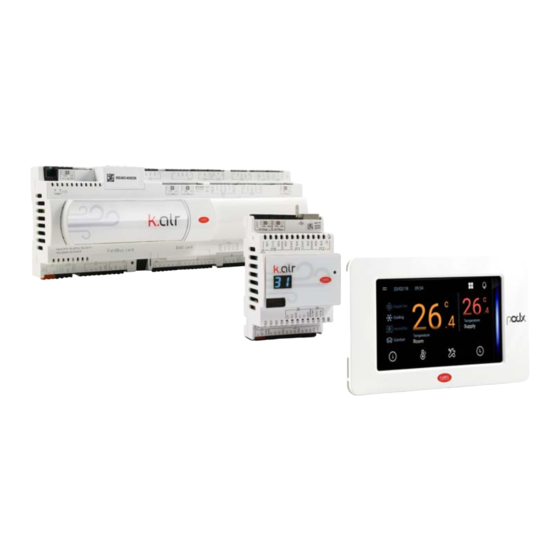
- Page 7 P/N P+DA00FHD*FK and large P/N P+5A00SFC*LK. Both models share the same software functions, however they differ in terms of the number and characteristics of the available inputs/outputs and serial communication ports.
-
Page 8: Main Features
(up to 6 devices); dehumidification by cooling coil (with dew point control) and reheating; control with 0- 10 V input for humidifier or Modbus connection for CAREL humiSonic and humifog humidifiers;... - Page 9 54 Auxiliary loop 3 input Main coil pump 2 55 Auxiliary loop 4 input Reheat coil pump 1 56 Heat recovery unit defrost Reheat coil pump 2 Filter alarm On/off heat recovery unit IEC humidifier Tab.1.a 1. Introduction | 9 k.Air +030220981 rel. 1.1 – 31.03.2020...
- Page 10 Fig.1.c Addr. Modbus Devices Supply fan Return fan 1 to 4 c.PCOe UChiller Power+ Humisonic 6 to 7 Humifog 128 to 137 Serial probe Th-Tune Tab.1.b 10 | 1. Introduction k.Air +030220981 rel. 1.1 – 31.03.2020...
-
Page 11: Duct Temperature Sensor
Fig.1.d Below is a list of devices that are suitable for use with k.Air. CAREL has passive and active temperature 1.3 Series of probes and differential pressure probes, for duct installation, designed specifically for heat recovery units accessories for and small air handling units. - Page 12 4 to 20 mA 0-3000 Pa 0-5000 Pa Tab.1.e Note: the k.Air mini +Vdc terminal provides a supply voltage of 12 Vdc ± 8%. If a higher voltage is required, use an external power supply. 12 | 1. Introduction k.Air +030220981 rel. 1.1 – 31.03.2020...
- Page 13 Range Output Range Output DCFL000100 1-9 m/s ON/OFF Tab.1.g Air quality sensor for rooms and ducts Fig.1.i SENSORS Range Output Range Output DPWQ402000 0-2000 ppm 0-10 V DPDQ402000 0-2000 ppm 0-10 V Tab.1.h 1. Introduction | 13 k.Air +030220981 rel. 1.1 – 31.03.2020...
- Page 14 The touch screen display guarantees simple human- machine interaction, making it easier to browse between the various screens. The pGDx terminal can be used to fully browse the k.Air webserver, thus acting as a unit terminal. In the version with built-in T/H probe, it can be used as a room terminal, getting the temperature and humidity values directly from the main controller.
- Page 15 In the Compact version, it has a capacity of 0.5 kg/h to 1 kg/h, and is designed to be built into compact units, such as heat recovery units, fan heaters, fan coils, etc. See manual +0300056EN. Fig.1.n 1. Introduction | 15 k.Air +030220981 rel. 1.1 – 31.03.2020...
- Page 16 Fig.1.o uChiller μChiller is Carel’s solution for the complete management of direct expansion units. The maximum configuration manages 2 compressors per circuit (On/Off or BLDC), up to a maximum of 2 circuits (using an expansion card for circuit 2). The distinctive element of μChiller is complete control of high-efficiency...
-
Page 17: Communication Ports
2. Communication ports See the c.pCO manual +0300057EN for the hardware characteristics of the serial ports. The k.Air controller manages the protocols on the serial ports shown in the table. Ref. Type/connectors Model Specifications Protocol Integrated on main board pLAN... - Page 18 Fig.2.a Fig.2.b 18 | 2. Communication ports k.Air +030220981 rel. 1.1 – 31.03.2020...
-
Page 19: Hardware Installation
3. Hardware installation 3.1 Assembly The k.Air controllers are available in the DIN rail mounting version. See the technical documentation +0300057EN. The th- Tune terminal is available in the flush- mounted and wall- mounted versions. For and dimensions assembly, see the technical leaflets +0500016IE, +0500017IE. - Page 20 Fig.3.d pGDX Fig.3.e 20 | 3. Hardware installation k.Air +030220981 rel. 1.1 – 31.03.2020...
- Page 21 LED and red +VDC overload LED VG: power at voltage A (*) for opto-isolated analogue output VG0: power for opto-isolated analogue output, 0 Vac/Vdc Analogue outputs 3. Hardware installation | 21 k.Air +030220981 rel. 1.1 – 31.03.2020...
-
Page 22: 3. Hardware Installation
(contactors, circuit breakers and the like) to avoid possible electromagnetic disturbance; 22 | 3. Hardware installation k.Air +030220981 rel. 1.1 – 31.03.2020... -
Page 23: Electrical Installation
90 degrees, always avoiding running the controller cables parallel to the power cables; reduce the path of probe cables as much as possible, and avoid spiral paths that enclose power devices; in the event of any malfunctions, do not attempt to repair the device, rather contact a CAREL service centre. Electrical installation Important: before carrying out any maintenance, disconnect the controller from the power supply by moving the main system switch to “off”. -
Page 24: Power Supply
Use the accessory cable P/N S90CONN0S0, as shown in the figure. The maximum distance allowed between controller and terminal is 10 m. pGDE terminal Note: for connection cable lengths > 10 m or to connect multiple terminals, use the TCONN6J000 connection accessory. See manual +0300057EN. Fig.3.i 24 | 3. Hardware installation k.Air +030220981 rel. 1.1 – 31.03.2020... -
Page 25: Universal Inputs/Outputs
Note: the table indicates the maximum number of inputs that can be connected. For example, with k.Air mini, a maximum of two 4- 20 mA inputs from probes powered by the controller and a maximum of four 4-20 mA inputs probes powered externally can be connected. The maximum total number of inputs of both types is however four. - Page 26 For the operating range, see the technical specifications table in manual +0300057EN. Fig.3.k Controller terminals NTC probe Wire 1 Wire 2 Wire 1 Wire 2 Wire 1 Wire 2 Wire 1 Wire 2 Tab.3.d 26 | 3. Hardware installation k.Air +030220981 rel. 1.1 – 31.03.2020...
- Page 27 For the operating range, see the probe data sheets. The controller can be connected to all CAREL DP* series active temperature and humidity probes configured with 4-20 mA signal. Note: the k.Air mini models do not accept 0-10 Vdc signals as inputs from probes powered by the controller. Fig.3.l...
- Page 28 Connection of active probes with 0-10 V output powered externally See the table at the beginning of the paragraph for the maximum number of probes that can be connected. For the operating range, see the probe data sheets. Fig.3.n 28 | 3. Hardware installation k.Air +030220981 rel. 1.1 – 31.03.2020...
- Page 29 Tab.3.i Maximum number of analogue outputs that can be connected Analogue outputs (not opto-isolated) k.Air mini k.Air large c.pCOe 0-10 Vdc (class 2) (maximum current 2 mA) max 5 max 5 Tab.3.j 3. Hardware installation | 29 k.Air +030220981 rel. 1.1 – 31.03.2020...
- Page 30 Vterm k.Air large: 24 Vdc ± 10% - To be used to power an external terminal as an alternative to the one connected to J10, Pmax = 1.5 W. Max connection cable length: 30 m; if the length exceeds 10 m, use a shielded cable with the shield connected to earth.
-
Page 31: Digital Inputs
3.6.2 Digital inputs The controller features digital inputs for monitoring safety devices, alarms, device states and remote enabling signals. See manual +0300057EN. Maximum connection cable length: k.Air mini 10 m, k.Air large 30 m. Important: the k.Air controller does not provide any protection, limitation or functional safety for the controlled devices. -
Page 32: Connection Of Digital Inputs
Connection of digital inputs There are no specific constraints on the maximum number of inputs that can be connected. For the k.Air mini controller, see the figure above, while for k.Air large, a possible connection example is shown below. See manual +0300057EN. -
Page 33: Digital Outputs
Tab.3.q The following tables apply in relation to the type of insulation. Insulation type on k.Air mini and c.pCOe Between relays in group 1 (R1, R2) and 2 (R3, R4, R5) basic Between relays in group 3 (R6) and relays in group... -
Page 34: Connection Of Digital Outputs
Important: the current running through the common terminals must not exceed the rated current of a single terminal: k.air mini: 5 A for groups 1 and 2, 1 A for group 3; k.Air large: 8 A Remote control of digital outputs The cable sizes based on the current are shown in the following table. -
Page 35: Connection Diagrams
For details on mounting the c.pCOe expansion cards, see technical leaflet +0500059IE. The k.Air controller is designed to be able to host up to four c.pCOe cards with serial addresses from 2 to 5; to assign the serial address to the c.pCOe card, the dipswitches on the card must be set as shown in the figure;... -
Page 36: User Interface
4. User interface 4.1 Introduction The k.Air system uses the user terminal (P/N PGNE000*) for displaying alarms and some key values, and for setting the parameters. The terminal comprises a display and 6- button keypad for configuring and programming the unit. The main information can also be displayed on the pGDX graphic terminal. - Page 37 31 LOW SUPPLY T Minimum supply limit control 32 HIGH SUPPLY T Maximum supply limit control 33 HIGH H SAT High humidity control (VDI) 34 START INACT. Start due to inactivity (VDI) Tab.4.b 4. User interface | 37 k.Air +030220981 rel. 1.1 – 31.03.2020...
-
Page 38: Programming Mode
Example: screen Ac01 is the first screen in menu A. Unit →c. Configuration. 38 | 4. User interface k.Air +030220981 rel. 1.1 – 31.03.2020... -
Page 39: Setting The Parameters
1. Press Esc one or more times to go to the standard display; 2. Press Prg: after entering the user password, the main menu is shown; 3. Press UP/DOWN and select category X: Settings; press Enter to confirm; 4. User interface | 39 k.Air +030220981 rel. 1.1 – 31.03.2020... -
Page 40: Quick Access Menu
The quick access menu screens are identified by an alphanumeric code at the top right, the first letter Q indicates the quick access menu, the second lowercase letter indicates the submenu branch: a. Info, b. On/Off, c. Set point; finally, the number identifies the screen in the menu. 40 | 4. User interface k.Air +030220981 rel. 1.1 – 31.03.2020... - Page 41 Damper status based on opening time Outside air, mixing and exhaust damper status Bypass damper status and request, unit status. Air quality probe measurement and set point. Request and % activation of the supply/return fans 4. User interface | 41 k.Air +030220981 rel. 1.1 – 31.03.2020...
- Page 42 Scheduler active from c.pCO controller or from th- Tune room terminal. Scheduler active: daily programming, holiday program or special days. The next two screens show information on the software version and operating system, the size of the k.Air controller and the cycle time.
- Page 43 Comfort, Economy, etc.) and/or unit is switched off. In this case, the reference set points will depend on the profile and will be shown on the screens in menu Aa. Also see the chapter on the Scheduler. 4. User interface | 43 k.Air +030220981 rel. 1.1 – 31.03.2020...
- Page 44 Note: see technical leaflets +0500016IE/+ 0500017IE for assembly of the terminal. Once connected to the k.Air controller and enabled, th- Tune allows the user to control the room temperature and relative humidity (NOTE: the room humidity set point can however only be set on the pGDE terminal) and change some settings, such as operating mode and time bands.
- Page 45 5.3 Display During normal operation, the display shows, in addition to the current day of the week and time, the status of the fans, the room probe measurement and the operating mode. 5. th-Tune (accessory) | 45 k.Air +030220981 rel. 1.1 – 31.03.2020...
- Page 46 OFF from digital input OFF by FAN OFF due to fan alarm OFF by COND OFF due to alarm during start-up STRT UP Unit starting SHUT DOWN Shutting down OPERATING MODE ICON Cooling Heating Automatic 46 | 5. th-Tune (accessory) k.Air +030220981 rel. 1.1 – 31.03.2020...
-
Page 47: Setting The Time And Day Of The Week
See the paragraph at the end of the chapter. The time bands set on the th- Tune terminal are only effective when the k.Air controller is in Comfort mode. In Economy mode, the unit set point depends on Setting the time the set point configured on the corresponding screen on the controller. - Page 48 Tab.5.f The resulting room temperature set point is shown in the figure, where it can be seen that the th-Tune set point is only considered when the pGDE is in “Comfort” mode. 48 | 5. th-Tune (accessory) k.Air +030220981 rel. 1.1 – 31.03.2020...
- Page 49 Press the knob 1 to 4 times to display the temperature/humidity values: Main data 1. room temperature set point, display 2. relative humidity reading; 3. supply probe reading; 4. outside probe reading. 5. th-Tune (accessory) | 49 k.Air +030220981 rel. 1.1 – 31.03.2020...
- Page 50 Main scheduler on k.air point th-Tune scheduler (active only if the k.air scheduler is not active or it is in Comfort mode) Change set point using the control knob. The control knob can always be used to change the main control set point (temperature). This set point will then be permanently active if no scheduler is active, or temporary if one or both schedulers are active.
-
Page 51: Fan Speed Control
(*) manual: manual mode, see chap. “Commissioning” and parameters in group Ad. Automatic: normal operating mode 5.10 Procedure for setting the time bands on th-Tune To set the time bands, the unit must be ON. Procedure: 5. th-Tune (accessory) | 51 k.Air +030220981 rel. 1.1 – 31.03.2020... - Page 52 7. Press the knob: the display flashes on the start 8. Turn the knob and set the hours 9. Press the knob: the display flashes on the start hours for the first time band minutes for the first time band. 52 | 5. th-Tune (accessory) k.Air +030220981 rel. 1.1 – 31.03.2020...
- Page 53 16. Press the knob (ESC) or the Power button one or more times to go back to the standard display. Press Clock to activate the time bands (the home icon is displayed). 5. th-Tune (accessory) | 53 k.Air +030220981 rel. 1.1 – 31.03.2020...
- Page 54 MAC Address. Fig.6.b Network connection of the pGDx terminals and k.air Procedure 1. connect the pGDx terminal to the power supply and the Ethernet cable. See technical leaflet +050001895;...
- Page 55 If needing to use the temperature and humidity probes included in the pGDx terminal: go to screen Y065 and enter the last 4 digits of the MAC Address. In this way, k.air will acquire the values read by the temperature and humidity probe, which can be assigned as a room temperature and humidity probe for the space where the terminal is located.
- Page 56 DNS (xxx.xxx.xxx.XXX) IR565 PIV3879 The main programming menu provides access to all of the k.Air controller parameters, also using the function that simulates the user terminal, available by selecting “Service”. Note: when simulating the user terminal, the k.Air controller user menu can also be accessed. For further details, see the c.pCO manual +0300057EN.
-
Page 57: Menu Description
→ F. Humidifiers G. Filters H. Auxiliary control I. IEC J. VDI T. Alarm logger a. View b. Export U. Compressor a. Configuration b. BLDC c. Power+ V. EXV W. In/Out 7. Menu description | 57 k.Air +030220981 rel. 1.1 – 31.03.2020... -
Page 58: Service Parameters
Note: parameters Bb07 to Bb22 refer to the ebm-papst EC fan (fan type = Modbus). a. Return fan. See Bb. Note: parameters Bc07 to Bc22 refer to the ebm-papst EC fan (fan type = Modbus). 58 | 7. Menu description k.Air +030220981 rel. 1.1 – 31.03.2020... - Page 59 Heat recovery unit: PID parameters, activation thresholds, defrost parameters; Modulating bypass damper: minimum and maximum limits, operating hours; 7. F Humidifier: type (modulating or CAREL humiSonic controlled via serial), set operating hours before alarm; Enable humidification control, PID parameters; Humidifier operating times: time between washing cycles, read variables;...
-
Page 60: Manufacturer Parameters
K; select the type of fans, heating device (heater/water coil) and the type (ON/OFF, modulating); select the type of heat exchanger (plate/rotary), outside air damper and bypass damper; select the type of humidifier (modulating/humiSonic/Humifog); 60 | 7. Menu description k.Air +030220981 rel. 1.1 – 31.03.2020... - Page 61 Note: k.Air is factory set for correct display on a pGDE terminal with address 32 in the pLAN network (default); for more details on using the terminal, see manual +0300057EN.
-
Page 62: Manual Configuration
+3000204. All k.Air models are equipped with a USB or micro USB host (Master) port that a USB mass storage device can be plugged into (typically a USB pen drive or portable hard disk) so as to load a custom Upload configuration. -
Page 63: Input/Output Configuration
For each device, sensor or contact (referred to as “points”), an acquisition channel needs to be selected from those available on the main board or expansions. Input/output Menu W.In/Out is used to configure and check the inputs and outputs connected to the k.air controller. configuration There are four configuration screens:... -
Page 64: Unit Of Measure
Note: the minimum and maximum conversion values rescale the output signal. Specifically, the minimum value is also active when the unit is OFF. The k.Air controller is configured to display International System units of measure. Access screen Wc01 to 8.6 Unit of set a different unit of measure, if desired. - Page 65 Reheating coil pump 2 Ae75 Reheating coil (modulating) Ae78 Reheating coil heater 1 Ae81 Reheating coil heater 2 Ae83 Reheating coil heater 3 Ae84 Reheating coil heater 4 Ae99 Reset all counters Tab.8.d 8. Commissioning | 65 k.Air +030220981 rel. 1.1 – 31.03.2020...
-
Page 66: Manual Mode
The k.Air software manages the devices that communicate via the FieldBus (mini model) or Fieldbus2 (large model) serial network using the Modbus protocol, with the following frame: FieldBus serial baud rate: 19200; port parity: none; configuration stop bits: 2. The device addresses must be set as shown in the table: Addr. - Page 67 Important: when loading a configuration, all of the parameters are set to the value saved in the file, and therefore any subsequent changes will be lost. Important: unplug any USB cables connected to the USB device port (k.Air large) before loading a configuration.
-
Page 68: Load Configuration
1. connect a USB pen drive with micro USB connector; 2. access screen Ac99; 3. select “Import”, “USB”; 4. type in the exact file name and confirm; 5. a confirmation message is shown to indicate that the operation was successful. 68 | 8. Commissioning k.Air +030220981 rel. 1.1 – 31.03.2020... - Page 69 9. Functions 9.1 Dampers k.air manages up to six types of dampers, on/off or modulating, with the following specific control functions: Damper Relationship Control Air quality Fresh air Unit activation and main control functions Frost protection Exhaust Temperature control Mixing...
- Page 70 Air Quality - Damper PID parameters - Integral R/W HR1641 PIV3136 time Fresh air damper - Minimum control value 0.0 100.0 % R/W HR1642 AV3137 Ca06 Fresh air damper - Maximum control value 100.0 0.0 100.0 % R/W HR1643 AV3138 70 | 9. Functions k.Air +030220981 rel. 1.1 – 31.03.2020...
-
Page 71: Bypass Damper
Note: when the unit is Off, the bypass damper will be open. The k.air software enables the unit to be switched on only if all of the enabled commands are set to ON 9.2 Activation (from pGDE/thTune, BMS, digital input, scheduler). When the unit is switched on, a procedure is activated to verify all of the safety conditions and activate the devices following a certain sequence;... - Page 72 On start-up, the fresh air, exhaust and bypass dampers are opened completely. The next phase starts after a delay (opening time - “Ca01") to allow complete opening. If the return fan is fitted, this is started, and 72 | 9. Functions k.Air +030220981 rel. 1.1 – 31.03.2020...
- Page 73 PIV3134 Shutdown In the same way as when switching on, the k.Air software enables the unit to be switched off if at least one of the enabled commands is set to OFF (PGD1/th-Tune, BMS, DI, Scheduler). Once the command is received, the unit goes into shutdown status, during which the devices follow a specific sequence until the unit is completely switched OFF.
- Page 74 Fig.9.e 74 | 9. Functions k.Air +030220981 rel. 1.1 – 31.03.2020...
- Page 75 Fig.9.f 9. Functions | 75 k.Air +030220981 rel. 1.1 – 31.03.2020...
-
Page 76: Types Of Control
1. humidity: the humidity request is sent by the controller to a humidifier via the 0-10 V output or via the Modbus serial port (CAREL humiSonic, Carel Humifog); 2. dehumidification: the controller sends the request, either directly or via the dew point calculation, to the main coil. - Page 77 9.5.2 Sequential PID The k.Air controller has different functions and devices that can act alone or in a coordinated way to ensure the best indoor comfort conditions. Each of these devices may either be present or absent, or enabled or disabled on the unit; therefore, depending on the situation, it will have a different impact on energy consumption during operation.
- Page 78 Diff_1. Fig.9.k Request Request Reg_var Control variable Offset Set point Diff_1/2 Differential 1/2 78 | 9. Functions k.Air +030220981 rel. 1.1 – 31.03.2020...
- Page 79 9.5.3 Incremental PID Incremental PID is the most common control mode on k.air. It is used for a single point control and is based on a PID controller designed to avoid variations in the output in the event of variations to the set point.
- Page 80 When the signal moves outside of the dead band, the output is increased, or decreased, without sudden variations. Fig.9.m Request Alarm Alarm Set point diff Differential Dead band Control probe 80 | 9. Functions k.Air +030220981 rel. 1.1 – 31.03.2020...
-
Page 81: Temperature Control
The PID parameters relating to cascade control, used to calculate the supply set point The minimum and maximum supply limits, used as the control range for calculating the supply set point Room or return set point 9. Functions | 81 k.Air +030220981 rel. 1.1 – 31.03.2020... - Page 82 For adiabatic humidification, the production of humidity is also limited as the last stage of the low supply temperature limit function. This accessory function is also active, as the only limit stage, in the main supply temperature control function. Below is a summary of the limit action. 82 | 9. Functions k.Air +030220981 rel. 1.1 – 31.03.2020...
-
Page 83: Cooling And Heating
Low supply temp: integral time 120 0 R/W HR1361 PIV2869 The k.Air controller is extremely flexible in adapting to the temperature control demands and characteristics of the system so as to respond to changes in season or over a day. Cooling and... - Page 84 Cooling/heating unit type enabled DI700 BV1158 Unit cooling/heating mode configuration R/W HR1311 PIV2819 Cooling outside temperature threshold 28.0 99.9 °C R/W HR1312 AV2820 99.9 Ac24 Heating outside temperature threshold 18.0 99.9 °C R/W HR1313 AV2821 99.9 84 | 9. Functions k.Air +030220981 rel. 1.1 – 31.03.2020...
- Page 85 Heating: outside temperature compensation 0.0 -50.0 90.0 °C R/W HR1182 AV2692 threshold Heating: outside temperature compensation delta -8.0 -30.0 30.0 °C R/W HR1183 AV2693 Aa90 Heating: maximum compensation offset -2.0 -20.0 10.0 °C R/W HR1184 AV2694 9. Functions | 85 k.Air +030220981 rel. 1.1 – 31.03.2020...
- Page 86 9.9 Coils k.air can manage up to three coils, called preheating, main and reheating. Each of these has different characteristics and requirements. The table below summarises the main features, while the details are described in the chapters corresponding to each control function.
- Page 87 A further option available is control of the coil supply water temperature. k.air activates an alarm on exceeding a high or low temperature threshold, after a settable delay. An action can be set in response to the alarm, selected from the following:...
- Page 88 Each load connected to the digital outputs must have twice the power as the previous one. The table and image below show the activation sequence with two outputs and three steps. Request Digital output 1 Digital output 2 100% Fig.9.r 88 | 9. Functions k.Air +030220981 rel. 1.1 – 31.03.2020...
- Page 89 Direct expansion coil with integrated management This configuration, available only on k.air mini, involves the installation of a refrigerant circuit using the inputs/outputs, unipolar expansion valve and communication with the Power+ inverter on the controller, so as to integrate direct expansion architecture with high efficiency.
-
Page 90: Compressor Management
R/W HR1914 PIV3940 9.10.1 Compressor management 9.10 Direct expansion k.air manages ON/OFF compressors with direct starting or modulating BLDC compressors. For BLDC with integrated compressors, more than 200 models can be selected. A BLDC compressor is always driven by a Power+ management... - Page 91 MOP and DeltaP minimum ExV opening management parameters set point control parameters (BLDC only) alarm prevention parameters Note: to view the graphs of BLDC compressor envelopes, see the CAREL document “BLDC compressor envelopes”, available on ksa.carel.com 9.10.4 BLDC compressor start-up procedure k.air manages the start-up of BLDC compressors in accordance with the manufacturer’s specifications: on...
- Page 92 A high compression ratio is a thermal limit of compressor operation: normally control is activated at the limit of the envelope, reducing capacity when the limit is exceeded; if a probe is fitted to measure discharge temperature and if the temperature approaches the limits, as the critical condition involves 92 | 9. Functions k.Air +030220981 rel. 1.1 – 31.03.2020...
- Page 93 1. Decrease the rate of capacity increase. BLDC compressor 2. Increase capacity Variable MOP Low differential pressure prevention (zone 7) Device Description 1. Decrease the rate of capacity increase. BLDC compressor 2. Increase capacity Variable MOP 9. Functions | 93 k.Air +030220981 rel. 1.1 – 31.03.2020...
-
Page 94: Compressor Shutdown
Compressor delay at start-up/in operation Compressor start-up is a critical phase and for this reason k.air has differentiated control for some alarms to exceed the transient phase from compressor start- up and allow it to reach steady operation. The... - Page 95 Carel’s Power+ and ExV system. uChiller can be easily integrated with k.air via the managed by Fieldbus serial port to develop air handling units with a direct expansion main coil. k.air sends the start- up and capacity modulation commands, making available the main operating status information directly uChiller on the pGDE display, such as active compressors and active faults.
- Page 96 Evaporation pressure Suction temperature Close contact Compressor 1 thermal protector High pressure switch Compressor 2 thermal protector Remote alarm (close contact if not used) Compressor 1 Compressor 2 Reversing valve Alarm Condenser fan 96 | 9. Functions k.Air +030220981 rel. 1.1 – 31.03.2020...
- Page 97 4. Using the Applica or uChiller display app, configure the parameters relating to the refrigeration unit. 5. Set parameter Hd00 (supervisor address) to 10. 6. On the k.air pGDE terminal, enable the main coil as uChiller on screen Ac08, and set the operating mode on Da01.
- Page 98 For example, if set to 30%, it means when the fresh air damper is fully closed, IEC is limited by 30%. By default the parameter is set to 0%, i.e. the limit is disabled. 98 | 9. Functions k.Air +030220981 rel. 1.1 – 31.03.2020...
-
Page 99: Humidity Control
Control can be performed using the relative humidity value or the absolute humidity value. To assist commissioning, the set point will still be the relative humidity value, and k.air will then calculate the equivalent in absolute humidity by taking into account the temperature set point; the result is shown on the info screen. - Page 100 Humidification/Dehumidification: Control 20.0 99.0 %rh R/W HR1321 AV2829 band Ac36 Humidification/Dehumidification: Control min R/W HR1322 PIV2830 change delay time Note: absolute humidity control, once enabled, applies to both dehumidification and humidification 100 | 9. Functions k.Air +030220981 rel. 1.1 – 31.03.2020...
- Page 101 Humidifier output reduction second stage. Humidifier output reduction The heating devices are controlled to keep the supply Supply temp. control Humidifier output reduction temperature constant, if sufficiently sized, humidifier output is not reduced. 9. Functions | 101 k.Air +030220981 rel. 1.1 – 31.03.2020...
- Page 102 BV253 reset request Note: if CAREL humiSonic or Humifog humidifiers are used, the humidifier must be configured according to the commissioning procedure, as described in the specific manuals or technical leaflets. Dehumidification is controlled by a main cooling or mixed coil, when appropriately enabled (Ac04).
- Page 103 Note: for both control functions, dehumidification mode acts on the cooling coil only when the unit is in dehumidification status. This status is activated when the humidity control request is greater than 20%. Dehumidification status is visible in the unit status information on the main screen. 9. Functions | 103 k.Air +030220981 rel. 1.1 – 31.03.2020...
-
Page 104: Activation Conditions
Note: the following graphs assume a fixed outside temperature. FREECOOLING (cooling request active) Fig.9.ad ON: RetT- ExtT> delta_fc; OFF: RetT-ExtT<0 FREEHEATING (heating request active) Fig.9.ae ON: ExtT-RetT> delta_fh; OFF: ExtT-RetT<0 104 | 9. Functions k.Air +030220981 rel. 1.1 – 31.03.2020... -
Page 105: Heat Recovery
The heat recovery unit, if enabled on Ac01, is always available as a control stage in the main sequential temperature control PID. However, the freecooling/freeheating conditions must not be true at the same time, as these are mutually exclusive. k.air can manage the following types of heat recovery unit: Type Signal/actuator Control... - Page 106 Maximum defrost heat exchanger duration 999 min R/W HR1466 PIV2973 E016 Exhaust temperature threshold for defrost 20.0 90.0 °C R/W HR1468 AV2974 50.0 Stratification correction factor of the room E020 0.0 10.0 R/W HR1469 AV2975 temperature 106 | 9. Functions k.Air +030220981 rel. 1.1 – 31.03.2020...
- Page 107 9.18 k.air manages up to two fans, one for supply and one for return, which may be: On/off. Fans Modulating. 3-speed modulating; Modulating via Modbus (EBMPapst); The return fan is optional, and if enabled it will be the same type as the supply fan. The configuration is available on screen Ac01 and subsequently in menu B.Fans.
- Page 108 The fan speed is automatically modulated based on the differential pressure/air flow-rate set points. The PI control parameters are the same for both. The differential pressure sensor is used in both pressure and flow-rate mode; the conversion between the values depends on the coefficient K. Fig.9.af 108 | 9. Functions k.Air +030220981 rel. 1.1 – 31.03.2020...
- Page 109 R/W HR1899 AV3379 9.18.2 Flow and thermal overload alarm On k.air the following digital contacts can be enabled to check correct functioning of the fans Supply fan thermal protector, total unit shutdown Return fan thermal protector, fans stopped Fan thermal protector, total unit shutdown. The thermal protectors for the two fans must be...
- Page 110 Priority between minimum ventilation and night Ba21 freecooling (FALSE: minimum ventilation; TRUE: FALSE 0 R/W CS249 BV249 freecooling) 9.18.5 Filters k.air can manage the following filters: Supply filter 1 alarm Supply filter 2 alarm 110 | 9. Functions k.Air +030220981 rel. 1.1 – 31.03.2020...
- Page 111 Tab.9.i 9. Functions | 111 k.Air +030220981 rel. 1.1 – 31.03.2020...
- Page 112 5. If the fan with flow-rate or pressure control is enabled, set the maximum air quality limit in m3/h or Pa 6. Set the air quality set point in the set point menu. 112 | 9. Functions k.Air +030220981 rel. 1.1 – 31.03.2020...
-
Page 113: Auxiliary Control
“enable quick menu”. This allows the set point to be defined by the end user with unprotected access. 9. Functions | 113 k.Air +030220981 rel. 1.1 – 31.03.2020... - Page 114 The On/Off heater features “direct- heating” activation, with the trend shown in the figure, while for the modulating heater, the action depends on the PID parameters. 114 | 9. Functions k.Air +030220981 rel. 1.1 – 31.03.2020...
-
Page 115: Frost Protection
“Frost Off” status, if enabled. Deactivation Frost protection is deactivated when the frost protection thermostat switches or the value read by the frost protection probe is greater than the frost protection threshold plus a settable differential. 9. Functions | 115 k.Air +030220981 rel. 1.1 – 31.03.2020... - Page 116 Supply probe threshold Fig.9.al Control If the condition for ending frost protection does not occur before the “Warning delay” time, the unit goes into frost protection status and the corresponding procedure is started. 116 | 9. Functions k.Air +030220981 rel. 1.1 – 31.03.2020...
-
Page 117: Frost Prevention
Frost protection heater request P_vent_T Post-ventilation time Al_delay Alarm delay time Ext/Exh_ Fresh air/exhaust damper damp Min_lim Fresh air damper min limit Min_sp Minimum fan speed Frost protection warning delay Low_s_thr Low temperature threshold Fig.9.am 9. Functions | 117 k.Air +030220981 rel. 1.1 – 31.03.2020... - Page 118 HEAT EXCHANGE Bypass damper closed Thermal wheel at maximum speed The controller therefore opens the bypass damper and adjusts the speed of the thermal wheel using the same modulating output, to prevent defrosting. 118 | 9. Functions k.Air +030220981 rel. 1.1 – 31.03.2020...
- Page 119 9.22.2 Thermal wheel To prevent activation of frost protection, the thermal wheel, starting from the minimum bypass damper opening threshold, decreases speed until stopping, reducing heat exchange between exhaust air (warm) and fresh air (cool). 9. Functions | 119 k.Air +030220981 rel. 1.1 – 31.03.2020...
- Page 120 Note: when the outside temperature is very low, and the minimum time has elapsed between successive defrosts, defrosting starts again. Fig.9.ap Exh_T Exhaust temperature Ext_T Outside temperature Byp_Damp_Max_Op_thr Start defrost threshold Exh_T_thr End defrost threshold 120 | 9. Functions k.Air +030220981 rel. 1.1 – 31.03.2020...
- Page 121 3. evaporation temperature (conversion from suction pressure) < start defrost threshold During defrosting, the fans operate at the speed set for “Defrost fan request”. End defrost conditions The unit ends the defrosting procedure if one of these conditions occurs: 9. Functions | 121 k.Air +030220981 rel. 1.1 – 31.03.2020...
- Page 122 (end defrost threshold not reached). The time between defrosts is needed to prevent the unit from defrosting too frequently and thus only partly meeting demand. 122 | 9. Functions k.Air +030220981 rel. 1.1 – 31.03.2020...
- Page 123 Evaporation temperature delta On/off compressor D_b_cycle_rev Delay before reversing cycle CMP_BLDC BLDC compressor Defrost by reversing the cycle Post-dripping Cmp_off_t Compressor OFF time Def_reg Defrost request time Byp_dmp Heat recovery bypass damper Dripping 9. Functions | 123 k.Air +030220981 rel. 1.1 – 31.03.2020...
- Page 124 Outside temperature Fig.9.au Condition for entering defrost mode The unit starts defrosting when the following condition occurs: Outside temperature < Bypass damper maximum opening threshold (default = 5°C); Exhaust temperature < Exhaust temperature threshold 124 | 9. Functions k.Air +030220981 rel. 1.1 – 31.03.2020...
- Page 125 Reversing valve delta P bar R/W HR1537 AV3038 Defrost: delay time R/W HR1538 PIV3039 before changeover Ua27 Defrost: delay time after R/W HR1539 PIV3040 changeover Fan request during Ua30 % R/W HR1540 PIV3041 evaporator defrost 9. Functions | 125 k.Air +030220981 rel. 1.1 – 31.03.2020...
- Page 126 R/W CS250 BV250 temperature alarm The k.Air controller software features specific device management and/or control functions in the event of probe errors. 9.24 Probe error Normally, the device or function associated with a probe alarm is deactivated, so as to avoid control being...
- Page 127 50.0 0.0 100.0 % R/W HR1376 AV2884 error Reheating coil request in the event of control probe 50.0 0.0 100.0 % R/W HR1377 AV2885 error Ac74 Supply fan speed request in the event of control % R/W HR1378 PIV2886 9. Functions | 127 k.Air +030220981 rel. 1.1 – 31.03.2020...
-
Page 128: Operating Profiles
20.0 LowLimVal HiLimVal °C R/W HR1069 AV2579 - Heating - Pre-comfort - Set point Unit set points - Supply temperature 16.0 HiLimVal °C R/W HR1070 AV2580 - Cooling - Pre-comfort - Low limit 128 | 9. Functions k.Air +030220981 rel. 1.1 – 31.03.2020... - Page 129 Cooling - Pre-comfort - High limit 28.0 LowLimVal 100.0 °C R/W HR1090 AV2600 value Unit set points - Return temperature - Heating - Pre-comfort - High limit 23.0 LowLimVal 100.0 °C R/W HR1091 AV2601 value 9. Functions | 129 k.Air +030220981 rel. 1.1 – 31.03.2020...
- Page 130 Heating - Comfort - High limit value Unit set points - Supply static 400.0 LowLimVal HiLimVal R/W HR1116 AV2626 pressure - Economy - Set point Aa30 Unit set points - Supply static 400.0 LowLimVal HiLimVal R/W HR1116 AV2626 130 | 9. Functions k.Air +030220981 rel. 1.1 – 31.03.2020...
- Page 131 Unit set points - Supply air flow - Low Aa42 3000 HiLimVal m^3/h R/W HR1129 PIV2639 limit value Unit set points - Supply air flow - 7000 LowLimVal 65535 m^3/h R/W HR1130 PIV2640 High limit value 9. Functions | 131 k.Air +030220981 rel. 1.1 – 31.03.2020...
- Page 132 Unit set points - Return static pressure MaxVal_ 600.0 LowLimVal R/W HR1148 AV2658 - Pre-comfort - High limit value Unit set points - Return static pressure MaxVal_ 600.0 LowLimVal R/W HR1148 AV2658 - Pre-comfort - High limit value 132 | 9. Functions k.Air +030220981 rel. 1.1 – 31.03.2020...
- Page 133 Unit set points - Humidity - Cooling - 60.0 LowLimVal 100.0 %rh R/W HR1171 AV2681 Pre-comfort - High limit value Unit set points - Humidity - Heating - 55.0 LowLimVal 100.0 %rh R/W HR1172 AV2682 Pre-comfort - High limit value 9. Functions | 133 k.Air +030220981 rel. 1.1 – 31.03.2020...
-
Page 134: Time Bands
%rh R/W HR1178 AV2688 Comfort - High limit value The time bands are managed by the k.air controller Scheduler function; this function features a weekly 9.26 schedule, special days (up to 15) and vacations (up to 3). For each of these three groups, either a fixed... - Page 135 4. press UP/DOWN to check the box; 5. press Enter and UP/DOWN to set the hour and minutes for the start of the first time band and the corresponding operating mode: OFF, ECONOMY, PRECOMFORT, COMFORT; 9. Functions | 135 k.Air +030220981 rel. 1.1 – 31.03.2020...
- Page 136 Go to screens Ab18, Ab21, Ab24 and set the special days. Special days last just one day, have priority over the time bands and vacations, and the selected operating mode can be: OFF, ECONOMY, PRECOMFORT, COMFORT 136 | 9. Functions k.Air +030220981 rel. 1.1 – 31.03.2020...
- Page 137 Current hour IR306 PIV3687 Current minute IR307 PIV3688 Day of week IR383 PIV3760 Ab01 Current day IR358 PIV3739 Current month month IR359 PIV3740 Current year IR360 PIV3741 Scheduler: configuration - Enabled FALSE CS064 BV64 9. Functions | 137 k.Air +030220981 rel. 1.1 – 31.03.2020...
- Page 138 R/W HR1221 PIV2729 Tuesday program R/W HR1222 PIV2730 Wednesday program R/W HR1223 PIV2731 Ab12 Thursday program R/W HR1224 PIV2732 Friday program R/W HR1225 PIV2733 Saturday program R/W HR1226 PIV2734 Sunday program R/W HR1227 PIV2735 138 | 9. Functions k.Air +030220981 rel. 1.1 – 31.03.2020...
- Page 139 Day 5 R/W HR1257 PIV2765 Month 5 R/W HR1258 PIV2766 Program R/W HR1259 PIV2767 Enable special day 6 CS214 BV214 Day 6 R/W HR1260 PIV2768 Month 6 R/W HR1261 PIV2769 Program R/W HR1262 PIV2770 9. Functions | 139 k.Air +030220981 rel. 1.1 – 31.03.2020...
- Page 140 Ab27 Party mode duration 10080 R/W HR1291 PIV2799 k.air provides a function, based on the VDI 6022-1 standard, to improve system hygiene. 9.27 VDI 6022-1 Both operational and maintenance functions are provided. management VDI management, enabled on screen Ac86, includes: 1.
-
Page 141: Scheduled Maintenance
Measure bacterial colonies in recirculating water the water, if > 1000 CFU/ml 6.2.6 Adiabatic humidifier proceed with disinfection, Determine number of CFU in the clean and rinse in general. humidifier water 9. Functions | 141 k.Air +030220981 rel. 1.1 – 31.03.2020... - Page 142 The characteristics of each single counter can be customised on screens Ja02 to Ja42, after setting the type as “CUSTOM” on Ja02. To restore the default values, reset the type to “VDI 6022”. 142 | 9. Functions k.Air +030220981 rel. 1.1 – 31.03.2020...
- Page 143 BV298 function Month selection VDI_Conf[1].MonthSel R/W HR1692 PIV3187 variable Reset type (FALSE: VDI_Conf[1].AlrmTyp Blocker Alarm; TRUE: TRUE 0 R/W CS299 BV299 Warning) Enable the VDI Ja03 VDI_Conf[2].Enabled TRUE 0 R/W CS300 BV300 function 9. Functions | 143 k.Air +030220981 rel. 1.1 – 31.03.2020...
- Page 144 R/W HR1700 PIV3195 variable Reset type (FALSE: VDI_Conf[9].AlrmTyp Shutdown Alarm; TRUE 0 R/W CS315 BV315 TRUE: Warning) Enable the VDI VDI_Conf[10].Enabled TRUE 0 R/W CS316 BV316 function Ja15 Month selection VDI_Conf[10].MonthSel R/W HR1701 PIV3196 variable 144 | 9. Functions k.Air +030220981 rel. 1.1 – 31.03.2020...
- Page 145 TRUE 0 R/W CS331 BV331 TRUE: Warning) Enable the VDI VDI_Conf[18].Enabled TRUE 0 R/W CS332 BV332 function Month selection Ja27 VDI_Conf[18].MonthSel R/W HR1709 PIV3204 variable Reset type (FALSE: VDI_Conf[18].AlrmTyp TRUE 0 R/W CS333 BV333 9. Functions | 145 k.Air +030220981 rel. 1.1 – 31.03.2020...
- Page 146 R/W CS347 BV347 TRUE: Warning) Enable the VDI VDI_Conf[26].Enabled TRUE 0 R/W CS348 BV348 function Month selection Ja39 VDI_Conf[26].MonthSel R/W HR1717 PIV3212 variable Reset type (FALSE: VDI_Conf[26].AlrmTyp TRUE 0 R/W CS349 BV349 Shutdown Alarm; 146 | 9. Functions k.Air +030220981 rel. 1.1 – 31.03.2020...
- Page 147 R/W CS361 BV361 inspection Jb12 Countdown before VDI_Conf[9].CntDwn 0 65535 IR527 PIV3841 the next inspection Reset timers after VDI_Conf[9].ResCmd R/W CS362 BV362 inspection Countdown before Jb15 VDI_Conf[10].CntDwn 0 65535 IR528 PIV3842 the next inspection 9. Functions | 147 k.Air +030220981 rel. 1.1 – 31.03.2020...
- Page 148 0 65535 IR541 PIV3855 the next inspection Reset timers after VDI_Conf[23].ResCmd R/W CS376 BV376 inspection Countdown before VDI_Conf[24].CntDwn 0 65535 IR542 PIV3856 the next inspection Jb36 Reset timers after VDI_Conf[24].ResCmd R/W CS377 BV377 148 | 9. Functions k.Air +030220981 rel. 1.1 – 31.03.2020...
- Page 149 Shared pGDX terminal The pGDX terminal can be shared in a network of 1 k.water and up to 10 k.air units. The webserver HMI can easily switch between the k.water and k.air controllers, meaning only one graphic terminal needs to be installed in the room.
- Page 150 Shared outside temperature signal between k.air to k.water k.water provides the outside temperature value, which can be used as an input channel by k.air. On k.air, configuration screen Wb01, select the “kwater text” input channel. Shared unit status When k.air and k.water are connected together, they exchange information useful for commissioning the...
- Page 151 At the end of the procedure, the integrated HMI, available as webserver and pGDx, will show the k.air navigation menu. Fig.9.az Description DEV Min Max UoM Dir Modbus BACnet UNIT Unit type (0: COOLING; 1: HEATING; 2: COOL/HEAT) R/W HR1310 PIV2818...
-
Page 152: Network Settings
Serial interface parameters (timeout, command Y030 R/W HR1487 PIV2989 delay, etc.) - Fan Network address Y035 PowerPlus address R/W HR1735 PIV3229 Y040 uChiller address R/W HR1737 PIV3230 Y045 IEC Humifog address 999999 R/W HR1738 PIV3231 152 | 9. Functions k.Air +030220981 rel. 1.1 – 31.03.2020... - Page 153 IR557 PIV3871 Netmask (XXX.xxx.xxx.xxx) IR558 PIV3872 Netmask (xxx.XXX..xxx.xxx) IR559 PIV3873 Netmask (xxx.xxx.XXX.xxx) IR560 PIV3874 Netmask (xxx.xxx.xxx.XXX) IR561 PIV3875 DNS (XXX.xxx.xxx.xxx) IR562 PIV3876 DNS (xxx.XXX..xxx.xxx) IR563 PIV3877 DNS (xxx.xxx.XXX.xxx) IR564 PIV3878 DNS (xxx.xxx.xxx.XXX) IR565 PIV3879 9. Functions | 153 k.Air +030220981 rel. 1.1 – 31.03.2020...
-
Page 154: Parameter Table
10. Parameter table The k.Air controller can be programmed in three levels, with access to different parameters based on the password entered (see the parameter table): 1) U = user (password=0000); 2) S = service (password=1234); 3) M = manufacturer (password=5678). - Page 155 Unit setpoints - Room temperature - Cooling - Economy - High limit 28.0 LowLimVal 100.0 °C R/W HR1102 AV2612 value Unit setpoints - Room temperature - Heating - Economy - High limit 23.0 LowLimVal 100.0 °C R/W HR1103 AV2613 value 10. Parameter table | 155 k.Air +030220981 rel. 1.1 – 31.03.2020...
- Page 156 Unit setpoints - Supply air flow - Low limit value 3000 HiLimVal m^3/h R/W HR1129 PIV2639 Unit setpoints - Supply air flow - High limit value 7000 LowLimVal 65535 m^3/h R/W HR1130 PIV2640 156 | 10. Parameter table k.Air +030220981 rel. 1.1 – 31.03.2020...
- Page 157 Unit setpoints - Return air flow - Low limit value 3000 HiLimVal m^3/h R/W HR1159 PIV2669 Unit setpoints - Return air flow - High limit value 7000 LowLimVal 65535 m^3/h R/W HR1160 PIV2670 10. Parameter table | 157 k.Air +030220981 rel. 1.1 – 31.03.2020...
- Page 158 Actual minute IR307 PIV3688 Day of week IR383 PIV3760 Ab01 Actual day IR358 PIV3739 Actual month month R IR359 PIV3740 Actual year IR360 PIV3741 Scheduler: configuration - Enabled FALSE R/W CS064 BV64 158 | 10. Parameter table k.Air +030220981 rel. 1.1 – 31.03.2020...
- Page 159 R/W HR1221 PIV2729 Tuesday program R/W HR1222 PIV2730 Wednesday program R/W HR1223 PIV2731 Ab12 Thursday program R/W HR1224 PIV2732 Friday program R/W HR1225 PIV2733 Saturday program R/W HR1226 PIV2734 Sunday program R/W HR1227 PIV2735 10. Parameter table | 159 k.Air +030220981 rel. 1.1 – 31.03.2020...
- Page 160 R/W HR1257 PIV2765 Month 5 R/W HR1258 PIV2766 Program R/W HR1259 PIV2767 Enable special day 6 R/W CS214 BV214 Day 6 R/W HR1260 PIV2768 Month 6 R/W HR1261 PIV2769 Program R/W HR1262 PIV2770 160 | 10. Parameter table k.Air +030220981 rel. 1.1 – 31.03.2020...
- Page 161 IEC type (0: None; 1: OnOff; 2: Modulating; 3: Humisonic) R/W HR1295 PIV2803 IEC: IO configuration warning DI698 BV1156 DI699 BV1157 PreHeating coil type R/W HR1296 PIV2804 Ac08 Main coil type R/W HR1297 PIV2805 PostHeating coil type R/W HR1298 PIV2806 10. Parameter table | 161 k.Air +030220981 rel. 1.1 – 31.03.2020...
- Page 162 PostHeating coil warm up request 100.0 R/W HR1341 AV2849 Ac48 Bypass damper warm up request 100.0 R/W HR1342 AV2850 Thermal wheel warm up request 100.0 R/W HR1343 AV2851 For mask usage R/W HR1344 PIV2852 162 | 10. Parameter table k.Air +030220981 rel. 1.1 – 31.03.2020...
- Page 163 Enable function that allows th-Tune to keep unit ON for 'thTunePartyDT' FALSE R/W CS233 BV233 Ac78 Time to keep the unit ON after th-Tune disables the R/W HR1388 PIV2896 scheduler/timeband which was OFF (minutes) 10. Parameter table | 163 k.Air +030220981 rel. 1.1 – 31.03.2020...
- Page 164 R/W CS192 BV192 Ad27 Post heating coil manual mode value 100.0 R/W HR1057 AV2567 Compressor manual mode enable FALSE R/W CS193 BV193 Ad30 Compressor manual mode value 10.0 100.0 R/W HR1058 AV2568 164 | 10. Parameter table k.Air +030220981 rel. 1.1 – 31.03.2020...
- Page 165 Humidifier - Working hours IR413 PIV3776 Humidifier - Working hours threshold (1000hrs) R/W HR1409 PIV2917 Ae21 Humidifier - Working hours left to the maintenance IR415 PIV3777 Humidifier - Working hours reset R/W HR1410 PIV2918 10. Parameter table | 165 k.Air +030220981 rel. 1.1 – 31.03.2020...
- Page 166 Pre-heat coil step 1 - Working hours threshold (1000hrs) R/W HR1435 PIV2943 Ae57 Pre-heat coil step 1 - Working hours left to the maintenance IR467 PIV3803 Pre-heat coil step 1 - Working hours reset R/W HR1436 PIV2944 166 | 10. Parameter table k.Air +030220981 rel. 1.1 – 31.03.2020...
- Page 167 UoM Dir Modbus BACnet FANS Only for mask usage TRUE DI701 BV1159 Fan regulation type (0: Static pressure; 1: Air flow; 2: Fixed Ba01 R/W HR1491 PIV2992 speed) Supply fan configuration error DI702 BV1160 10. Parameter table | 167 k.Air +030220981 rel. 1.1 – 31.03.2020...
- Page 168 Automatically generated - Time in [s]for a positive change R/W HR1565 PIV3065 for Ebmpapst fan Bb09 Automatically generated - Time in [s] for a negative R/W HR1566 PIV3066 change of set value for Ebmpapst fan 168 | 10. Parameter table k.Air +030220981 rel. 1.1 – 31.03.2020...
- Page 169 IR517 PIV3831 parameter changing procedure Bc01 Return fan request in case of air pressure probe error 35.0 100.0 R/W HR1470 AV2976 Bc03 Return fan offset request 10.0 -100.0 100.0 R/W HR1471 AV2977 10. Parameter table | 169 k.Air +030220981 rel. 1.1 – 31.03.2020...
- Page 170 - Baudrate [bps] for the communication with the fan. R/W HR1489 PIV2990 Bc30 (0=4800, 1=9600, 2=19200, 3=38400, 4=115200) Serial interface parameters (timeout, command delay, etc.) R/W HR1490 PIV2991 - Parity configuration (0= 8N1; 1= 8O1; 2= 8E1;) 170 | 10. Parameter table k.Air +030220981 rel. 1.1 – 31.03.2020...
- Page 171 Pre heating PID parameters - Proportional gain 999.9 HR1671 AV3166 Db03 Pre heating PID parameters - Integral time HR1672 PIV3167 Db06 PreHeating coil request during antifreeze off status 50.0 100.0 HR1673 AV3168 10. Parameter table | 171 k.Air +030220981 rel. 1.1 – 31.03.2020...
-
Page 172: Heat Recovery
Parameters for device configuration - Timings for washing operations - Delay time R/W HR1557 IV3058 between two consecutive washes (mins) F020 Parameters for device configuration - Timings for washing operations - No production R/W HR1558 IV3059 time for inactivity wash (hours) 172 | 10. Parameter table k.Air +030220981 rel. 1.1 – 31.03.2020... - Page 173 Auxiliary Regulation 2 - Dout: Differential 20.0 999.9 R/W HR1604 AV3099 Auxiliary Regulation 2 - Modulating: High limit 100.0 100.0 R/W HR1605 AV3100 Auxiliary Regulation 2 - Enable comfort auxiliary regulation FALSE CS270 BV270 10. Parameter table | 173 k.Air +030220981 rel. 1.1 – 31.03.2020...
- Page 174 IEC: PID parameters - Proportional gain 999.9 HR1646 AV3141 I001 IEC: PID parameters - Integral time HR1647 PIV3142 IEC: Return humidity activation threshold 75.0 100.0 HR1648 AV3143 I005 IEC: Return humidity activation differential 20.0 HR1649 AV3144 174 | 10. Parameter table k.Air +030220981 rel. 1.1 – 31.03.2020...
- Page 175 Reset type (FALSE: Blocker Alarm; TRUE: Warning) TRUE CS317 BV317 Ja15 Enable of the VDI function TRUE CS318 BV318 Month selection variable HR1702 PIV3197 Reset type (FALSE: Blocker Alarm; TRUE: Warning) TRUE CS319 BV319 10. Parameter table | 175 k.Air +030220981 rel. 1.1 – 31.03.2020...
- Page 176 Reset type (FALSE: Blocker Alarm; TRUE: Warning) TRUE CS351 BV351 Enable of the VDI function TRUE CS352 BV352 Ja42 Month selection variable HR1719 PIV3214 Reset type (FALSE: Blocker Alarm; TRUE: Warning) TRUE CS353 BV353 176 | 10. Parameter table k.Air +030220981 rel. 1.1 – 31.03.2020...
- Page 177 BV376 Countdown before the next inspection 65535 IR542 PIV3856 Reset timings after the inspection CS377 BV377 Jb36 Countdown before the next inspection 65535 IR543 PIV3857 Reset timings after the inspection CS378 BV378 10. Parameter table | 177 k.Air +030220981 rel. 1.1 – 31.03.2020...
- Page 178 % R/W HR1547 AV3048 Fans request during evaporator defrost: post dripping % R/W HR1548 PIV3049 Ua33 Disable Low supply temperature alarm TRUE R/W CS250 BV250 Enable compressor during night ventilation FALSE R/W CS251 BV251 Ua36 178 | 10. Parameter table k.Air +030220981 rel. 1.1 – 31.03.2020...
- Page 179 BLDC envelope configuration - Min speed permitted to 20.0 99.9 R/W HR1870 AV3352 control compressor working conditions inside envelop BLDC envelope configuration - Out of envelop alarm Ub13 32000 R/W HR1871 IV3353 delay time 10. Parameter table | 179 k.Air +030220981 rel. 1.1 – 31.03.2020...
- Page 180 BLDC informations - Debug: FB version z IR615 PIV3929 BLDC informations - Debug: FB version beta IR616 PIV3930 Automatically generated - 0: Stop; 1: Run; 2: Alarm; 3: Uc01 IR571 PIV3885 Crankcase heating; 4:DCbus ready) 180 | 10. Parameter table k.Air +030220981 rel. 1.1 – 31.03.2020...
- Page 181 Inverter Power Plus Info - Speed register bit 00 DI757 BV1215 Automatically generated - Motor Overload Accumulator -999.9 999.9 IR584 AV3898 Uc07 Automatically generated - Drive Overload Accumulator -999.9 999.9 IR585 AV3899 10. Parameter table | 181 k.Air +030220981 rel. 1.1 – 31.03.2020...
- Page 182 Curr compressor configuration (Powerplus) - Motor R/W HR1813 PIV3299 control mode Curr compressor configuration (Powerplus) - Motor base UI_FreqLimitMin R/W HR1814 AV3300 frequency FreqLimit500Hz Uc21 Curr compressor configuration (Powerplus) - Motor base UI_MotBaseV_ .UI_MotBaseV_ R/W HR1815 PIV3301 182 | 10. Parameter table k.Air +030220981 rel. 1.1 – 31.03.2020...
- Page 183 Curr compressor configuration (Powerplus) - Speed 200.0 R/W HR1839 AV3325 loop Kp Uc31 Curr compressor configuration (Powerplus) - Speed 1000 R/W HR1840 PIV3326 loop Ti Uc32 Curr compressor configuration (Powerplus) - 30000 R/W HR1841 PIV3327 10. Parameter table | 183 k.Air +030220981 rel. 1.1 – 31.03.2020...
- Page 184 Reset type: 0=Manual - 1=Semiautomatic TRUE R/W CS407 BV406 Reset type: 0=Manual - 1=Semiautomatic FALSE R/W CS408 BV407 Reset type: 0=Manual - 1=Semiautomatic TRUE R/W CS409 BV408 Reset type: 0=Manual - 1=Semiautomatic TRUE R/W CS410 BV409 184 | 10. Parameter table k.Air +030220981 rel. 1.1 – 31.03.2020...
- Page 185 R/W CS454 BV453 Reset type: 0=Manual - 1=Semiautomatic FALSE R/W CS455 BV454 PowerPlus address R/W HR1735 PIV3229 Modbus communication timeout [ms] 999999 R/W HR1852 PIV3336 Modbus command delay [ms] 999999 R/W HR1854 PIV3337 10. Parameter table | 185 k.Air +030220981 rel. 1.1 – 31.03.2020...
- Page 186 R/W HR1775 AV3261 EVD parameters - Regulation parameters configuration - MOP (high MskLimMin MskLimMax R/W HR1776 IV3262 evaporating temperature) alarm timeout V013 EEV MOP threshold: cooling mode 30.0 MskLimMin MskLimMax °C R/W HR1777 AV3263 186 | 10. Parameter table k.Air +030220981 rel. 1.1 – 31.03.2020...
- Page 187 R/W HR1727 PIV3221 Y002 BMS timeout R/W HR1728 PIV3222 BACnet_ID_ BACnet Device Instance (and Station address in MSTP) R/W HR1908 PIV3388 Y003 BACnet timeout R/W HR1910 PIV3389 Warning: SPV License not compatible DI770 BV1228 10. Parameter table | 187 k.Air +030220981 rel. 1.1 – 31.03.2020...
- Page 188 Netmask (XXX.xxx.xxx.xxx) IR558 PIV3872 Netmask (xxx.XXX..xxx.xxx) IR559 PIV3873 Netmask (xxx.xxx.XXX.xxx) IR560 PIV3874 Netmask (xxx.xxx.xxx.XXX) IR561 PIV3875 DNS (XXX.xxx.xxx.xxx) IR562 PIV3876 DNS (xxx.XXX..xxx.xxx) IR563 PIV3877 DNS (xxx.xxx.XXX.xxx) IR564 PIV3878 DNS (xxx.xxx.xxx.XXX) IR565 PIV3879 188 | 10. Parameter table k.Air +030220981 rel. 1.1 – 31.03.2020...
- Page 189 -999.0 999.0 PIV2 Heating exchanger type PIV2 Heating exchanger type IR15 AV35 Bypass damper -999.0 999.0 IR16 AV35 Thermal wheel -999.0 999.0 R DI37 BV82 Bypass damper - Hardware value writes from board 10. Parameter table | 189 k.Air +030220981 rel. 1.1 – 31.03.2020...
- Page 190 PIV3 Percentage of activation of ebmpapst supply fan DI41 BV86 Supply fan - Hardware value writes from board CS22 BV22 Enable return fan Return fan request -999.0 999.0 % R IR21 AV36 190 | 10. Parameter table k.Air +030220981 rel. 1.1 – 31.03.2020...
- Page 191 Enable main coil regulation DI65 BV11 Enable post heating coil IR22 AV36 Post-heating request from PID Seq -999.0 999.0 % R DI65 BV11 Enable post heating coil IR22 AV36 Post-heating request -999.0 999.0 % R 10. Parameter table | 191 k.Air +030220981 rel. 1.1 – 31.03.2020...
- Page 192 EVD parameters - Status variables - Superheat -999.0 999.0 IR23 AV36 EVD parameters - Status variables - Superheat -9.9 IR24 AV36 Inverter Power Plus Info - Current rotor speed [rps] -999.0 999.0 192 | 10. Parameter table k.Air +030220981 rel. 1.1 – 31.03.2020...
- Page 193 Dew point set point for dehumidification -999.9 999.9 °C R IR25 AV36 Dehumidification request -999.9 999.9 % R PIV3 Auxiliary Regulation 1 - Input selection IR25 AV36 Auxiliary regulation 1: Informations - Regulation value -999.9 999.9 10. Parameter table | 193 k.Air +030220981 rel. 1.1 – 31.03.2020...
- Page 194 -999.9 999.9 IR25 AV36 KWater modbus variables - KAir circuit temperature -999.9 999.9 IR26 PIV3 Unit status kwater IR26 AV36 Power request 100.0 % R IR26 AV36 Actual production of rack (kg/h-lb/h) 100.0 194 | 10. Parameter table k.Air +030220981 rel. 1.1 – 31.03.2020...
- Page 195 Split an int value into digits - Show the Compressor info circuit 2 on user interface Unitstatus IR27 IV36 (0=OffByDI;1=OffByKeyb;2=OffBySched;3=OffByBMS;4=OffByChgOvr;5=OffByAl;6=Dfr;7=StdBy;14 =FCOn;15=CoolOn;16=HeatOn;20=Offline) IR22 AV36 Compressor request 100.0 % R IR27 PIV3 Current version of the application according to standard - X version of the application 10. Parameter table | 195 k.Air +030220981 rel. 1.1 – 31.03.2020...
- Page 196 9999 rpm R limited to this value for Ebmpapst fan 6553 IR32 PIV3 Working hour counter for Ebmpapst fan IR32 PIV3 Fan speed informations - Actual speed [rpm] of the Zhiel-Abegg fan 9999 196 | 10. Parameter table k.Air +030220981 rel. 1.1 – 31.03.2020...
- Page 197 9999 6553 IR34 PIV3 Fan electrical informations - Supply voltage (peak voltage) IR34 PIV3 Fan speed informations - Maximum set speed 9999 6553 IR34 PIV3 Fan speed informations - Minimum set speed 10. Parameter table | 197 k.Air +030220981 rel. 1.1 – 31.03.2020...
- Page 198 Lists of variables of the device not managed by default IR35 PIV3 Alarm code read from device IR35 PIV3 Actual day IR35 PIV3 Actual month IR36 PIV3 Actual year IR36 PIV3 cpCO real time clock 198 | 10. Parameter table k.Air +030220981 rel. 1.1 – 31.03.2020...
- Page 199 "..." may differ depending on the configuration, and the options are shown on the user terminal; an entire row of "..." indicates similarly parameters that are repeated; Modbus variables: HR (holding registers), DI (Discrete inputs), IR (input registers), CS (Coils); 10. Parameter table | 199 k.Air +030220981 rel. 1.1 – 31.03.2020...
- Page 200 11.1 Supervisor The k.Air controller can be connected to supervisory systems using the Modbus protocol. The BMS serial ports are used for the connection (see the chapter on Communication ports). variable table Meaning of the variables: Coils: read/write, 1 bit (off/on);...
- Page 201 BV101 ReHeatCoilFlwSw.LogicDin_RW Reheating coil flow switch - Digital input logic CS102 BV102 FreshAirPreHeatCoilFlwSw.LogicDin_RW Fresh air preheating coil flow switch - Digital input logic CS103 BV103 RecoveryClogged.LogicDin_RW Recovery clogged - Digital input logic CS104 BV104 | 201 k.Air +030220981 rel. 1.1 – 31.03.2020...
- Page 202 Reheating heater 2 - Digital output logic CS159 BV159 ReHeatCoil_Step3.LogicDout_RW Reheating heater 3 - Digital output logic CS160 BV160 ReHeatCoil_Step4.LogicDout_RW Reheating heater 4 - Digital output logic CS161 BV161 PreHeatCoil_Step1.LogicDout_RW Preheat heater 1 - Digital output logic CS162 BV162 202 | k.Air +030220981 rel. 1.1 – 31.03.2020...
- Page 203 BV221 [12].Enabled Scheduler_ OnOffUnit.FB_ SchedulerMskMng_ 1.SDays_ T_ Msk CS222 BV222 [13].Enabled Scheduler_ OnOffUnit.FB_ SchedulerMskMng_ 1.SDays_ T_ Msk CS223 BV223 [14].Enabled Automatically generated - Reset type: 0= Manual - 1= Semi- BLDC_compressor.AlrmResetMng_BLDC_1.ResetTyp_BLDC_Alrm CS459 BV458 automatic | 203 k.Air +030220981 rel. 1.1 – 31.03.2020...
-
Page 204: Discrete Inputs
DI054 BV512 FreshAirPreHeatTemp.Enable_W Fresh air preheat temperature - Enable input DI055 BV513 FreshAirPreHeatTemp.Configured_R Fresh air preheat temperature - Analogue input configured DI056 BV514 FreshAirPreHeatTemp.PrbOk_R Fresh air preheat temperature - Probe working correctly DI057 BV515 204 | k.Air +030220981 rel. 1.1 – 31.03.2020... - Page 205 Main coil water temperature - Probe working correctly DI101 BV559 Al_ExhHum.Active Exhaust humidity probe alarm - Alarm status DI1010 BV1239 Al_AFreezeTemp.Active Antifreeze temperature probe alarm - Alarm status DI1011 BV1240 Al_SatTemp.Active Saturation temperature probe alarm - Alarm status DI1012 BV1241 | 205 k.Air +030220981 rel. 1.1 – 31.03.2020...
- Page 206 Inverter-CPU error (10) - Alarm status DI1062 BV1291 Al_Inv11_ParamDef.Active Inverter-Parameter default (11) - Alarm status DI1063 BV1292 Al_Inv12_DC_RippTooLarge.Active Inverter-DC bus ripple (12) - Alarm status DI1064 BV1293 Al_Inv13_MB_CommFault.Active Inverter-Data communication fault (13) - Alarm status DI1065 BV1294 206 | k.Air +030220981 rel. 1.1 – 31.03.2020...
- Page 207 BLDC-Delta pressure greater than allowed at startup - Alarm status DI1117 BV1345 Al_ThTune_ClkBrd.Active th - Tune clock not working - Alarm status DI1118 BV1346 AuxPrb_2.Configured_R Auxiliary probe 2 - Analogue input configured DI112 BV570 | 207 k.Air +030220981 rel. 1.1 – 31.03.2020...
- Page 208 EBM return fan-Mains undervoltage (UeLow) - Alarm status DI1162 BV1388 Al_MainsOverV_EBM_RetFan.Active EBM return fan-Mains overvoltage (UeHigh) - Alarm status DI1163 BV1389 Al_DClinkOverV_EBM_RetFan.Active EBM return fan-DC - link overvoltage (UzHigh) - Alarm status DI1164 BV1390 208 | k.Air +030220981 rel. 1.1 – 31.03.2020...
- Page 209 DI1209 BV1435 AuxPrb_4.PrbOk_R Auxiliary probe 4 - Probe working correctly DI121 BV579 Al_PeakCurrent_ZA_RetFan.Active ZA return fan - Peak current - Alarm status DI1210 BV1436 Al_ErrCfgB2P.Active IO - Configuration error - Alarm status DI1211 BV1437 | 209 k.Air +030220981 rel. 1.1 – 31.03.2020...
- Page 210 DI1248 BV1474 Al_Ret_DirtyFiltByDin.Active Return - Dirty filter alarm - Alarm status DI1249 BV1475 Ain_SetP.PrbOk_R Set point by AIN - Probe working correctly DI125 BV583 Al_HEPA_Filt1.Active HEPA Filter 1 alarm - Alarm status DI1250 BV1476 210 | k.Air +030220981 rel. 1.1 – 31.03.2020...
- Page 211 Main Coil: floating valve ready to go (FALSE: Pre-positioning in progress; TRUE: Valve MainVlv_ReadyToGo DI1307 BV3944 ready) Preheat Coil: floating valve ready to go (FALSE: Pre-positioning in progress; TRUE: Valve 1 PreHeatVlv_ReadyToGo DI1308 BV3945 | 211 k.Air +030220981 rel. 1.1 – 31.03.2020...
- Page 212 Supply inverter alarm DI182 BV640 RetFanInvAlrm.Val_Hw_R Return inverter alarm - Value read from board DI183 BV641 RetFanInvAlrm.Enable_W Return inverter alarm - Enable input DI184 BV642 RetFanInvAlrm.Configured_R Return inverter alarm - Digital input configured DI185 BV643 212 | k.Air +030220981 rel. 1.1 – 31.03.2020...
- Page 213 BV698 MainCoilPmp1_Ovld.Configured_R Main coil pump 1 overload - Digital input configured DI241 BV699 MainCoilPmp1_Ovld.Val_R Main coil pump 1 overload DI242 BV700 MainCoilPmp2_Ovld.Val_Hw_R Main coil pump 2 overload - Value read from board DI243 BV701 | 213 k.Air +030220981 rel. 1.1 – 31.03.2020...
- Page 214 DI292 BV750 ReHeatCoilFlwSw.Configured_R Reheating coil flow switch - Digital input configured DI293 BV751 ReHeatCoilFlwSw.Val_R Reheating coil flow switch DI294 BV752 FreshAirPreHeatCoilFlwSw.Val_Hw_R Fresh air preheating coil flow switch - Value read from board DI295 BV753 214 | k.Air +030220981 rel. 1.1 – 31.03.2020...
- Page 215 BV808 AuxDin_1.Val_Hw_R Auxiliary digital input 1 - Value read from board DI351 BV809 AuxDin_1.Enable_W Auxiliary digital input 1 - Enable input DI352 BV810 AuxDin_1.Configured_R Auxiliary digital input 1 - Digital input configured DI353 BV811 | 215 k.Air +030220981 rel. 1.1 – 31.03.2020...
- Page 216 SupplyFan_Dout.Val_W Supply fan DI412 BV870 SupplyFan_Dout.Enable_W Supply fan - Enable output DI413 BV871 SupplyFan_Dout.Configured_R Supply fan - Output configured DI414 BV872 RetFan_Dout.Val_W Return fan DI416 BV874 RetFan_Dout.Enable_W Return fan - Enable output DI417 BV875 216 | k.Air +030220981 rel. 1.1 – 31.03.2020...
- Page 217 Main floating valve open - Enable output DI477 BV935 MainVlv_Open.Configured_R Main floating valve open - Output configured DI478 BV936 PreHeatVlv_Open.Val_Hw_R Preheating floating valve open - Write hardware values from board DI479 BV937 PreHeatVlv_Open.Val_W Preheating floating valve open DI480 BV938 | 217 k.Air +030220981 rel. 1.1 – 31.03.2020...
- Page 218 Preheat heater 2 - Write hardware values from board DI535 BV993 PreHeatCoil_Step2.Val_W Preheat heater 2 DI536 BV994 PreHeatCoil_Step2.Enable_W Preheat heater 2 - Enable output DI537 BV995 PreHeatCoil_Step2.Configured_R Preheat heater 2 - Output configured DI538 BV996 218 | k.Air +030220981 rel. 1.1 – 31.03.2020...
- Page 219 Fresh air preheating pump 2 - Enable output DI593 BV1051 FreshAirPreHeatPmp_2.Configured_R Fresh air preheating pump 2 - Output configured DI594 BV1052 FiltAlrm_Dout.Val_Hw_R Filter alarm - Write hardware values from board DI595 BV1053 FiltAlrm_Dout.Val_W Filter alarm DI596 BV1054 | 219 k.Air +030220981 rel. 1.1 – 31.03.2020...
- Page 220 BV1103 RetAirDamp_Aout.Configured_R Return air damper - Analogue output configured DI646 BV1104 Scheduler_ OnOffUnit.FB_ DI657 BV1115 SchedulerMngK_1.StatusChk Scheduler_ OnOffUnit.FB_ DI658 BV1116 SchedulerMngK_1.VacChk Scheduler_ OnOffUnit.FB_ DI659 BV1117 SchedulerMngK_1.SDayChk GeneralMng.WizardCustom DI694 BV1152 Scheduler_ OnOffUnit.FB_ DI695 BV1153 SchedulerMskMng_1.CfgErr_SCHED 220 | k.Air +030220981 rel. 1.1 – 31.03.2020...
-
Page 221: Holding Registers
Scheduler: configuration - Program - Event - 0=OFF; 1=Economy; Scheduler_Cfg.Prg[0].Event[3].mode HR013 PIV1536 2=Comfort Scheduler_Cfg.Prg[0].Event[4].Hours Scheduler: configuration - Program - Event - Event start hours HR014 PIV1537 Scheduler_Cfg.Prg[0].Event[4].Mins Scheduler: configuration - Program - Event - Event start minutes HR015 PIV1538 | 221 k.Air +030220981 rel. 1.1 – 31.03.2020... - Page 222 Scheduler: configuration - Program - Event - Event start minutes HR057 PIV1580 Scheduler: configuration - Program - Event - 0=OFF; 1=Economy; Scheduler_Cfg.Prg[1].Event[8].mode HR058 PIV1581 2=Comfort Scheduler_Cfg.Prg[1].Event[9].Hours Scheduler: configuration - Program - Event - Event start hours HR059 PIV1582 222 | k.Air +030220981 rel. 1.1 – 31.03.2020...
- Page 223 Scheduler: configuration - Program - Event - 0=OFF; 1=Economy; Scheduler_Cfg.Prg[3].Event[2].mode HR100 PIV1623 2=Comfort Scheduler_Cfg.Prg[3].Event[3].Hours Scheduler: configuration - Program - Event - Event start hours HR101 PIV1624 VarToShow.ChFilter HR1013 PIV2535 GeneralMng.PreLoadConfNumber HR1016 IV2538 GeneralMng.ExpCfg_Char0 HR1018 IV2539 | 223 k.Air +030220981 rel. 1.1 – 31.03.2020...
- Page 224 HR1225 PIV2733 Scheduler_ OnOffUnit.FB_ SchedulerMskMng_ 1.WkDays_ T_ Msk HR1226 PIV2734 Scheduler_ OnOffUnit.FB_ SchedulerMskMng_ 1.WkDays_ T_ Msk HR1227 PIV2735 Scheduler_ OnOffUnit.FB_ SchedulerMskMng_ 1.SaveData_ HR1228 PIV2736 DaysPrg Scheduler_ OnOffUnit.FB_ SchedulerMskMng_ 1.Vac_ T_ Msk - HR1229 PIV2737 224 | k.Air +030220981 rel. 1.1 – 31.03.2020...
- Page 225 Scheduler_ OnOffUnit.FB_ SchedulerMskMng_ 1.SDays_ T_ Msk HR1255 PIV2763 [3].Month Scheduler_ OnOffUnit.FB_ SchedulerMskMng_ 1.SDays_ T_ Msk HR1256 PIV2764 [3].mode Scheduler_ OnOffUnit.FB_ SchedulerMskMng_ 1.SDays_ T_ Msk HR1257 PIV2765 [4].Day Scheduler_ OnOffUnit.FB_ SchedulerMskMng_ 1.SDays_ T_ Msk - HR1258 PIV2766 | 225 k.Air +030220981 rel. 1.1 – 31.03.2020...
- Page 226 Scheduler_ OnOffUnit.FB_ SchedulerMskMng_ 1.SDays_ T_ Msk HR1284 PIV2792 [13].Day Scheduler_ OnOffUnit.FB_ SchedulerMskMng_ 1.SDays_ T_ Msk HR1285 PIV2793 [13].Month Scheduler_ OnOffUnit.FB_ SchedulerMskMng_ 1.SDays_ T_ Msk HR1286 PIV2794 [13].mode Scheduler_ OnOffUnit.FB_ SchedulerMskMng_ 1.SDays_ T_ Msk - HR1287 PIV2795 226 | k.Air +030220981 rel. 1.1 – 31.03.2020...
- Page 227 HR176 PIV1699 Scheduler_Cfg.Vac[2].EndDay Scheduler: configuration - Vacation period - End day HR177 PIV1700 Scheduler_Cfg.Vac[2].EndMonth Scheduler: configuration - Vacation period - End month HR178 PIV1701 Scheduler_Cfg.Vac[2].mode Scheduler: configuration - Vacation period - Mode HR179 PIV1702 | 227 k.Air +030220981 rel. 1.1 – 31.03.2020...
- Page 228 Room humidity - Filter channel HR234 PIV1757 ExtTemp.Board_RW Fresh air temperature - Board selected HR235 PIV1758 ExtTemp.Ch_Id_RW Fresh air temperature - Channel id selected HR236 PIV1759 ExtTemp.Ch_Type_RW Fresh air temperature - Probe type used HR237 PIV1760 228 | k.Air +030220981 rel. 1.1 – 31.03.2020...
- Page 229 HR292 PIV1815 SupplyAirP.Ch_Type_RW Supply air pressure - Probe type used HR293 PIV1816 SupplyAirP.MinVal_RW Supply air pressure - Minimum analogue input value HR294 AV1817 SupplyAirP.MaxVal_RW Supply air pressure - Maximum analogue input value HR295 AV1818 | 229 k.Air +030220981 rel. 1.1 – 31.03.2020...
- Page 230 Fresh air preheat coil water temperature - Probe type used HR349 PIV1872 Fresh air preheat coil water temperature - Minimum analogue input FreshAirPreHeatWaterTemp.MinVal_RW HR350 AV1873 value Fresh air preheat coil water temperature - Maximum analogue input FreshAirPreHeatWaterTemp.MaxVal_RW HR351 AV1874 value 230 | k.Air +030220981 rel. 1.1 – 31.03.2020...
- Page 231 AV1929 Ain_SetP.MaxVal_RW Set point by AIN - Maximum analogue input value HR407 AV1930 Ain_SetP.Offset_RW Set point by AIN - Analogue input offset HR408 AV1931 Ain_SetP.ChFilter_RW Set point by AIN - Filter channel HR409 PIV1932 | 231 k.Air +030220981 rel. 1.1 – 31.03.2020...
- Page 232 HR464 PIV1987 HiPSw.Ch_Id_RW High discharge pressure switch - Channel id selected HR465 PIV1988 LowPSw.Board_RW Low suction pressure switch - Board selected HR466 PIV1989 LowPSw.Ch_Id_RW Low suction pressure switch - Channel id selected HR467 PIV1990 232 | k.Air +030220981 rel. 1.1 – 31.03.2020...
- Page 233 Main coil alarm - Board selected HR522 PIV2045 MainHeatCoilAlrm.Ch_Id_RW Main coil alarm - Channel id selected HR523 PIV2046 FreshAirPreHeatAlrm.Board_RW Fresh air preheat alarm - Board selected HR524 PIV2047 FreshAirPreHeatAlrm.Ch_Id_RW Fresh air preheat alarm - Channel id selected HR525 PIV2048 | 233 k.Air +030220981 rel. 1.1 – 31.03.2020...
- Page 234 Mixing damper - Time off cycle relay HR580 PIV2103 MixingDamp_Dout.Ch_Type_RW Mixing damper - Digital output type HR581 PIV2104 SupplyAirDamp_Dout.Board_RW Supply air damper - Board selected HR582 PIV2105 SupplyAirDamp_Dout.Ch_Id_RW Supply air damper - Channel id selected HR583 PIV2106 234 | k.Air +030220981 rel. 1.1 – 31.03.2020...
- Page 235 Cool/Heat status - Channel id selected HR638 PIV2161 CoolHeat_Dout.T_On_RW Cool/Heat status - Time on cycle relay HR639 PIV2162 CoolHeat_Dout.T_Off_RW Cool/Heat status - Time off cycle relay HR640 PIV2163 CoolHeat_Dout.Ch_Type_RW Cool/Heat status - Digital output type HR641 PIV2164 | 235 k.Air +030220981 rel. 1.1 – 31.03.2020...
- Page 236 HR696 PIV2219 MainVlv_Close.Board_RW Main floating valve close - Board selected HR697 PIV2220 MainVlv_Close.Ch_Id_RW Main floating valve close - Channel id selected HR698 PIV2221 MainVlv_Close.T_On_RW Main floating valve close - Time on cycle relay HR699 PIV2222 236 | k.Air +030220981 rel. 1.1 – 31.03.2020...
- Page 237 Preheat heater 1 - Time on cycle relay HR754 PIV2277 PreHeatCoil_Step1.T_Off_RW Preheat heater 1 - Time off cycle relay HR755 PIV2278 PreHeatCoil_Step1.Ch_Type_RW Preheat heater 1 - Digital output type HR756 PIV2279 PreHeatCoil_Step2.Board_RW Preheat heater 2 - Board selected HR757 PIV2280 | 237 k.Air +030220981 rel. 1.1 – 31.03.2020...
- Page 238 HR812 PIV2335 ReHeatPmp_1.Ch_Id_RW Reheating pump 1 - Channel id selected HR813 PIV2336 ReHeatPmp_1.T_On_RW Reheating pump 1 - Time on cycle relay HR814 PIV2337 ReHeatPmp_1.T_Off_RW Reheating pump 1 - Time off cycle relay HR815 PIV2338 238 | k.Air +030220981 rel. 1.1 – 31.03.2020...
- Page 239 Mixing damper - Analogue output type HR870 PIV2393 FreshAirDamp_Aout.Board_RW Fresh air damper - Board selected HR871 PIV2394 FreshAirDamp_Aout.Ch_Id_RW Fresh air damper - Channel id selected HR872 PIV2395 FreshAirDamp_Aout.MinOut_RW Fresh air damper - Minimum analogue output signal HR873 AV2396 | 239 k.Air +030220981 rel. 1.1 – 31.03.2020...
- Page 240 Auxiliary output 2 - Maximum analogue output signal HR928 AV2451 AuxAout_2.PulseWidth_RW Auxiliary output 2 - Pulse width setting HR929 AV2452 AuxAout_2.Ch_Type_RW Auxiliary output 2 - Analogue output type HR930 PIV2453 AuxAout_3.Board_RW Auxiliary output 3 - Board selected HR931 PIV2454 240 | k.Air +030220981 rel. 1.1 – 31.03.2020...
-
Page 241: Input Registers
IR011 PIV3403 VDI_Conf[11].Month Month before the required inspection IR012 PIV3404 VDI_Conf[12].Month Month before the required inspection IR013 PIV3405 VDI_Conf[13].Month Month before the required inspection IR014 PIV3406 VDI_Conf[14].Month Month before the required inspection IR015 PIV3407 | 241 k.Air +030220981 rel. 1.1 – 31.03.2020... - Page 242 AV3463 AFreezeTemp.Uom_W Antifreeze temperature - Analogue input UOM IR072 PIV3464 AFreezeTemp.Val_Hw_R Antifreeze temperature - Value read from board IR073 AV3465 AFreezeTemp.Val_R Antifreeze temperature IR074 AV3466 SatTemp.Uom_W Saturation temperature - Analogue input UOM IR075 PIV3467 242 | k.Air +030220981 rel. 1.1 – 31.03.2020...
- Page 243 Return recovery temperature - Analogue input UOM IR138 PIV3530 RetRecoveryTemp.Val_Hw_R Return recovery temperature - Value read from board IR139 AV3531 RetRecoveryTemp.Val_R Return recovery temperature IR140 AV3532 HepaFilt_1.Uom_W Hepa filter 1 - Analogue input UOM IR141 PIV3533 | 243 k.Air +030220981 rel. 1.1 – 31.03.2020...
- Page 244 BACnet maximum ID (MSTP: 127; IP: 4194303) IR617 PIV3931 MainVlv_Perc Main coil floating valve: Estimated valve position IR619 AV3947 PreHeatVlv_Perc Preheat coil floating valve: Estimated valve position IR620 AV3948 ReHeatVlv_Perc Reheat coil floating valve: Estimated valve position IR621 AV3949 244 | k.Air +030220981 rel. 1.1 – 31.03.2020...
-
Page 245: Alarms And Signals
12. Alarms and signals 12.1 Types of The k.Air controller manages three types of alarms, depending on the reset mode: automatic: the alarm is reset and the unit restarts automatically when the alarm condition is no longer alarms present; semi- automatic: if the alarm occurs several times, reset becomes manual and an operator needs to physically restart the unit;... - Page 246 To clear the alarm log, access screen Xe01. On the second row, it is possible to clear the event counter for requiring manual reset of semi-automatic alarms. Example:alarm A14; CO probe is shown in the alarm list, and the Start and Stop times are recorded in the log. 246 | 12. Alarms and signals k.Air +030220981 rel. 1.1 – 31.03.2020...
-
Page 247: Alarm Parameters
Ae03 - fan operating hours: alarm threshold, hours elapsed, reset hours; See the Parameter table for the complete list. For greater installation flexibility, k.air features three generic alarm inputs and three signal outputs. These 12.3 Generic contacts are always available, simply associate an activation channel using the I/O configuration menus alarm input and Wb03 and Wb04. -
Page 248: Alarm Table
Antifreeze alarm Automatic Unit shutdown DI1047 AL048 EEV-Low SH Manual Immediate compressor shutdown DI1048 AL049 EEV-Motor error Manual Immediate compressor shutdown DI1049 AL050 EEV-Setting out of bounds Automatic Display only DI1050 248 | 12. Alarms and signals k.Air +030220981 rel. 1.1 – 31.03.2020... - Page 249 DI1104 AL104 Compressor envelope-High motor current Automatic Immediate compressor shutdown DI1105 AL105 Compressor envelope-High suction pressure Automatic Immediate compressor shutdown DI1106 AL106 Compressor envelope-Low compression ratio Automatic Immediate compressor shutdown DI1107 12. Alarms and signals | 249 k.Air +030220981 rel. 1.1 – 31.03.2020...
- Page 250 Immediate return fan shutdown DI1164 AL162 EBM return fan-DC - link undervoltage (UzLow) Manual Immediate return fan shutdown DI1165 AL163 EBM return fan-Motor overheated (TFM) Manual Immediate return fan shutdown DI1166 250 | 12. Alarms and signals k.Air +030220981 rel. 1.1 – 31.03.2020...
- Page 251 VDI alarm - Check condensate precipitation in the humidifier chamber Automatic Unit shutdown / Display only (parameter) DI1222 AL220 VDI alarm - Check steam distribution system for deposits Automatic Unit shutdown / Display only (parameter) DI1223 12. Alarms and signals | 251 k.Air +030220981 rel. 1.1 – 31.03.2020...
- Page 252 Warning - Preheating coil analogue output maintenance required Automatic Display only DI1275 AL273 Warning - Preheating coil step 1 maintenance required Automatic Display only DI1276 AL274 Warning - Preheating coil step 2 maintenance required Automatic Display only DI1277 252 | 12. Alarms and signals k.Air +030220981 rel. 1.1 – 31.03.2020...
- Page 253 Alarm - c.pCOe no. 1 Offline DI1298 AL298 Alarm - c.pCOe no. 2 Offline DI1299 AL299 Alarm - c.pCOe no. 3 Offline DI1300 AL300 Alarm - c.pCOe no. 4 Offline DI1301 12. Alarms and signals | 253 k.Air +030220981 rel. 1.1 – 31.03.2020...
-
Page 254: Software Update
For details on the procedure for saving and loading the user configurations, see the chapter “Commissioning”. On k.Air models equipped with a USB device (Slave) port, the application program can be updated by 13.1 connecting a computer to the controller via USB cable:... - Page 255 1. Return to the system menu and run the Application → Wipe retain command, or alternatively go to screen Ac30 and run the “Clear permanent memory” command. k.Air controllers include an FTP server that allows access to the public partition of the file system. It is thus 13.3 possible to read, modify, create and remove files and folders.
- Page 256 Note: after uploading the update file to the upgrade folder via FTP, the update can also be started remotely via a virtual terminal. For further details, see the c.pCO manual +0300057EN. 256 | 13. Software update k.Air +030220981 rel. 1.1 – 31.03.2020...
- Page 257 | 257 k.Air +030220981 rel. 1.1 – 31.03.2020...
- Page 258 258 | k.Air +030220981 rel. 1.1 – 31.03.2020...
- Page 260 Delete this text and replace it with your own content. CAREL INDUSTRIES S.p.A. - Headquarters Via dell'Industria, 11 35020 Brugine - Padova (Italy) CAREL can accept no responsibility for possible errors in this manual. CAREL reserves the right to modify its products without notice. Tel. (+39) 049.9716611 Fax (+39) 049.9716600...
Need help?
Do you have a question about the k.Air and is the answer not in the manual?
Questions and answers