
Related Manuals for GUIDANCE MARINE CyScan


Summary of Contents for GUIDANCE MARINE CyScan
- Page 1 CyScan Installer’s Guide featuring CyScan Service Interface www.guidance.eu.com Guidance Marine Ltd, 4 Dominus Way, Meridian Business Park, Leicester LE19 1RP, UK www.marine.direct T: +44 116 229 2600 E: sales@guidance.eu.com...
- Page 2 No 50 26 Jul 2001 Copyright © 2015 Guidance Marine Limited. All Rights Reserved. Copyright in the whole and every part of this document belongs to Guidance Marine Limited (the “Owner”) and may not be used, sold, transferred, copied or reproduced in whole or in part in any manner or form or in or on any media to any person other than in accordance with the terms of the Owner’s Agreement or otherwise without the prior...
-
Page 3: Table Of Contents
Installing the Control PC ............... 22 Standard Components ������������������������������������������������������������������������������������������������������������������������ 42 Optional Components ������������������������������������������������������������������������������������������������������������������������� 42 Installing CyScan Client Software onto a Type 2 or 3 Marine Processor �������������������23 Reflective Targets (Optional) ���������������������������������������������������������������������������������������������������������������� 42 Installing CyScan Client Software onto other Types of Computer �����������������������������24 CyScan MkIV Installation Checklist ����������������������������������������������������������������������������43... - Page 4 Table of Contents (continued) Upgrading the Sensor Software Directly ��������������������������������������������������������������������53 Remote Diagnostics ���������������������������������������������������������������������������������������������������54 The Kongsberg Maritime CyScan Sensor ������������������������������������������������������������������55 DP Message Types ������������������������������������������������������������������������������������������������������������������������������ 55 Kongsberg (Custom) ��������������������������������������������������������������������������������������������������������������������������� 55 Client and DP Feed Connections - Ethernet Client, Serial DP ������������������������������������������������������������ 56 Client and DP Feed Connections - Ethernet Client, Dual Serial DP ����������������������������������������������������...
-
Page 5: Introduction
Introduction This section provides an introduction and overview of the CyScan system. It contains the following sections: • Welcome (page 6) • System Overview (page 7) • CyScan Sensor Part Names (page 8) • Serial Numbers & Software Versions (page 10) •... -
Page 6: Welcome
Welcome Note: Installation of a CyScan system should be carried Welcome to the CyScan Installer’s Guide. It explains how to mount and install the CyScan out by a suitably qualified and competent engineer. system onto a vessel and how to install the CyScan Service Interface (CSI) and Dashboard. -
Page 7: System Overview
The CyScan Service Interface (CSI) and CyScan Dashboard are software applications The CyScan system contains the following main parts: used to configure, control and monitor the CyScan system. They are installed on one or • more marine-specification Type 2 Marine Processor or other computers running Microsoft CyScan Sensor •... -
Page 8: Cyscan Sensor Part Names �����������������������������������������������������������������������������������������8 Vessel Calibration
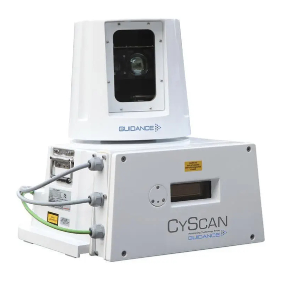
CyScan Sensor Part Names The diagram below shows the key parts of the sensor unit and the various names that are used throughout this guide: Optical Window Rotor Power Access Plate DP Feed Sensor Information Display Client Data Cable Gland Plate... - Page 9 CyScan Sensor Part Names (Continued) Power DP Feed 2 DP Feed 1 Client Data Alternative model with 4 cable glands.
-
Page 10: Serial Numbers & Software Versions
Serial Numbers & Software Versions Serial numbers and Software Version Numbers are used to identify the hardware configuration and product revision of each CyScan unit. They will be requested by Guidance Marine in the event of an application service support call to the company. -
Page 11: Sensor Information Display
Display Below is a list of the messages that appear during normal startup and operation of the CyScan Sensor. The messages are listed in the order they normally occur, when the system is left to startup and run without the user pressing any buttons. -
Page 12: Installing The Sensor Hardware
Installing the Sensor Hardware This section contains the following pages: • Where to Mount the Sensor (page 13) • Sensor Dimensions and Mounting Template (page 14) -
Page 13: Where To Mount The Sensor
Sensor Mounting Locations WARNING: If the CyScan sensor is mounted with the access plate facing towards the stern, the The CyScan system is designed for permanent or semi-permanent installation on-board a BOW/STERN switch on the connector board must be set to STERN. -
Page 14: Sensor Dimensions And Mounting Template ��������������������������������������������������������������14 Dp Message Types
WARNING: If the CyScan sensor is mounted with the access plate facing towards the stern, the BOW/STERN switch on the connector board must be set to STERN (see page 13). Allow a sensor height of 460mm... -
Page 15: Installing The Cables
Cable Specifications (page 16) • UPS Specifications (page 17) • CyScan Sensor Connections (page 18) • Client and DP Feed Connections - Ethernet Client, Serial DP (page 19) • Client and DP Feed Connections - Ethernet Client, Dual Serial DP (page 20) •... -
Page 16: Cable Specifications
Cable Specifications The CyScan system is usually supplied without the cables that are necessary to connect the sensor to the DP system and the Client Software computer(s). Guidance recommends that flexible multicore cables are used in all applications. Cables should meet the requirements of IEC 60228 Class 2 or Class 5. Cables must be supplied and fitted by the installer to match the particular requirements for each vessel. -
Page 17: Ups Specifications
• Peak Current draw = 1.5A RMS The CyScan UPS should be able to run on back-up power for at least the same duration as that specified for the DP System UPS. The power cable to the CyScan Sensor must be rated to withstand the maximum current output of the UPS. -
Page 18: Cyscan Sensor Connections
1. Having fed the cable through the watertight cable gland, use the key provided to open the ferrite and pass the cable through the centre of the ferrite. 2. Close the ferrite securely and ensure it is firmly attached to the inside of the CyScan casing to prevent excessive movement. -
Page 19: Client And Dp Feed Connections - Ethernet Client, Serial
Client and DP Feed Connections - Ethernet Client, Serial DP To connect an Ethernet Sensor with Ethernet to the Client and Serial to the DP Feed: Connect Ethernet Port 0 to the Client Computer and Serial Port 1 to the DP system. Configure the serial connections as shown below: To Connect Cables to RS422 Link... -
Page 20: Client And Dp Feed Connections - Ethernet Client, Dual Serial
Client and DP Feed Connections - Ethernet Client, Dual Serial DP To Connect an Ethernet Sensor with Ethernet to the Client and Serial to Two DP Systems: Connect Ethernet Port 0 to the Client computer, Serial Port 0 to DP System 1 and Serial Port 1 to DP system 2. Configure the serial connections as shown below: To Connect Cables to RS422 Link... -
Page 21: Client And Dp Feed Connections - Serial Client, Serial
7 GND 7 GND 7 GND 6 7 8 8 +24V 6 7 8 9 8 +24V 6 7 8 8 +24V Type 2 Marine CyScan Type 3 Marine CyScan Hatteland CyScan Processor Processor Panel PC Serial 0 Serial 0... -
Page 22: Installing The Control Pc
Installing the Control PC Before setting up the CyScan client computer(s), refer to the relevant installation sheet(s) for dimensions and connections information: For a Type 2 Marine Processor in a newly-installed system: • 94-0293-4 Type 2 Marine Processor and Display Installation Sheet For a Type 2 Marine Processor as a replacement for a Marine PC: •... -
Page 23: Installing Cyscan Client Software Onto A Type 2 Or 3 Marine Processor
Installing CyScan Client Software onto a Type 2 or 3 Marine Processor This section explains how to install the CyScan client software onto a Type 2 or 3 Marine Processor. If this Marine Processor has been supplied by Guidance Marine, it will have been shipped with the client software already installed. -
Page 24: Installing Cyscan Client Software Onto Other Types Of Computer
Full .NET Framework 4.0 or later • Visual C++ 2012 Redistributable (x86) If you are upgrading to newer versions of the CyScan client software, first uninstall the existing versions in the usual way, following on-screen prompts. Note: The CyScan Service Interface should... -
Page 25: Configuring The Cyscan System
Configuring the CyScan System This section contains the following pages: • Using the CyScan Service Interface (page 26) • Network Communication Settings (page 27) • Vessel Calibration (page 28) • Static Blanking Zones (page 30) • DP Feed Configuration (page 31) •... -
Page 26: Using The Cyscan Service Interface
Using the CyScan Service Interface Note: The CyScan Service Interface and CyScan Dashboard should not be run at the The CyScan Service Interface is a tool for configuring the CyScan system. same time. This can lead to communications problems with one or both applications. -
Page 27: Network Communication Settings
The Network Config tab of the CSI is used to view and amend the CSI’s definition of its communications link with the sensor, and to reconfigure the sensor’s own communications 1. Contact Guidance Marine and obtain a new sensor network configuration file (connect.ini). settings (e.g. from Serial to Ethernet mode). - Page 28 Vessel Breadth: The width or beam of the vessel in metres. • Bow Offset: Distance from the centre of the CyScan sensor to the vessel’s bow, in metres. • Starboard Offset: Distance from the centre of the CyScan sensor to the vessel’s starboard side, in metres.
- Page 29 Bearing Offset Reset, Import and Export of Vessel Calibration The CyScan Sensor should be aligned as closely as possible with the vessel’s centre-line, so The Vessel Calibration can be reset to factory defaults, imported from an XML or CTF file or the Bearing Offset should only need to be a few degrees at most.
-
Page 30: Static Blanking Zones
Zone section of the CyScan Operator’s Guide for further information. • Static Blanking Zones – Up to four additional blanking zones may also be configured. This is done using the CyScan Service Interface and the static blanking zones cannot be amended via the Dashboard. Viewing the Static Blanking Zones The Blanking tab of the CSI displays each of the configured zones and their Start and Stop angles in degrees. -
Page 31: Dp Feed Configuration
DP Feed Configuration The CyScan system provides positional data messages to your vessel’s DP (Dynamic Positioning) system and the format and behaviour of this output stream needs to meet the requirements of the DP system. The current DP configuration settings are displayed on the DP Config tab of the CSI, along DP Message Types with the most recent message emitted. - Page 32 DP Feed Configuration (Continued) DP Feed Behaviour for Multi-Target Tracking: Keep The DP Feed Behaviour options are two tick-boxes on the DP Config tab of the CSI:: Allow Zero Feed Output if Target is Lost Strings Keep Feed Enabled Enabled Allow Zero Strings Flag indicates stale data;...
-
Page 33: System Parameters
System Parameters When the CSI is in command mode, the Parameters tab displays a large number of settings and variables which define how the system behaves and describe its current state. They are arranged in groups (General, Core, Estimates, etc) and some of the parameters can be edited from the CSI. - Page 34 System Parameters (Continued) To Edit System Parameters The System Parameters can be reset to factory defaults, imported from an XML or PTF file or exported to an XML file. To Reset to Factory Defaults: 1. Ensure that no target tracking is in progress. 2.
-
Page 35: Additional Information
Sensor Information Display - Error Messages (page 50) • Upgrading the Sensor Software Via the Remote Installer (page 52) • Upgrading the Sensor Software Directly (page 53) • Remote Diagnostics (page 54) • The Kongsberg Maritime CyScan Sensor (page 55) • Index (page 59) -
Page 36: Target Types
Target Types CyScan can operate successfully with flat, cylindrical or prism targets. These can be bought online from www.marine.direct. Flat Targets Cylindrical Targets Prism Targets Flat targets are generally attached to rigid structures Cylindrical targets can be used up to Prism clusters with multiple 6cm elements such as metal stanchions using steel bands. -
Page 37: Positioning And Mounting Targets
Positioning and Mounting Targets Target Installation Key to the operation of the CyScan system is the correct installation of targets. Please follow the guidelines given below when installing targets on the structure/vessel. Once the targets are installed, their relative positions can be automatically surveyed by the system. -
Page 38: Nmea0183R Format
A - available; V - void • • HHHH status word in hexadecimal. Up to 16 bits defined by Guidance Marine in a HHHH status word in hexadecimal. Up to 16 bits defined by Guidance Marine in a separate specifications document separate specifications document. -
Page 39: Ascii17 Format
DP Message Types (Continued) † Nautronix Standard ASCII17 Format A 17 character string delimited only by <CR> and <LF> with bearing measured bow clockwise. A 14 character string delimited only by <CR> and <LF> with bearing measured bow clockwise. Character Index Description Format Character Index... -
Page 40: Mt Custom Dp String
Having a value for the Sequence identifier 1 char lag allows for subsequent correction of the measurement. • [IIII]I CyScan Responder ID [1-5] or RadaScan 16 bit Responder ID 1–5 chars • Status [V]oid or [N]avigating 1 char •... -
Page 41: Rolls-Royce Custom Dp String
Having a value for the [NNNN]N 16-bit revolution counter in decimal 1–5 chars lag allows for subsequent correction of the measurement. • [IIII]I CyScan Responder id [1-5] or RadaScan 16 bit Responder ID 1–5 chars • Status [V]oid or [N]avigating 1 char • [RRR]R.RR Range in metres 4–7 chars... -
Page 42: Part Numbers
Part Numbers Standard Components Reflective Targets (Optional) Component Part Number Component Part Number Mounting Template 94-0062-4 Flat 2m x 350cm 20-0031-0 Operator’s Guide 94-0353-4 Cylindrical 1.9m Ø 200mm 20-0078-0 Prism cluster, 8-way flexible 20-0075-1 Installer’s Guide 94-0363-4 Prism cluster, 8-way fixed 20-0134-1 DC4 Silicone Compound 98-0025-4... -
Page 43: Cyscan Mkiv Installation Checklist
CyScan MkIV Installation Checklist Vessel name: ................CyScan unit s/n: ..................Computer s/n: ............Check Requirement Checked Notes/record setting Check Requirement Checked Notes/record setting (Initial) (Initial) Mechanical Sensor Details / Vessel Calibration Sensor Line of sight to expected target positions... -
Page 44: Cable Routing Diagrams
Power Adaptor Marine Processor Power Cable Monitor Power Cable Note: The Ethernet cable connecting the CyScan Sensor to the Type 2 Marine DP System UPS Processor should not exceed 90 metres Emergency Breaker Box Ethernet in length. Please contact Guidance Marine if longer... - Page 45 Adaptor Marine Proces- Connection sor Power Cable Monitor Power Cable Note: The Ethernet cable connecting the CyScan Sensor to the Type 2 Marine DP System UPS Processor should not exceed 90 metres Emergency Breaker Box Ethernet in length. Ethernet Cable...
- Page 46 Adaptor Marine Processor Power Cable Monitor Power Cable Note: The Ethernet cable connecting DP System UPS the CyScan Sensor to the Type 2 Marine Emergency Breaker Box Processor should not exceed 90 metres Ethernet in length. Ethernet Cable Please contact Guidance Marine if longer P/N 33-0124-3 (40m) distances are required.
- Page 47 See page 49 for processor and monitor options CyScan Client DP Feed Power CyScan Monitor CyScan Sensor Monitor Cable CyScan Client Computer Power Adaptor Marine Processor Power Cable RS-422 Data Monitor Power Cable Data Cable P/N 33-0122-3 (40m) DP System UPS...
- Page 48 Cable See page 49 for processor and monitor options CyScan Client DP Feed Power CyScan Monitor CyScan Sensor Monitor Cable CyScan Client Computer Connection Power Adaptor Marine Processor Power Cable RS-422 Data Monitor Power Cable Data Cable P/N 33-0122-3 (40m)
- Page 49 Cable Routing Diagrams (Continued) Alternative Processor and Monitor Options Any of the following configurations may be used (see pages 44-48) Hatteland Hatteland CyScan Touchscreen Panel PC Monitor Monitor Monitor Cable Monitor Cable Type 2 Marine Processor Type 2 Marine Processor...
-
Page 50: Sensor Information Display - Error Messages
Sensor Information Display - Error Messages The Sensor Information Display shows the status of the sensor and its internal system throughout each period of operation. Sensor Information Display Details Below is a list of the messages that may appear if a problem occurs during operation, with descriptions of their meaning: Display Screen Message Description Checking components... - Page 51 Sensor Information Display - Error Messages (Continued) Sensor Information Display Details (Continued) Below is a list of the messages that may appear if a problem occurs during operation, with descriptions of their meaning: Display Screen Message Description Programming complete Programming of the CtrlApp was successful. Receiver Fatal Error The receiver has generated a fatal alarm and cannot start.
-
Page 52: Upgrading The Sensor Software Via The Remote Installer
Guidance Marine. To Upgrade the Sensor Software via the Remote Installer: 1. Ensure that the CyScan Service Interface and Dashboard applications are not running. 2. Locate the file CyScan.Installer.Remote.exe on the USB memory stick on which the CyScan software was supplied. -
Page 53: Upgrading The Sensor Software Directly
Upgrading the Sensor Software Directly If it is not possible to use the Remote Installer you can upgrade the sensor software directly Note: The USB upgrade key should be formatted to a FAT or FAT32 file system. using a USB upgrade key. You cannot use a USB upgrade key that is formatted to NTFS. -
Page 54: Remote Diagnostics
Remote Diagnostics An Ethernet CyScan system provides a remote diagnostics facility. The sensor autonomously emits diagnostic telegrams triggered by internal events and/or at configured periods. Remote Diagnostic Protocol The diagnostic telegram is of variable length, up to a maximum of 1000 characters. Its format is as follows: \s:NNNNNNNNNN*KK\$PGNMD,T,YYYY˽YY˽YY,HH˽HH˽HH.HHH,[D]D=[V]V*CC<CR><LF>... -
Page 55: The Kongsberg Maritime Cyscan Sensor
The Kongsberg Maritime CyScan Sensor This section describes aspects of the KM variant of the CyScan sensor that differ from those of the standard sensor. DP Message Types The KM CyScan sensor supports the following five DP message types: Kongsberg (Custom) The Kongsberg Custom DP string adopts NMEA0183 conventions and has a length of 40 characters. -
Page 56: Client And Dp Feed Connections - Ethernet Client, Serial Dp
The Kongsberg Maritime CyScan Sensor (continued) Client and DP Feed Connections - Ethernet Client, Serial DP To Connect an Ethernet Sensor with Ethernet to the Client and Serial to the DP Feed: Connect Ethernet Port 0 to the Client Computer and Serial Port 1 to the DP system. -
Page 57: Client And Dp Feed Connections - Ethernet Client, Dual Serial Dp
The Kongsberg Maritime CyScan Sensor (continued) Client and DP Feed Connections - Ethernet Client, Dual Serial DP To Connect an Ethernet Sensor with Ethernet to the Client and Serial to Two DP Systems: Connect Ethernet Port 0 to the Client Computer, Serial Port 0 to DP System 1 and Serial Port 1 to DP system 2. -
Page 58: Client And Dp Feed Connections - Serial Client, Serial Dp
The Kongsberg Maritime CyScan Sensor (continued) Client and DP Feed Connections - Serial Client, Serial DP RS422 Link Serial 1 9600 baud 8 bits 1 RX- To Connect a Serial Sensor with Serial to the Client and Serial to the DP Feed:... - Page 59 Sensor 7 ‘Going to running’ 50 Sensor Part Names 8 ‘Going to suspend’ 50 Targets 7 Access Plate 8 CyScan Service Interface 26 Armoured Cable 16 Artemis Mk IV 39 Kongsberg DP Strings ASCII17 39 Custom 55 Data Cable 16...
- Page 60 Index (Continued) Part Numbers 10 ‘Updating Blanking Zn’ 51 Sensor Cylindrical Target 36 ‘Updating receiver’ 51 Clearance 14 Flat Target 36 Connections 18 Upgrade Prism Target 36 Dimensions 14 Sensor 53 Power 8 Part Names 8 UPS Specifications 17 Cable 16 Upgrade 53 UV 16 Connections 18...
-
Page 61: Document History
Document History Document Number Changes Issue Date 94-0363-4-A First release of CyScan (Dashboard) Installer’s Guide 15th October 2013 94-0363-4-B Updated for CyScan v4.83 31st March 2014 94-0363-4-C Inclusion of the Marine brand and the 3 year warranty 31st May 2014 94-0363-4-D Updated for v4.9, including CyScan Service Interface...
Need help?
Do you have a question about the CyScan and is the answer not in the manual?
Questions and answers