
Related Manuals for GUIDANCE MARINE CyScan

Summary of Contents for GUIDANCE MARINE CyScan
- Page 1 CyScan Operator’s Guide Featuring CyScan Dashboard www.guidance.eu.com Guidance Marine Ltd, 4 Dominus Way, Meridian Business Park, Leicester LE19 1RP, UK +44 116 229 2600 E: sales@guidance.eu.com www.marine.direct...
- Page 2 No 50 26 Jul 2001 Copyright © 2015 Guidance Marine Limited. All Rights Reserved. Copyright in the whole and every part of this document belongs to Guidance Marine Limited (the “Owner”) and may not be used, sold, transferred, copied or reproduced in...
-
Page 3: Table Of Contents
Vessel Orientation �������������������������������������������������������������������������������������������������������20 Multi-Dashboard (Ethernet) CyScan Systems ......41 CyScan Ethernet Dashboard - Monitoring Mode �������������������������������������������������������42 Tracking Basics ..................21 CyScan Ethernet Dashboard - In Command Mode ���������������������������������������������������43 Blanking Zones �����������������������������������������������������������������������������������������������������������22 Setting the Blanking Zone ������������������������������������������������������������������������������������������������������������������� 22 Support Information ................44 Working with Reflections ��������������������������������������������������������������������������������������������23... - Page 4 Table of Contents (Continued) Troubleshooting ..................49 Problems and Possible Remedies������������������������������������������������������������������������������50 Cleaning the Sensor and Targets �������������������������������������������������������������������������������51 CyScan Fuse Information �������������������������������������������������������������������������������������������52 Additional Information ................53 Targets-Installation and Position ��������������������������������������������������������������������������������54 Low Temperature Operation ���������������������������������������������������������������������������������������56 Using the On Screen Keyboard ����������������������������������������������������������������������������������57 Working with Alarms ���������������������������������������������������������������������������������������������������58 Filtering Alarms ������������������������������������������������������������������������������������������������������������������������������������...
-
Page 5: Introduction
Introduction This section contains the following pages: • Welcome (page 6) • System Overview (page 7) • CyScan Sensor Part Names (page 8) -
Page 6: Welcome
(see page 9) explains the basics that you’ll need to know before using the CyScan system for the first time. The CyScan system can be installed either as a single-Dashboard serial system or as a multi-Dashboard Ethernet system. The majority of the sections in this guide apply equally for serial or Ethernet configured... -
Page 7: System Overview
This provides the DP operator with status information and control of the system and the data stream being fed to the DP system. The CyScan Service Interface is used for system installation and maintenance. This replaces the Service Access function in earlier versions of the CyScan Dashboard and Console. -
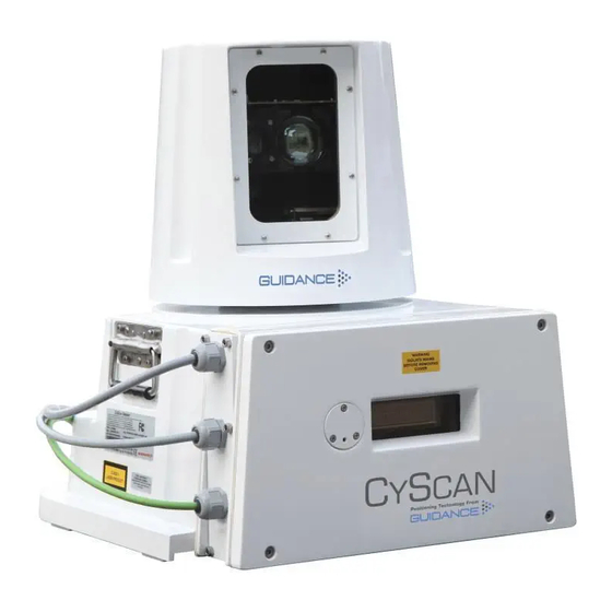
Page 8: Cyscan Sensor Part Names
CyScan Sensor Part Names The diagram below illustrates various parts of the sensor unit and gives the terms used for them. Optical Window Rotor Power Access Plate DP Feed Sensor Information Display Client Data Cable Gland Plate Base Plate... -
Page 9: Getting Started
Getting Started This section contains the following pages: • Start Up and Shut Down (page 10) • Screen Layout (page 11) • Tracking Information Quality (page 18) • Display Settings (page 19) • Vessel Orientation (page 20) You may also find the following sections of the Appendices useful at this stage: •... -
Page 10: Start Up And Shut Down
Command/Monitoring Dashboard only). • functionality. Suspend And Exit - Places the sensor into the same ‘sleep mode’ as the suspend command (discussed above) and also closes the CyScan Dashboard program. • Serial Dashboard Dashboard Exit - Closes down the Dashboard without affecting the sensor. -
Page 11: Screen Layout
Screen Layout The CyScan Dashboard screen is split into three distinct sections, these are: • Main Screen and Bird's Eye View (BEV) (see page • Side Bar (see page 14) • Menu Pane (see page... -
Page 12: Main Screen And Bird's Eye View (Bev)
View (BEV) Heading Tag Status Display Data Logging The centre of the circular BEV represents Indicator the CyScan sensor and it shows the relative Blanking Zone positions of the CyScan vessel and any detected Drag Handles reflections. Vessel Outline Vessel Outline... - Page 13 Screen Layout (Continued) Reflection Images Reflections received by the sensor are displayed as yellow circles. For tracking you must select the reflection(s) that correspond to the physical target(s) to be used. During multi-target tracking, grey boxes are drawn around the selected reflections to indicate a strong association with the target (i.e.
-
Page 14: Side Bar
Screen Layout (Continued) Side Bar The Side Bar, the black pane to the left of the BEV, contains control and display components in addition to the coordinates pane. Toggle Coordinate Type Signal Quality Coordinate Data DP Message Format After pressing the Guidance button: Current Tilt Mode and Command Mode... -
Page 15: Hotkey Buttons
Screen Layout (Continued) Hotkey Buttons Selecting the Hotkeys tab on the right-hand side of the main screen activates the Dashboard Hotkeys menu. The following keys - and the corresponding buttons on the Dashboard Hotkeys menu - act as shortcuts to application functions. Help Menu Rotates the vessel clockwise Rotates the vessel counter-clockwise... -
Page 16: Menu Pane
Menu Pane The Menu Pane, located across the bottom of the CyScan Dashboard Screen, is not always visible. It appears when one of the Tracking, Tilt or Advanced buttons near the foot of the Side Bar are pressed, which causes the Bird's Eye View (BEV) to contract towards the top of the screen. -
Page 17: Coordinates View
Screen Layout (Continued) Coordinates View Whilst tracking is in progress, the positional coordinates and the Bird’s Eye View can be transposed, so that the coordinates are displayed in extra-large numerals on the main screen, whilst a miniature BEV is shown at the top of the side bar. If tracking ends, the layout automatically reverts to Bird’s Eye View, but as long as Coordinates View remains selected, the main screen will again display coordinates once the next tracking operation commences. -
Page 18: Tracking Information Quality
The CyScan Sensor rotates anti-clockwise. On each rotation, the sensor emits a beam of infrared laser light and analyses the position of any reflections that it receives. After several rotations, the sensor is able to compare the reflections received on the last rotation with those received during previous rotations. This enables CyScan to recognise the reflections from the intended targets and to ignore any unwanted reflections. -
Page 19: Display Settings
Display Settings To provide ample visibility during daytime operation and to limit glare during night shifts, CyScan Dashboard offers two display settings: Day Mode and Night Mode. In either mode the brightness can be further adjusted by the Screen Brightness control. -
Page 20: Vessel Orientation
Vessel Orientation CyScan Dashboard supports four different layouts of the Bird’s Eye View so that the operator can choose the one which best represents his surroundings. For instance, if the operator is facing forward when using the Dashboard, he may want the bow of the vessel in the BEV to point upwards, so that targets located on the starboard side of the vessel are shown on the right-hand side of the BEV. -
Page 21: Tracking Basics
Tracking Basics This section contains the following pages: • Blanking Zones (page 22) • Working with Reflections (page 23) • Scanner Tilt Controls (page 25) -
Page 22: Blanking Zones
Blanking Zones The Blanking Zone is used to mask a segment of the scan rotation. When the scanner passes through the blanking zone, the laser is switched off to prevent any unwanted reflections from being mistaken as targets. N.B. Even if the sensor has a clear 360° view, there must be a blanking zone of at least 23°. -
Page 23: Working With Reflections ��������������������������������������������������������������������������������������������23 Support Information
Working with Reflections Basic Refections Data a. Filtering by Range Reflections data is displayed on two panes accessed via the Tracking Button. The Allows the user to discard reflections that are closer than the threshold range. For example, Reflections pane contains a list of reflections that are visible to the scanner, and the Range, setting the range threshold to 35m will cause any reflections from less than 35m away to be discarded. -
Page 24: Extended Reflection Data
Extended Reflection Data The Reflection Pulses pane contains details about the number of pulses that make up each Rev # - The total number of revolutions made by the scanner rotor since CyScan was last reflection, and their angle of incidence. -
Page 25: Scanner Tilt Controls ��������������������������������������������������������������������������������������������������25 To View Dp Feed Details
Manual - This mode is used to manually tilt the optics to reach the target. For example, when station-keeping close to a platform where the targets are mounted Manually Tilting the high up and the CyScan optics must be tilted up at them. (See Scanner on page 26). -
Page 26: Manually Tilting The Scanner
The Manual mode is used to tilt the scanner optics to a user-defined angle so that the centre of the fanned beam is pointing at the target. This may be necessary when the CyScan Vessel is close to a platform and the targets are positioned above the sensor. Upper Channel... -
Page 27: Single And Multi-Target Tracking
This section explains the different types of target tracking that can be performed using the CyScan Dashboard, and how to configure them. It does not provide advice on how to set up a tracking operation for a specific DP system or application. -
Page 28: Introduction To Single And Multi-Target Tracking
Introduction to Single and Multi-Target Tracking For Multi-Target Mode The CyScan system can track either a single target or multiple targets: Selecting 1. Select a minimum of two and a maximum of five target reflections (see Single-Target Tracking Targets for Multi-Target Tracking on page 31). -
Page 29: Positional Display Modes
Positional Display Modes The relative positions of the CyScan vessel and single or multiple targets can be expressed Range & Bearing either as Range and Bearing values, or as 'x' and 'y' positions on a rectangular coordinate Range and Bearing mode displays the distance and the bearing of the primary (or only) frame. -
Page 30: Bow And Starboard Axes
Positional Display Modes (Continued) Bow and Starboard Axes This mode is available for single-target tracking, and for multi-target tracking where the DP feed messages are sent in NMEA0183P (primary) format. In this mode, the position of the sensor vessel is expressed in metres from the target along Bow (B) and Starboard (S) axes which have their origin at the primary (or only) target. -
Page 31: Selecting Targets For Multi-Target Tracking
Vessel removed and not just omitted from the multi-target group. CyScan tracks targets more accurately when multiple targets are spaced asymmetrically (see right). If the targets are not spaced asymmetrically, it is better to operate with fewer (i.e. 2) targets. -
Page 32: Target Selection Order
Selecting Targets for Multi-Target Tracking (Continued) Target Selection Order Any additional targets (targets 3-5) should be spaced asymmetrically between the primary and secondary targets The first target selected The second target (the primary) becomes the selected (the secondary) origin of the coordinate axes. sets the default direction of the A axis. -
Page 33: Target Selection Order And Coordinate Axes Direction
Axis A runs from right to left. • • Axis B points towards the CyScan vessel. Axis B points away from the CyScan vessel. The left-most reflection is selected as target 1 and the The right-most reflection is selected as target 1 and the Target right-most reflection as target 2. -
Page 34: Axis Orientation And Vessel Heading
A axis to the perpendicular of a line passing through targets 1 and 2. The default orientation value depends on the relative positions of the targets: • If target 1 is on the left when viewed from the CyScan vessel, the default target orientation value is 90°. •... -
Page 35: Vessel Heading
Axis Orientation and Vessel Heading (Continued) Vessel Heading Vessel Heading is measured clockwise from the origin of the A axis to the CyScan vessel’s centre-line. The vessel’s relative heading value depends on the orientation of the coordinate axes. Changing the orientation of the A axis also changes the vessel’s relative heading. -
Page 36: Rotational Offsets
Rotational Offsets Some DP systems and applications may require the A and B coordinate axes to be rotated Target 1 to match a different heading. For example, to line-up with the DP System’s own co- ordinate axes, the axes of another sensor, the vessel’s gyrocompass, or any other heading Target 2 (Origin) value. -
Page 37: Axis Orientation And Vessel Heading Examples
Rotational Offsets (Continued) Axis Orientation and Vessel Heading Examples In the following examples, the CyScan vessel’s relative heading to the multi-target group remains constant, and the coordinate axes are rotated clockwise about their origin (target Aligning Multi-Target Heading with the Ship’s Compass 1). - Page 38 Rotational Offsets (Continued) Axis Orientation and Vessel Heading Examples (Continued) 270° 180° 270° Target 1 Target 2 Target 1 Target 2 (Origin) (Origin) 180° 180° 90° Vessel Vessel Target Coordinate axes rotated 180° clockwise from default position. Coordinate axes rotated 270° clockwise from default position. •...
- Page 39 Changes to the orientation of the A and B axes affect the A Pos and B Pos coordinates of the targets and the CyScan Sensor. In the following examples, the vessel’s relative position to the multi-target group remains constant, but the reported ‘A Pos’ and ‘B Pos’...
-
Page 40: Aligning Multi-Target Heading With The Ship's Compass
Rotational Offsets (Continued) Aligning Multi-Target Heading with the Ship’s Compass If you require CyScan to produce a heading based on geographic North rather than on the orientation of the primary and secondary targets, follow the instructions below. These cause the A and B axes and position coordinates to be recalculated accordingly. -
Page 41: Multi-Dashboard (Ethernet) Cyscan Systems
CyScan Ethernet Dashboard - In Command Mode (see page 43) Note that a CyScan system running with Serial communications supports only a single Dashboard, and whenever this is running and connected to the sensor, it is effectively in command mode. -
Page 42: Cyscan Ethernet Dashboard - Monitoring Mode
When the Dashboard is running in Monitoring mode, the controls relating to the Dashboard itself will be active, but those relating to the CyScan sensor will be disabled. A Monitoring Dashboard displays the same reflections and positional data as the Command Dashboard, although it is updated at a reduced rate (every 3-4 seconds instead of every second). -
Page 43: Cyscan Ethernet Dashboard - In Command Mode
Dashboard, whether it is Monitoring or In Command. If there was already an In When the In Command Dashboard is used to suspend the CyScan sensor, a message Command Dashboard in the will appear on the screens of the Monitoring Dashboards indicating that the system is suspended. - Page 44 Support Information This section contains the following pages: • Serial Numbers and Software Versions (page 45) • DP Feed (page 46) • Manual Power Control (page 47) • Data Logging (page 48)
-
Page 45: Serial Numbers And Software Versions
Serial Numbers and Software Versions These numbers identify the hardware configuration and product revision and will be requested by Guidance Marine in the event of an application service or support call to the company. Product Label The Part Number and Serial Number can be found on the product label affixed to each unit. -
Page 46: Dp Feed
CyScan and the DP system are both configured to use matching formats. However, this cannot be done from the Dashboard; in order to change the CyScan DP settings, use the CyScan Service Interface (see document 94-0363-4 CyScan Installer's Guide, which also contains descriptions of the available DP message formats). -
Page 47: Manual Power Control
Manual Power Control Manual Power Control can be used to switch off the normal automatic power control for the rotor on the CyScan Sensor and to apply and adjust a fixed constant power instead. To Enable Manual Power Control: 1. Click on the Tracking button on the side bar. -
Page 48: Data Logging
DP Supplier in the event of a problem. computer. To Export Data Logs On a CyScan system with multiple Dashboards, data logs are written by whichever Dashboard is in command. If another Dashboard then takes command, the location of 1. Insert a USB or other the logs from that time forward will also change. -
Page 49: Troubleshooting
Troubleshooting If you experience problems when installing or using the CyScan system, please check through this Troubleshooting section for a possible solution. It contains the following pages: • Problems and Possible Remedies (page 50) • Cleaning the Sensor and Targets (page 51) •... -
Page 50: Problems And Possible Remedies
Problems and Possible Remedies No communication between CyScan Dashboard and the Sensor System appears to be operational but no reflections are displayed • within CyScan Dashboard The Dashboard screen turns grey, the Primary Status Display reads “System ERROR” • and the Secondary reads “Comms timed out”. Click the Connect button. -
Page 51: Cleaning The Sensor And Targets
Cleaning the Sensor and Targets To maintain the CyScan Sensor in good working order it is important that its optical elements are kept free of contamination. To clean the optical window Use a lint-free cloth with IPA spray to carefully wipe the optical window. -
Page 52: Cyscan Fuse Information
CyScan Fuse Information The CyScan system contains two replaceable fuses, one for the Live and the other for the Neutral. These are located on the connector board as shown below. Connector Board Fuse Please refer to the Installer’s Guide for details on how to access the connector board. -
Page 53: Additional Information
Targets-Installation and Position (page 54) • Low Temperature Operation (page 56) • Using the On Screen Keyboard (page 57) • Working with Alarms (page 58) • CyScan System Specifications (page 61) • Index (page 62) • Document History (page 64) -
Page 54: Targets-Installation And Position
Targets-Installation and Position CyScan can operate successfully with flat, cylindrical or prism targets. These can be bought online from www.marine.direct. Flat Targets Cylindrical Targets Prism Targets Flat targets are generally attached to rigid structures Cylindrical targets can be used up to Prism clusters with multiple 6cm elements such as metal stanchions using steel bands. - Page 55 Targets-Installation and Position (Continued) Target Installation Key to the operation of the CyScan system is the correct installation of targets. Please follow the guidelines given below when installing targets on the structure/vessel. Once the targets are installed, their relative positions can be automatically surveyed by the system.
-
Page 56: Low Temperature Operation
The CyScan hardware complies with the requirements of IEC 60068-2-1 and is able to operate for prolonged periods at temperatures down to – 25°C provided that certain operating conditions are maintained. -
Page 57: Using The On Screen Keyboard
Using the On Screen Keyboard In order to accommodate systems without keyboards, CyScan Dashboard provides an In the case of a numerical field, the OSK is restricted to the appropriate keys: onscreen Keyboard (OSK) option. This enables text to be input using only a mouse pointer or touch screen. -
Page 58: Working With Alarms
Working with Alarms Filtering Alarms During operation, the CyScan system produces an audit trail of event messages. These range in increasing order of severity from: Information, Warning, and Error to Fatal. As A filter is available to suppress the display of particular alarm types. By default, the filter is these alarms are raised, the Dashboard lists them within the Alarms pane. -
Page 59: Using The Historic Alarm List
Using the Current and Historic Alarms Lists Using the Historic Alarm List The Alarms tab has two alarms lists: • The Current Alarms List displays new alarms (since the last start of the Dashboard software). • The Historic Alarms List is used to store alarms that have been cleared from the current list. -
Page 60: Network Communications Settings
The Comms Settings menu pane displays the configuration of communications between the Dashboard and sensor. In the case of Ethernet comms, the IP address can be modified at the Dashboard; otherwise these settings should be modified using the CyScan Service Interface (see document 94-0363-4 CyScan Installer's Guide). -
Page 61: Cyscan System Specifications
CyScan System Specifications Sensor Vessel Interface Laser Type Pulsed (min. 30kHz) semiconductor laser diode (904nm) Power Requirement 85-264VAC, 45-65Hz, max100W, 1.5A (fuse) Laser Classification Eye safe to Class 1 IEC 60825 Sensor Control and DP Feed I/O 2 x RS422 + 2 x Ethernet 100Base-T Auto MDI/X Beam Shape (nominal) 12°... -
Page 62: Index
Manually Tilting the Scanner 26 Clear Alarms 59 Manual Power Control 47 Contact Details 49 Multiple Target Spacing 55 Guidance Marine 49 Multi-Target Tracking 27 Coordinate Axes Direction 33 Cylindrical Targets 54 CyScan Sensor Part Names 8 Operating Conditions 56 Optical Window 8... - Page 63 Controls 25 Selecting Reflections 31 Selecting Targets 31 Vessel Heading Sensor Part Names 8 Examples 37 Serial Number CyScan Sensor 45 Single-target navigation 27 Slave 42 Software Versions 45 Spacing Multiple Targets 55 Starboard Axes 30 Sub-zero Temperatures 56 System Logging 48...
-
Page 64: Document History
94-0353-4-A First release of CyScan (Dashboard) Operator's Guide 15/10/2013 94-0353-4-B Updated for CyScan v4.83 31/03/2014 94-0353-4-C Inclusion of the Marine brand and the 3 year warranty 31/05/2014 94-0353-4-D Removal of Service Access functionality and other changes for CyScan v4.9 28/08/2015...
Need help?
Do you have a question about the CyScan and is the answer not in the manual?
Questions and answers