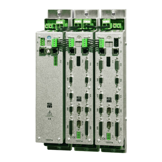
SIEB & MEYER SD2 Hardware Description
Drive system
Hide thumbs
Also See for SD2:
- Hardware description (196 pages) ,
- Translation of the original instructions (66 pages) ,
- Manual (34 pages)

Related Manuals for SIEB & MEYER SD2


Summary of Contents for SIEB & MEYER SD2
- Page 1 SIEB & MEYER Drive System SD2 Hardware Description Drive amplifier SD2, power supply unit PS2 P-TD-0000205.7 2016-04-13...
- Page 2 Min-Sheng N. Road Fairfield, OH 45014 Kwei-Shan Hsiang 333 Tao-Yuan Hsien Phone: +1 513 563 0860 Taiwan Fax: +1 513 563 7576 Phone: +886 3 311 5560 info@sieb-meyerusa.com Fax: +886 3 322 1224 http://www.sieb-meyer.com smasia@ms42.hinet.net http://www.sieb-meyer.com Drive System SD2 - Hardware Description...
-
Page 3: Table Of Contents
Mounting Example with Heat Sink Integrated Water-cooled Heat Sink Connector Pin Assignment Connection Examples System Connection Status Display and Error Messages of SD2 Status Display and Error Messages of PS2 General Information Regarding the Wiring Electric Performance Dimensioning Drive System SD2 - Hardware Description... - Page 4 Chapter Overview Safety Circuit / Restart Lock Appendix Index Drive System SD2 - Hardware Description...
- Page 5 Heat Sink ....................6.4.1 Dimensions ......................6.4.2 Technical Data ...................... 6.4.3 Connectors ......................Device Variant 0362114xy (max. 80 A) with Integrated Heat Sink ... 6.5.1 Dimensions ......................6.5.2 Technical Data ...................... 6.5.3 Connectors ......................Drive System SD2 - Hardware Description...
- Page 6 Extruded Heat Sink Made of Aluminum ............ 10.3 High-performance Heat Sink ..............10.4 Mounting Holes for 70 mm Devices ............10.5 Mounting Holes for 100 mm Devices ............10.6 Mounting Holes for 130 mm Devices ............Drive System SD2 - Hardware Description...
- Page 7 EnDat 2.1 with Sine Signals (1 V ) ..............13.7.4 Hiperface with Sine Signals ................13.7.5 SSI Encoder ......................13.7.6 Hall Sensor 12 V ....................13.7.7 Hall Sensor 5.3 V ....................13.7.8 Field Plate ......................Drive System SD2 - Hardware Description...
- Page 8 Analog Outputs ....................13.11 X22/X24 – Motor Phases ................ 13.12 X26/X27 – SERVOLINK ................System Connection ............Status Display and Error Messages of SD2 ....15.1 List of the Operating States ..............15.2 List of Drive Error Messages ..............15.3 List of Warning Messages ...............
- Page 9 Content 20.D.1 SIEB & MEYER Accessories ................20.D.1.1 Connectors of the Series SD2 ................20.D.1.2 Line Filters for Frequency Converter/Power Electronics ........20.D.1.3 SERVOLINK 4 Master PCI Plug-in Board 036500001 ........20.D.1.4 USB>RS232/485 Converter 050201 ..............20.D.2 Phoenix Contact ....................
- Page 10 Content Drive System SD2 - Hardware Description...
-
Page 11: About This Manual
Indicates a hazardous situation which, if not avoided, may result in property damage. Risk symbols Risk symbol Description General hazardous situation Risk of injury due to electric shock Risk of injury due to hot surfaces Drive System SD2 - Hardware Description... -
Page 12: Illustration Of General Notices
OSSD Output Signal Switching Device SERVO servo control safety function: Safe Torque Off sensorless vector control V/f Characteristic Curve voltage at the common collector VECTOR vector control Drive System SD2 - Hardware Description... -
Page 13: General Information
General Information General Information This manual describes the drive systems of the series SD2. These devices allow oper‐ ation of high-dynamic servo motors as well as synchronous and asynchronous high- frequency spindles. The devices are equipped with interfaces for different sensor systems allowing to drive motors with resolvers as well as SinCos, EnDat, Hall, linear Hall, incremental and field plate sensors. - Page 14 General Information Drive System SD2 - Hardware Description...
-
Page 15: Safety Instructions
Consider the relevant notes in the manual. WARNING Risk of injuries and material damage due to illegal modifications Only change the settings of the device after having contacted SIEB & MEYER. Drive System SD2 - Hardware Description... -
Page 16: Appropriate Use
(installation of heating/air condi‐ tioning systems etc.): ▶ The storage area must be clean (dust-free, if possible), dry and well-ventilated. ▶ Storage in the open is not permitted. Drive System SD2 - Hardware Description... -
Page 17: Installation
The admissible relative humidity is between 5 % and 85 % (no bedewing). ▶ The admissible ambient temperature during operation is +5 °C to +40 °C (+41 °F to +104 °F). Extreme and sudden changes of the temperature should be prevented. Drive System SD2 - Hardware Description... -
Page 18: Electrical Connection
After turning off the unit hazardous voltages may still exist for up to 3 minutes in the power supply (due to capacitors). ➮ Never connect capacitive loads to the output phases of the servo amplifiers and frequency converters. Drive System SD2 - Hardware Description... -
Page 19: Operation
Risk of serious injuries due to moving machine parts During the operation of an installation with open doors or removed covers, persons may seriously be injured by moving machine parts. Keep the doors closed during the operation and do not remove covers. Drive System SD2 - Hardware Description... -
Page 20: Maintenance
SIEB & MEYER and the customer. NOTICE Due diligence of the machine manufacturer A first programming carried out by SIEB & MEYER does not release the machine manufacturer from his duty to check the programmed values for correctness. Drive System SD2 - Hardware Description... -
Page 21: Unit Assembly Complying Emc
High-frequency interferences may occur, if the device is used in a public mains which supplies residential areas. These interferences may disturb the functioning of other devices. Do not use the device in a public mains or ensure appropriate interference suppression measures. Drive System SD2 - Hardware Description... - Page 22 Unit Assembly Complying EMC Drive System SD2 - Hardware Description...
-
Page 23: Drive Amplifier Sd2
Drive Amplifier SD2 Drive Amplifier SD2 Block Diagram Fig. 1: Block diagram SD2 Drive System SD2 - Hardware Description... -
Page 24: Type Plate
Indicates the version of the hardware; if no version is existent, 0.000 is indicated here IP Code Indicates the level of protection of the device against touching or intrusion of solid objects (1st digit) and water ingress (2nd digit) QA label Drive System SD2 - Hardware Description... -
Page 25: Device Designation
F = up to 675 V Current range ▶ see technical data Specific type code ▶ 10 - 15 = drive amplifiers SD2 ▶ 30, 31 = compact device SD2 ▶ 90, 91 = power supply unit PS2 Module type ▶... -
Page 26: Components Of The Drive System Sd2X
The following list contains all other devices of the drive system SD2x. These devices are described in separate documents. The article numbers of these devices begin with 0362X: ▶ 036231X: SD2 drive amplifiers including the safety functions SFM and SLOF ▶ 036212X: SD2S Light compact devices ▶... -
Page 27: Single-Axis Drive Amplifiers
For sufficient cooling the ventilation inlets and outlets must be kept free by a space of min. 10 cm. The device is designed for vertical wall mounting. Other setup positions are possible but you must consult SIEB & MEYER before. Drive System SD2 - Hardware Description... -
Page 28: Dimensions
When installing the first and the last module, consider that the heads of the cabinet screws located on the long sides of each module overlap up to 2 mm. Since the screws are fastened staggered to each other, this is negligible between two modules. Drive System SD2 - Hardware Description... -
Page 29: Technical Data
Max. weight 3 kg The device variants 0362111MF and 0362111NF are described here, page The rated power values are maximum values, that means they apply when optimum cooling is provided by a heat sink. Drive System SD2 - Hardware Description... -
Page 30: Connectors
SERVOLINK 4 optical output page 113 Fig. 6: Bottom view Fig. 5: Front view You can order the appropriate connector kit for the device variant 0362111xy (article No. 322 99 542) at SIEB & MEYER. Drive System SD2 - Hardware Description... -
Page 31: Device Variant 0362111Mf/0362111Nf (Max. 200 A)
For sufficient cooling the ventilation inlets and outlets must be kept free by a space of min. 10 cm. The device is designed for vertical wall mounting. Other setup positions are possible but you must consult SIEB & MEYER before. Drive System SD2 - Hardware Description... -
Page 32: Dimensions
When installing the first and the last module, consider that the heads of the cabinet screws located on the long sides of each module overlap up to 2 mm. Since the screws are fastened staggered to each other, this is negligible between two modules. Drive System SD2 - Hardware Description... -
Page 33: Technical Data
100 % rated current up to max. 40 °C. At higher temperatures the power must be reduced by -1.5 % per 1 °C. IP Code IP20 Max. weight 9 kg The rated power values are maximum values, that means they apply when optimum cooling is provided by a heat sink. Drive System SD2 - Hardware Description... -
Page 34: Connectors
SERVOLINK 4 optical output page 113 Fig. 9: Front view Fig. 10: Bottom view You can order the appropriate connector kit for the device variant 0362111MF/0362111NF (article No. 322 99 547) at SIEB & MEYER. Drive System SD2 - Hardware Description... -
Page 35: Integrated Water-Cooled Heat Sink
The device is designed for vertical wall mounting. Other setup positions are possible but you must consult SIEB & MEYER before. For further information on the water cooling refer to chapter 11 "Integrated Water- cooled Heat Sink", page Drive System SD2 - Hardware Description... -
Page 36: Dimensions
When installing the first and the last module, consider that the heads of the cabinet screws located on the long sides of each module overlap up to 2 mm. Since the screws are fastened staggered to each other, this is negligible between two modules. Drive System SD2 - Hardware Description... -
Page 37: Technical Data
-1.5 % per 1 °C. IP Code IP20 Max. weight 5.9 kg The rated power values are maximum values, that means they apply when optimum cooling is provided by a heat sink. Drive System SD2 - Hardware Description... -
Page 38: Connectors
SERVOLINK 4 optical output page 113 Fig. 13: Front view Fig. 14: Bottom view You can order the appropriate connector kit for the device variant 0362111OF (article No. 322 99 547) at SIEB & MEYER. Drive System SD2 - Hardware Description... -
Page 39: Device Variant 0362111Rf (Max. 220 A) With Integrated Water-Cooled Heat Sink
The device is designed for vertical wall mounting. Other setup positions are possible but you must consult SIEB & MEYER before. For further information on the water cooling refer to chapter 11 "Integrated Water- cooled Heat Sink", page Drive System SD2 - Hardware Description... -
Page 40: Dimensions
Single-axis Drive Amplifiers 6.4.1 Dimensions Fig. 16: Dimensions 0362111RF in mm (inch) Drive System SD2 - Hardware Description... -
Page 41: Technical Data
-1.5 % per 1 °C. IP Code IP20 Max. weight 8.7 kg The rated power values are maximum values, that means they apply when optimum cooling is provided by a heat sink. Drive System SD2 - Hardware Description... -
Page 42: Connectors
The connectors for the motor (U, page V, W) and the DC link (+UB,−UB) Motor are located under the device phases cover. Therefore, you should wire these connectors at first. Fig. 18: Bottom view Drive System SD2 - Hardware Description... -
Page 43: Device Variant 0362114Xy (Max. 80 A) With Integrated Heat Sink
For sufficient cooling the ventilation inlets and outlets must be kept free by a space of min. 10 cm. The device is designed for vertical wall mounting. Other setup positions are possible but you must consult SIEB & MEYER before. Drive System SD2 - Hardware Description... -
Page 44: Dimensions
For the installation consider that the heads of the cabinet screws located on the long sides of each module overlap up to 2 mm. This causes a module gap of at least 4 mm when several modules are combined in an assembly group. Drive System SD2 - Hardware Description... -
Page 45: Technical Data
100 % rated current up to max. 40 °C. At higher temperatures the power must be reduced by -1.5 % per 1 °C. IP Code IP20 Max. weight 5.7 kg The device variants 0362114MF and 0362114NF are described here, page Drive System SD2 - Hardware Description... -
Page 46: Connectors
SERVOLINK 4 optical output page 113 Fig. 22: Bottom view Fig. 21: Front view You can order the appropriate connector kit for the device variant 0362114xy (article No. 322 99 542) at SIEB & MEYER. Drive System SD2 - Hardware Description... -
Page 47: Device Variant 0362114Mf/0362114Nf (Max. 200 A) With Integrated Heat Sink
For sufficient cooling the ventilation inlets and outlets must be kept free by a space of min. 10 cm. The device is designed for vertical wall mounting. Other setup positions are possible but you must consult SIEB & MEYER before. Drive System SD2 - Hardware Description... -
Page 48: Dimensions
For the installation consider that the heads of the cabinet screws located on the long sides of each module overlap up to 2 mm. This causes a module gap of at least 4 mm when several modules are combined in an assembly group. Drive System SD2 - Hardware Description... -
Page 49: Technical Data
5 °C to 60 °C at a maximum relative humidity of 85 % (without moisture condensation), 100 % rated current up to max. 40 °C. At higher temperatures the power must be reduced by -1.5 % per 1 °C. IP Code IP20 Max. weight 9.3 kg Drive System SD2 - Hardware Description... -
Page 50: Connectors
SERVOLINK 4 optical output page 113 Fig. 25: Front view Fig. 26: Bottom view You can order the appropriate connector kit for the device variant 0362114MF/0362114NF (article No. 322 99 547) at SIEB & MEYER. Drive System SD2 - Hardware Description... -
Page 51: Double-Axis Drive Amplifiers
For sufficient cooling the ventilation inlets and outlets must be kept free by a space of min. 10 cm. The device is designed for vertical wall mounting. Other setup positions are possible but you must consult SIEB & MEYER before. Drive System SD2 - Hardware Description... -
Page 52: Dimensions
When installing the first and the last module, consider that the heads of the cabinet screws located on the long sides of each module overlap up to 2 mm. Since the screws are fastened staggered to each other, this is negligible between two modules. Drive System SD2 - Hardware Description... -
Page 53: Technical Data
100 % rated current up to max. 40 °C. At higher temperatures the power must be reduced by -1.5 % per 1 °C. IP Code IP20 Max. weight 3 kg The rated power values are maximum values, that means they apply when optimum cooling is provided by a heat sink. Drive System SD2 - Hardware Description... -
Page 54: Connectors
SERVOLINK 4 optical output page 113 Fig. 30: Bottom view Fig. 29: Front view You can order the appropriate connector kit for the device variant 0362110xxy (article No. 322 99 541) at SIEB & MEYER. Drive System SD2 - Hardware Description... -
Page 55: Device Variant 0362112Xxy (Max. 120 A)
For sufficient cooling the ventilation inlets and outlets must be kept free by a space of min. 10 cm. The device is designed for vertical wall mounting. Other setup positions are possible but you must consult SIEB & MEYER before. Drive System SD2 - Hardware Description... -
Page 56: Dimensions
When installing the first and the last module, consider that the heads of the cabinet screws located on the long sides of each module overlap up to 2 mm. Since the screws are fastened staggered to each other, this is negligible between two modules. Drive System SD2 - Hardware Description... -
Page 57: Technical Data
100 % rated current up to max. 40 °C. At higher temperatures the power must be reduced by -1.5 % per 1 °C. IP Code IP20 Max. weight 3.8 kg The rated power values are maximum values, that means they apply when optimum cooling is provided by a heat sink. Drive System SD2 - Hardware Description... -
Page 58: Connectors
Connection of the motor phases page 111 X24B Connection of the motor phases page 111 SERVOLINK 4 optical input page 113 SERVOLINK 4 optical output page 113 Fig. 33: Front view Fig. 34: Bottom view Drive System SD2 - Hardware Description... -
Page 59: Device Variant 0362113Xxy (Max. 40 A) With Integrated Heat Sink
You can order the appropriate connector kit for the device variant 0362112xxy (article No. 322 99 543) at SIEB & MEYER. Device Variant 0362113xxy (max. 40 A) with Integrated Heat Sink Fig. 35: Device view 0362113xxy Drive System SD2 - Hardware Description... - Page 60 For sufficient cooling the ventilation inlets and outlets must be kept free by a space of min. 10 cm. The device is designed for vertical wall mounting. Other setup positions are possible but you must consult SIEB & MEYER before. Drive System SD2 - Hardware Description...
-
Page 61: Dimensions
For the installation consider that the heads of the cabinet screws located on the long sides of each module overlap up to 2 mm. This causes a module gap of at least 4 mm when several modules are combined in an assembly group. Drive System SD2 - Hardware Description... -
Page 62: Technical Data
5 °C to 60 °C at a maximum relative humidity of 85 % (without moisture condensation), 100 % rated current up to max. 40 °C. At higher temperatures the power must be reduced by -1.5 % per 1 °C. IP Code IP20 Max. weight 5.7 kg Drive System SD2 - Hardware Description... -
Page 63: Connectors
SERVOLINK 4 optical output page 113 Fig. 38: Bottom view Fig. 37: Front view You can order the appropriate connector kit for the device variant 0362113xxy (article No. 322 99 541) at SIEB & MEYER. Drive System SD2 - Hardware Description... -
Page 64: Device Variant 0362115Xxy (Max. 120 A) With Integrated Heat Sink
For sufficient cooling the ventilation inlets and outlets must be kept free by a space of min. 10 cm. The device is designed for vertical wall mounting. Other setup positions are possible but you must consult SIEB & MEYER before. Drive System SD2 - Hardware Description... -
Page 65: Dimensions
For the installation consider that the heads of the cabinet screws located on the long sides of each module overlap up to 2 mm. This causes a module gap of at least 4 mm when several modules are combined in an assembly group. Drive System SD2 - Hardware Description... -
Page 66: Technical Data
5 °C to 60 °C at a maximum relative humidity of 85 % (without moisture condensation), 100 % rated current up to max. 40 °C. At higher temperatures the power must be reduced by -1.5 % per 1 °C. IP Code IP20 Max. weight 7.2 kg Drive System SD2 - Hardware Description... -
Page 67: Connectors
SERVOLINK 4 optical output page 113 Fig. 41: Front view Fig. 42: Bottom view You can order the appropriate connector kit for the device variant 0362115xxy (article No. 322 99 543) at SIEB & MEYER. Drive System SD2 - Hardware Description... - Page 68 Double-axis Drive Amplifiers Drive System SD2 - Hardware Description...
-
Page 69: Compact Devices
For sufficient cooling the ventilation inlets and outlets must be kept free by a space of min. 10 cm. The device is designed for vertical wall mounting. Other setup positions are possible but you must consult SIEB & MEYER before. Drive System SD2 - Hardware Description... -
Page 70: Dimensions
When installing the first and the last module, consider that the heads of the cabinet screws located on the long sides of each module overlap up to 2 mm. Since the screws are fastened staggered to each other, this is negligible between two modules. Drive System SD2 - Hardware Description... -
Page 71: Technical Data
5 °C to 60 °C at a maximum relative humidity of 85 % (without moisture condensation), 100 % rated current up to max. 40 °C. At higher temperatures the power must be reduced by -1.5 % per 1 °C. IP Code IP20 Max. weight 4 kg Drive System SD2 - Hardware Description... - Page 72 Compact Devices The rated power values are maximum values, that means they apply when optimum cooling is provided by a heat sink. Drive System SD2 - Hardware Description...
-
Page 73: Connectors
111 External ballast resistor page 113 SERVOLINK 4 optical input page 113 SERVOLINK 4 optical output page 113 Mains supply of the compact device page 115 Fig. 45: Front view Fig. 46: Bottom view Drive System SD2 - Hardware Description... -
Page 74: Device Variant 0362131Xxy (Max. 60 A) With Integrated Heat Sink
You can order the appropriate connector kit for the device variant 0362130xxy (article No. 322 99 544) at SIEB & MEYER. Device Variant 0362131xxy (max. 60 A) with Integrated Heat Sink Fig. 47: Device view 0362131xxy Drive System SD2 - Hardware Description... - Page 75 For sufficient cooling the ventilation inlets and outlets must be kept free by a space of min. 10 cm. The device is designed for vertical wall mounting. Other setup positions are possible but you must consult SIEB & MEYER before. Drive System SD2 - Hardware Description...
-
Page 76: Dimensions
For the installation consider that the heads of the cabinet screws located on the long sides of each module overlap up to 2 mm. This causes a module gap of at least 4 mm when several modules are combined in an assembly group. Drive System SD2 - Hardware Description... -
Page 77: Technical Data
5 °C to 60 °C at a maximum relative humidity of 85 % (without moisture condensation), 100 % rated current up to max. 40 °C. At higher temperatures the power must be reduced by -1.5 % per 1 °C. IP Code IP20 Max. weight 7.5 kg Drive System SD2 - Hardware Description... - Page 78 Compact Devices Rated current derating Fig. 49: Output characteristics of 0362131xxy Drive System SD2 - Hardware Description...
-
Page 79: Connectors
111 External ballast resistor page 113 SERVOLINK 4 optical input page 113 SERVOLINK 4 optical output page 113 Mains supply of the compact device page 115 Fig. 50: Front view Fig. 51: Bottom view Drive System SD2 - Hardware Description... - Page 80 Compact Devices You can order the appropriate connector kit for the device variant 0362131xxy (article No. 322 99 544) at SIEB & MEYER. Drive System SD2 - Hardware Description...
-
Page 81: Power Supply Unit Ps2
If the power input is greater than 15 kW, you must use a suitable mains choke. The company SCHNEEFUSS + ROHDE, for example, provides mains chokes for different power ranges, see Manufacturers, page 174. Please consider section 17.1 "Mains Connection", page 147. Drive System SD2 - Hardware Description... -
Page 82: Block Diagram
Power Supply Unit PS2 Block Diagram Fig. 52: Block diagram PS2 Drive System SD2 - Hardware Description... -
Page 83: Device Variant 0362190Y
For sufficient cooling the ventilation inlets and outlets must be kept free by a space of min. 10 cm. The device is designed for vertical wall mounting. Other setup positions are possible but you must consult SIEB & MEYER before. Drive System SD2 - Hardware Description... -
Page 84: Dimensions
When installing the first and the last module, consider that the heads of the cabinet screws located on the long sides of each module overlap up to 2 mm. Since the screws are fastened staggered to each other, this is negligible between two modules. Drive System SD2 - Hardware Description... -
Page 85: Technical Data
85 % (without moisture condensation) Capacity of DC link 495 µF Max. weight 3.1 kg The rated power values are maximum values, that means they apply when optimum cooling is provided by a heat sink. Drive System SD2 - Hardware Description... -
Page 86: Connectors
Mains supply of power supply unit page 112 External ballast resistor page 113 Fig. 55: Front view You can order the appropriate connector kit for the device variant 0362190y (article No. 322 99 540) at SIEB & MEYER. Drive System SD2 - Hardware Description... -
Page 87: Device Variant 0362191Y With Integrated Heat Sink
For sufficient cooling the ventilation inlets and outlets must be kept free by a space of min. 10 cm. The device is designed for vertical wall mounting. Other setup positions are possible but you must consult SIEB & MEYER before. Drive System SD2 - Hardware Description... -
Page 88: Dimensions
For the installation consider that the heads of the cabinet screws located on the long sides of each module overlap up to 2 mm. This causes a module gap of at least 4 mm when several modules are combined in an assembly group. Drive System SD2 - Hardware Description... -
Page 89: Technical Data
0 to 40 °C without power reduction, max. 60 °C Above 40 °C the power must be reduced by -1.5 % per 1 °C. Humidity up to 85 % (without moisture condensation) Capacity of DC link 495 µF Max. weight 5.8 kg Drive System SD2 - Hardware Description... -
Page 90: Connectors
Mains supply of power supply unit page 112 External ballast resistor page 113 Fig. 58: Front view You can order the appropriate connector kit for the device variant 0362191y (article No. 322 99 540) at SIEB & MEYER. Drive System SD2 - Hardware Description... -
Page 91: Mounting Example With Heat Sink
The used kind of cooling system must be suitable for the application. Insufficient cooling may cause damage to the devices due to overheating. The following sections describe 3 examples of device mounting with heat sink. For better heat conductance, use adequate heat-conductive paste. Drive System SD2 - Hardware Description... -
Page 92: Rear Panel With Liquid Cooling
Rear Panel with Liquid Cooling This solution is suited for high performance applications: Fig. 59: Mounting the SD2 to a rear panel with liquid cooling The complete solution "Direct Cooling Package", for example, is available at Rittal. Pay attention to the safety instructions of the cooling system. Make sure that sufficient protection against condensation is used. -
Page 93: Extruded Heat Sink Made Of Aluminum
Mounting Example with Heat Sink 10.2 Extruded Heat Sink Made of Aluminum This solution is suited for average performance applications: Fig. 60: Mounting the SD2 to an extruded heat sink Heat sinks are, for example, available at Fischer Elektronik. Drive System SD2 - Hardware Description... -
Page 94: High-Performance Heat Sink
Mounting Example with Heat Sink 10.3 High-performance Heat Sink This solution is suited for average and low performance applications: Fig. 61: Mounting the SD2 to a high-performance heat sink Cooling aggregates for control cabinets with space cooling are available at SIEB & MEYER. -
Page 95: Mounting Holes For 70 Mm Devices
A rear panel heat sink with liquid cooling or an extruded heat sink is to be fastened at the keyholes 1 and 2. ▶ A high performance heat sink is to be fastened at the tap holes A and B. Drive System SD2 - Hardware Description... -
Page 96: Mounting Holes For 100 Mm Devices
A rear panel heat sink with liquid cooling or an extruded heat sink is to be fastened at the keyholes 1 and 2. ▶ A high performance heat sink is to be fastened at the tap holes A and B. Drive System SD2 - Hardware Description... -
Page 97: Mounting Holes For 130 Mm Devices
A rear panel heat sink with liquid cooling or an extruded heat sink is to be fastened at the keyholes 1 to 4. ▶ A high performance heat sink is to be fastened at the tap holes A and B. Drive System SD2 - Hardware Description... - Page 98 Mounting Example with Heat Sink Drive System SD2 - Hardware Description...
-
Page 99: Integrated Water-Cooled Heat Sink
There are 2 tubes with a diameter of 10 mm each at the bottom side of the device. These tubes are to be connected to a cooling unit for heat dissipation. The form of connection to the cooling unit depends on the conditions in the machine. Drive System SD2 - Hardware Description... - Page 100 If the coolant flow rate is too low, the drive and the connected components may overheat. After filling the complete cooling circuit must be vented. We strongly recommend the use of flow rate sensors. Drive System SD2 - Hardware Description...
-
Page 101: Connector Pin Assignment
Error code 0 of power supply unit PS2 ERR1 Error code 1 of power supply unit PS2 Specification of terminal connections ▶ Conductor cross-section solid/stranded: 1 – 2.5 mm² ▶ Tightening torque: 0.5 – 0.6 Nm Drive System SD2 - Hardware Description... -
Page 102: X3 - Bus Inputs (Rs485, Can)
SLO- Data output of SERVOLINK 4 RS485 interface CAN_L CAN_L CAN_H CAN_H RS485 interface Ground Ground The CAN bus is available with device version 9.100 and higher. See connection examples Bus Connection, page 117 Drive System SD2 - Hardware Description... -
Page 103: X5 - Dio
Internal target value Bit 1 ▶ P-controller ▶ Error reset ▶ Internal target value Bit 0 ▶ External hardware OK ▶ Low gain Kpn ▶ Docking function ▶ Teach no-load current ▶ MOP up ▶ MOP down Drive System SD2 - Hardware Description... -
Page 104: Digital Inputs / Outputs - Hspam / Vf
▶ MOP down IN2/ LIMIT- ▶ Operation enable ▶ Internal target value Bit 3 IN3/ LIMIT+ ▶ Internal target value Bit 2 ▶ Internal target value Bit 1 ▶ Internal target value Bit 0 Drive System SD2 - Hardware Description... -
Page 105: X6 - Encoder 0
Zero pulse- Ground Track B+ Track B- VCC_ENC 5.3 V supply voltage n.c. Do not connect! Locking bolts flange: max. tigthening torque = 0.7 Nm See connection example Incremental Encoder with TTL Signals, page 119. Drive System SD2 - Hardware Description... -
Page 106: X7 - Encoder 1 / Encoder Emulation
Sine Resolver S3 Rotor Resolver R1 Ground Cosine Resolver S4 The temperature sensor is connected between GND and TEMP. Locking bolts flange: max. tigthening torque = 0.7 Nm See connection example Resolver, page 121. Drive System SD2 - Hardware Description... -
Page 107: X9 - Motor Feedback
EnDat Clock- / track B- / Hall sensor 5 V differential The temperature sensor is connected between GND and TEMP. Locking bolts flange: max. tigthening torque = 0.7 Nm See connection examples Motor Feedback, page 122. Drive System SD2 - Hardware Description... -
Page 108: X10 - Safety (Sto)
Temperature sensor of the motor, drive A Reference potential Specification of terminal connections ▶ Conductor cross-section solid/stranded: 0.14 – 1.5 mm² ▶ Tightening torque: 0.22 – 0.25 Nm See connection example Temperature Sensor of the Motor, page 131. Drive System SD2 - Hardware Description... -
Page 109: X12 - Dio Ps2
Power output stage load ▶ Voltage of the bus ▶ Voltage of the bus ▶ Active power ▶ Active power ▶ DC link current Idc ▶ DC link current Idc AIN0- Reference point for AIN0+ (pin 3) Drive System SD2 - Hardware Description... -
Page 110: X14 - Usb
X20, X21 – DC Link Connections 2-pole Power-Combicon connector, suitable for mating connector IPC 16/ 2-ST-10,16 (by Phoenix) Mating Coding Name Position Meaning connector X20 Coded Left DC link - Left DC link + Drive System SD2 - Hardware Description... -
Page 111: X22, X24 - Motor Connection
1 – 4 mm² 0.5 – 0.6 Nm 0362113DDC / EEC X22A, X22B 1.5 – 4 mm² 0.5 – 0.6 Nm 0362114EC / EF / IF 2.5 – 16 mm² 1.7 – 1.8 Nm Drive System SD2 - Hardware Description... -
Page 112: X23 - Mains Supply Ps2
The device variant 0362191y is designed for usage with the following shield connection clamps. (The terminals are not included in the scope of supply.) Manufacturer Article number of the manufac‐ Description turer Phoenix Contact 302 51 89 Shield connection clamp SK 20 Drive System SD2 - Hardware Description... -
Page 113: X25 - External Ballast Resistor
If you pull the optical fiber cable with its connector too fast out of the connector, the cable may be damaged. When unplugging the cable, hold the fiber optic connector and pull the cable care‐ fully out of the connector. See connection example SERVOLINK, page 134. Drive System SD2 - Hardware Description... -
Page 114: 12.20.1 Assembly Of Optical Fiber Cables
(e.g. glass sheet), see figure, [4]). Remove grinding residues. You can order the following materials at SIEB & MEYER: Article SIEB & MEYER article number Polishing disk for optical fiber cables 47000001 Dismantling tool for optical fiber cables 47000002 Drive System SD2 - Hardware Description... -
Page 115: X28 - Mains Supply Of The Compact Devices
(The terminals are not included in the scope of supply.) Manufacturer Article number of the manufac‐ Description turer Phoenix Contact 302 51 76 Shield connection clamp SK 14 WAGO Innovative Connec‐ 791-111 Shield (screen) clamp tions Drive System SD2 - Hardware Description... -
Page 116: Motor/Dc Link Connection 0362111Rf
Replace the device cover. Take care to feed the DC link cables (UB+, UB−) and the motor cables (U, V, W) through the intended openings in the cover [picture C]. ➮ Refasten the cover with the 12 lens head screws. Drive System SD2 - Hardware Description... -
Page 117: Connection Examples
ERR0 and ERR1 are outputs. For all other drive amplifiers these signals are inputs and provide for better error response. (See Connector Pin Assignment, page 101) 13.2 X3, X4 – Bus Connection 13.2.1 RS485 Bus Drive System SD2 - Hardware Description... -
Page 118: Can-Bus
For further information on the maximum number of bus nodes refer to the document "CAN Physical Layer" by the user organization CiA e. V. 13.3 X5 DIO – Digital Inputs/Outputs 13.3.1 Digital Inputs The meanings of the digital inputs can be defined by parameters. Drive System SD2 - Hardware Description... -
Page 119: Digital Outputs
13.3.2 Digital Outputs The meanings of the digital outputs can be defined by parameters. Every output can be loaded with 100 mA. 13.4 X6, X7 – Incremental Encoder with TTL Signals Encoder signals: 5V Drive System SD2 - Hardware Description... -
Page 120: X7 - Encoder Emulation
Connection Examples 13.5 X7 – Encoder Emulation The transmission meets the requirements of the standard TIA/EIA-422-B with a voltage differential of at least ±0.9 V. Drive System SD2 - Hardware Description... -
Page 121: X8 - Resolver
A shielded cable with 3 twisted pairs must be used. Twist mode: sine/sine, cosine/ cosine, rotor/rotor; designation of the cable, z. B. LIYCY 3 × 2 × 0.14. If the thermal motor protection is evaluated, use a shielded cable with 4 twisted pairs of wires. Drive System SD2 - Hardware Description... -
Page 122: X9 - Motor Feedback
Connection Examples 13.7 X9 – Motor Feedback 13.7.1 Incremental Encoder with Sine Signals (1 V Drive System SD2 - Hardware Description... -
Page 123: Linear Hall Encoder (1 V Pp )
Connection Examples 13.7.2 Linear Hall Encoder (1 V Drive System SD2 - Hardware Description... -
Page 124: Endat 2.1 With Sine Signals (1 V Pp )
Connection Examples 13.7.3 EnDat 2.1 with Sine Signals (1 V Drive System SD2 - Hardware Description... -
Page 125: Hiperface With Sine Signals
Connection Examples 13.7.4 Hiperface with Sine Signals Drive System SD2 - Hardware Description... -
Page 126: Ssi Encoder
Connection Examples 13.7.5 SSI Encoder 13.7.6 Hall Sensor 12 V Drive System SD2 - Hardware Description... -
Page 127: Hall Sensor 5.3
Connection Examples 13.7.7 Hall Sensor 5.3 V Drive System SD2 - Hardware Description... -
Page 128: Field Plate
Connection Examples 13.7.8 Field Plate Drive System SD2 - Hardware Description... -
Page 129: Incremental Encoder With Ttl Signals (5.3 V)
Connection Examples 13.7.9 Incremental Encoder with TTL Signals (5.3 V) Drive System SD2 - Hardware Description... -
Page 130: Incremental Encoder
Encoder failure monitoring is not possible with this measuring system. 13.8 X10 – Safety Circuit (STO) See also chapter 19 "Safety Circuit / Restart Lock", page 157 13.8.1 Wiring with OSSD OSSD = Output Signal Switching Device Drive System SD2 - Hardware Description... -
Page 131: Wiring Without Ossd
The connectors X5(DIO), X8 (Resolver) and X9 (feedback) also provide an input for the temperature sensor each. Anyway, only one motor temperature sensor per drive side is to be connected to one of the four connectors. Drive System SD2 - Hardware Description... -
Page 132: X13 - Analog Inputs/Outputs
Connection Examples 13.10 X13 – Analog Inputs/Outputs 13.10.1 Analog Inputs Voltage interface with input voltage range: ±10 V Drive System SD2 - Hardware Description... -
Page 133: 13.10.2 Analog Outputs
Connection Examples 13.10.2 Analog Outputs Output voltage can be configured: 0 to +10 V, max. 1 mA 13.11 X22/X24 – Motor Phases Ground the motor housing in the machine! Drive System SD2 - Hardware Description... -
Page 134: X26/X27 - Servolink
The current parameters of voice coil motors can only be indicated as sine peak amplitudes (A ), not as RMS values (A For further information on the motor connection refer to section 17.2.1 "Motor Cable", page 149. 13.12 X26/X27 – SERVOLINK Drive System SD2 - Hardware Description... -
Page 135: System Connection
RS485 interface for diagnosis and parameterization SERVOLINK 4 control bus The power supply unit allows communication between the PC and the connected drive amplifiers. The CNC and the power electronics (SD2) communicate via a serial bus, SERVOLINK 4. Drive System SD2 - Hardware Description... - Page 136 System Connection A detailed wiring example for the connection of SD2 and PS2 as well as SD2 compact devices (036213Xxxy) is to find in the Appendix, page 169. Drive System SD2 - Hardware Description...
-
Page 137: Status Display And Error Messages Of Sd2
Status Display and Error Messages of SD2 Status Display and Error Messages of SD2 The 7-segment display shows status and error messages. With double-axis drive amplifiers please consider only one side of the display. The left side of the display indicates the status message of axis B and the right side displays the status message of axis A. -
Page 138: List Of The Operating States
Status Display and Error Messages of SD2 15.1 List of the Operating States Code Description Ready to switch on Controller active Controller active, controller is limited / PI limit Mains 'Ready for operation' not present yet Boot loader active (during boot / software load) 15.2... - Page 139 Status Display and Error Messages of SD2 Code Error message Error reaction Possible reason Communication / bus system error Motor is stopped by parameter- Monitoring of bus communication led to (0x10B) ▶ driven ramp and drive is disabled switch-off: SERVOLINK 4 (controlled standstill).
- Page 140 Status Display and Error Messages of SD2 Code Error message Error reaction Possible reason Speed error or slip too great SERVO / VECTOR: Drive is ▶ Motor is not able to comply with the (0x31F) limited by current monitoring via set speed (e.g.
- Page 141 Status Display and Error Messages of SD2 Code Error message Error reaction Possible reason Undervoltage in DC link Drive is immediately disabled, ▶ DC link is not connected. (0x52B) motor coasts to standstill. Commutation lost Only HSPWM: Drive is immedi‐...
-
Page 142: List Of Warning Messages
Status Display and Error Messages of SD2 Code Error message Error reaction Possible reason Drive parameters incorrect Device stops in BIOS. ▶ Parameter set of the device is not (0x73C valid (CRC error). Logic coding missing or incorrect Device stops in BIOS. -
Page 143: Message Of The Quick Stop Functions
Status Display and Error Messages of SD2 Code Description Reserved Reserved Reserved 15.4 Message of the Quick Stop Functions Code Description Digital input "Switch on" waits for positive edge to switch the drive on (This function is only active when the input is set as "Switch on type 2 (with positive edge)".) Software function "Quick stop"... - Page 144 Status Display and Error Messages of SD2 Drive System SD2 - Hardware Description...
-
Page 145: Status Display And Error Messages Of Ps2
Mains phases reconnected (switch-off time is running out, afterward the device is switched on again) 1− Fix restart time delay of approx. 7 seconds (for device version 2.000 and higher) Power supply unit is ready for operation preloading active Waiting for mains voltage Drive System SD2 - Hardware Description... -
Page 146: List Of The Power Supply Error Messages
See connector descriptions of X1 and X2, page 101 as well as X12, page 109 ERR0 ERR1 Meaning The device is turned off. Overvoltage or undervoltage occurred. Power supply is missing. The device is switched on. Drive System SD2 - Hardware Description... -
Page 147: General Information Regarding The Wiring
The line cross-sections should be selected carefully: The maximum admissible current should not be exceeded at the maximum ambient temperature (see technical data). DIN EN 60204-1 defines the admissible values for the individual line cross-sections which must absolutely be taken into account. Drive System SD2 - Hardware Description... - Page 148 ISO and AWG/MCM values are shown in the following table. Standardized cross-sections of round conductors: ISO cross-section [mm²] AWG/MCM Value Equivalent cross-section [mm²] 0.205 – 0.324 0.519 0.75 0.82 – – 13.3 21.2 33.6 53.5 67.4 Drive System SD2 - Hardware Description...
-
Page 149: Motor Cable
SIEB & MEYER. In addition, keep the motor cable and the twisted shield (PE) as short as possible to reduce electromagnetic radiation and capacitive currents. Drive System SD2 - Hardware Description... -
Page 150: Communication Cable
Low priced RJ45 cables can damage the female RJ45 connector. The dimensions of the cable connectors deviate frequently from the standard dimensions. Thus, they cause problems with the electrical contact after only few connecting cycles. Drive System SD2 - Hardware Description... -
Page 151: Cables For The Rotor Position Detection
Cables for the External Ballast Resistor The cables of the external ballast resistor of R and +UB must be twisted. If the cable is longer than 20 cm, you must use a shielded cable. Drive System SD2 - Hardware Description... - Page 152 General Information Regarding the Wiring Drive System SD2 - Hardware Description...
-
Page 153: Electric Performance Dimensioning
The current range specifies the maximum admissible currents. Distinction is made between peak and rated current: ▶ The peak current is only admissible for a short time (mostly 1 second) and depends on the used diodes and their number. Drive System SD2 - Hardware Description... -
Page 154: Motor
This voltage is proportional to the speed and is specified in "volts per 1000 revolutions". In general, the specified values are r.m.s. values and are measured between the connection terminals. Drive System SD2 - Hardware Description... -
Page 155: Power Consumption Of A Drive
Coil resistance: 1 Ω ▶ Torque constant: 1 Nm / A From this results a motor current of: The motor requires a voltage of V = 1 Ω × 30 A = 30 V Drive System SD2 - Hardware Description... - Page 156 The examples clearly show that the expected motion profile must be considered when dimensioning the power supply unit. An exact dimensioning can only be achieved by integrating the motion profile. The same applies for conceiving the output stage and the motor. Drive System SD2 - Hardware Description...
-
Page 157: Safety Circuit / Restart Lock
The advantage of this circuit is that a single drive can be locked safely in an installation with several drives while other drives remain in operation. Besides, a drive can be locked without having to charge the DC link electrolytic capacitor at a new restart. Drive System SD2 - Hardware Description... -
Page 158: Functional Description Of The Restart Lock
This ensures a very high safety level (SIL 4). The TÜV checked safety circuit is controlled by the OSSD1+2 signal or via one or several emergency stop switch devices. See also section 19.2 "Wiring Example", page 159 Drive System SD2 - Hardware Description... -
Page 159: Wiring Example
(according to stop function category 0+1), which meets the safety requirements according to SIL 3 (EN ISO 13849-1). This circuit allows connecting several emergency stop devices in parallel, which are permanently monitored. Drive System SD2 - Hardware Description... -
Page 160: Requirements And Standards
Category 4 ─ Performance Level e ▶ according to EN 61508-1:2010 and EN 61800-5-2:2014-06 ─ PFH = 0 ─ SFF = 100 % (if there are PFH values, then SFF<100%) ─ HFT = 0 Drive System SD2 - Hardware Description... - Page 161 When connected appropriately, the safety concept K1 does not supply any share of dangerous, undetected errors in the safety chain for the function STO. Thus the stop function 0+1 according to EN 60204-1:2007-6 is realized. Drive System SD2 - Hardware Description...
- Page 162 Safety Circuit / Restart Lock Drive System SD2 - Hardware Description...
-
Page 163: Appendix
Appendix 20.A Specification of Drive Functions Devices of the series SD2 can operate with different drive functions depending on the loaded drive software. The different drive functions support different motors and motor measuring systems. The available drive functions depend on the device type and device version. - Page 164 L01002Vxxxxx & F01009Vxxxxx ▶ special function: SVC After the firmware and logic software have been detected, the SD2 software packages can be identified by the number '1' contained in the software designation (e.g. logic software = Lx1xxx, firmware = Fx1xxx). Measuring system...
- Page 165 Analog inputs ▶ 2 differential signal inputs ▶ Operating range ±10 V ▶ Maximum range ±12 V ▶ Resolution internal 14 Bit ▶ Sampling 4 kHz (250 µs) ▶ Function to be configured via software Drive System SD2 - Hardware Description...
- Page 166 DC link: overvoltage ▶ DC link: undervoltage ▶ Ballast circuit: load ▶ Ambient temperature ▶ Speed: error / slip ▶ Speed: overspeed ▶ Position: tracking error (only with interpolated position control and elec‐ tronic gear) Drive System SD2 - Hardware Description...
-
Page 167: B Specification Of Device Firmware
Appendix B: Specification of Device Firmware 20.B Specification of Device Firmware The following firmware variants are available for the drive amplifiers of the series SD2. Please consider that some device variants do not provide all connections specified in the firmware. - Page 168 Encoder 0 / pulse direction input ✔ Encoder Emulation AB quadrature signals ✔ ✔ ✔ ✔ Speed pulses ✔ Others Multi parameter sets ✔ ✔ Field weakening synchronous ✔ Evaluation of difference meas‐ ✔ ✔ uring system 20.B Drive System SD2 - Hardware Description...
-
Page 169: C Wiring Examples
Appendix C: Wiring Examples 20.C Wiring Examples Wiring example PS2 and SD2 20.C Drive System SD2 - Hardware Description... - Page 170 Appendix C: Wiring Examples Wiring example SD2 compact devices (036213Xxxy) 20.C Drive System SD2 - Hardware Description...
-
Page 171: D Manufacturers
Appendix D: Manufacturers 20.D Manufacturers 20.D.1 SIEB & MEYER Accessories In the following you find all accessories for the SD2 that you can order at SIEB & MEYER. 20.D.1.1 Connectors of the Series SD2 Connector/cable kits SIEB & MEYER article number... - Page 172 (I rated leak 35063105 B84143A0016R105 520 / 300 V 16 A 15 mA 35063103 B84143A0050R105 520 / 300 V 50 A 15 mA 35063106 B84143A0090R105 520 / 300 V 90 A 18 mA Drive System SD2 - Hardware Description...
-
Page 173: Servolink 4 Master Pci Plug-In Board 036500001
Description 050201 USB>RS232/485 converter K362101xxxR01 (xxx = cable RS485 device connection cable to the converter 050201 length in dm) For further information refer to the document "USB RS232 Converter 050.20.1". 20.D.2 Phoenix Contact http://www.phoenixcontact.com Drive System SD2 - Hardware Description... -
Page 174: Surge Arrestor Flashtrab
0.8 Nm 302 64 63 SK 35 Screw connection (M5) 1.5 – 1.8 Nm Alternatively you can use WAGO terminals (see WAGO Shield Connection Clamps, page 175). 20.D.3 SCHNEEFUSS + ROHDE Mains Chokes http://www.schneefuss.de Drive System SD2 - Hardware Description... -
Page 175: Toshiba - Fiber Optic Connectors
791-117 Diameter of connectable conductor; 10 to 17 mm; height max. 63 mm; 23 mm wide (corresponds to SK 20 by Phoenix Contact) For an alternative solution see Phoenix Shield Connection Clamps, page 174 Drive System SD2 - Hardware Description... - Page 176 Appendix D: Manufacturers 20.D Drive System SD2 - Hardware Description...
-
Page 177: Index
Block diagram SD2 Performance dimensioning Power supply status Cable requirements PS2 status signals DC link connection 0362111RF Quick stop messages SD2 Error messages PS2 Restart lock Error messages SD2 RJ45 cable Firmware Safety circuit Drive System SD2 - Hardware Description... - Page 178 X26 – SERVOLINK 4 IN X27 – SERVOLINK 4 OUT X28 – mains supply X3 – Bus IN X4 – Bus OUT X5 – DIO X6 – ENC0 X7 – ENC1/EMU X8 – resolver X9 – motor feedback Drive System SD2 - Hardware Description...
Need help?
Do you have a question about the SD2 and is the answer not in the manual?
Questions and answers