Simplex 4100 Series Manual
Fire products - fault & assistance guide
Hide thumbs
Also See for 4100 Series:
- Installation instruction (33 pages) ,
- Installation instructions manual (32 pages) ,
- Installation instructions manual (32 pages)
Table of Contents
Advertisement
Advertisement
Table of Contents

Related Manuals for Simplex 4100 Series


Summary of Contents for Simplex 4100 Series
- Page 1 DIS FNG Simplex Fire Products - Fault & Assistance Guide...
-
Page 2: Table Of Contents
Identifying Simplex® 4100 Series Faults ..................3 4100 S ........................4 ERIES VERVIEW 4100U B ........................ 5 ASIC PERATIONS ..................... 6 PERATOR NTERFACE OMMANDS 1.1.1 Resetting 4100 Latched Faults & Rebooting CPU ..........7 – Q ........................... 8 NDEX UICK VIEW 1.1.2... - Page 3 Identifying F3200 Faults ........................34 ........................35 ECALL YSTEM AULTS 4.1.1 Function ......................... 35 4.1.2 Operating Sequence ....................35 – N ................... 36 IST OF YSTEM AULTS ETWORKED ......................39 LOSSARY OF BBREVIATIONS Identifying faults on a QE90 ......................41 QE90 S –...
-
Page 4: Identifying Simplex® 4100 Series Faults
1.0 Identifying Simplex® 4100 Series Faults... -
Page 5: 4100 Series - Overview
& communications. The 4100 series supports up to 31 remote units via an RUI (Remote Unit Interface). A unit can be 4100 cabinets full of cards, a mimic panel - up to 2000 LEDs & switches (2 or 3 position switches), a remote LCD, flatpack 24Point I/O modules (multiple flatpack I/O modules located together count as 1 unit). -
Page 6: 4100U Basic Operations
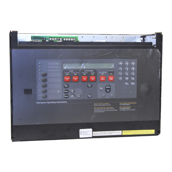
1.2 4100U Basic Operations The Fire Panel display consists of two sections – the Operator Interface (upper section) and the Zone Isolate pushbutton switches & indicators (lower section). Fire detectors are grouped into zones (searchable grouped areas). Zones can be Isolated by pressing the zone‟s isolate pushbutton on the panel –... -
Page 7: Operator Interface Commands
1.3 Operator Interface Commands The table shown below includes some general front panel commands for quickly navigating through system components. In addition output points can be controlled by following the below steps then commanding the point via the On/Off/Auto keys. Manually controlling output points will create a fault on the LCD display, and to clear these faults each manually altered output will need to be set back to its AUTO state. -
Page 8: Resetting 4100 Latched Faults & Rebooting Cpu
1.1.1 Resetting 4100 Latched Faults & Rebooting CPU When fault finding the Simplex® 4100U Fire Detection Panel some IDNet/MAPNet & RUI faults will „latch‟ and not clear without the use of the „System Reset‟ button (described on a previous page). If all else fails, to clear latched faults or some networking issues it may be warranted to use a CPU Reboot otherwise known as a Warm-Start. -
Page 9: Index - Quick View
1.4 Index – Quick view Loop Card Faults Card Missing Failed (Card Inserted) Correct Card Short Circuit Class A Channel Failure Channel Initialization Extra Device Card DIP Switch NOTE - It is vital that the Loop card is in NORMAL status before addressable device fault finding is started. -
Page 10: Loop Card Faults
1.1.2 Loop Card Faults Description: If the Loop card (MAPNET or IDNET) is in an ABNORMAL (FAULT) state, all devices on that loop will be displayed as NORMAL. This NORMAL indication is used to reduce the number of faults when a Loop is not working as all devices would be displayed as NO ANSWER. -
Page 11: Card Missing/Failed
1.1.2.1 Card Missing/Failed Description: The circuit card is not communicating correctly with the panel controller. Possible causes: Card has not been fitted Card is not seated correctly on connector Power down panel, clean connectors and reinsert Card has not been addressed correctly ... -
Page 12: Class 'A' Abnormal
Possible causes: If the fault continually re-appears the loop length maybe too long or too noisy – Contact your local Simplex® branch for assistance Possible bad device causing communication errors Disconnect devices at half way points until the fault clears to locate the faulty device... -
Page 13: Extra Device
1.1.2.3.4 Extra Device Description: A device is located on the addressable loop that is addressed at a location that is not programmed. Possible causes: The panel has identified a device/card at an address that is not in the panel programming. Refer to the Extra Device section of Device Faults (Page 20). -
Page 14: Addressable Device Faults
1.1.3 Addressable Device Faults NOTE - It is vital that the Loop card is in NORMAL status before addressable device fault finding is started. To confirm a Loop card is in NORMAL status: Press the MENU button. Scroll through the options until CARD STATUS is reached. ... -
Page 15: Head Missing
1.1.3.1.2 Head Missing Description: The panel is seeing the base at the displayed address but is not seeing the head (Sensor). Possible causes: Head is not installed. Head is not fully twisted onto the base Detector terminals on the base are loose Faulty Head ... - Page 16 1.1.3.1.3 Wrong Device Description: The panel is getting a response from the displayed address that does not match the device programmed to that address. Possible causes: Incorrect device installed (Relay with T-Sense fitted instead of standard Relay) Incorrect head installed (Photo instead of Heat) Detector head not making good contact with base ...
-
Page 17: Wrong Device
1.1.3.1.4 Bad Answer Description: The panel is getting a response from the displayed address that sometimes does not match the device programmed to that address. Possible causes: Two devices are programmed with the same address. These devices will most likely be two different device types. ... -
Page 18: Extra Device
1.1.3.1.5 Extra Device Description: The panel has identified a device at an address that is not in the panel programming. NOTES: Only one extra device per loop is ever displayed. Fixing one extra device may display a new extra device fault (if present) Extra Device Faults take a longer time to appear and clear than other faults. -
Page 19: Output Abnormal
1. Log in at Level 4 2. Select P214 3. Force Point ON 4. Reset CPU (use button on CPU – refer to Page 7) to clear Simplex® Service Fault 1.1.3.1.8 Detector LED Operation ... -
Page 20: End Of Line Resistors
The highest IDNet device address is 250. The highest MAPNet device address is 127. 1.1.3.1.10 End of Line Resistors For a comprehensive pocket reference guide contact your local Simplex® branch 4090-9001 Supervised IAM 6.8kΩ Current Limited 4.7kΩ & 1.8kΩ... - Page 21 1.1.4 Address Settings for Simplex® Addressable Bases & Devices DIP Switches 5-8 0000 1000 0100 1100 0010 1010 0110 1110 0001 1001 0101 1101 0011 1011 0111 1111 0000 0 1000 1 0100 2 1100 3 0010 4 1010 5...
-
Page 22: 4100-0157A Battery Charger Faults
1.1.5 4100-0157A Battery Charger Faults There are a number of Battery Charger Faults that can arise during the operational lifetime of a panel. You may observe one of the following Faults; Charger 2% out of range Battery Charger Supply incorrect The most common cause is one or possibly both batteries are faulty. - Page 23 4. Measure the voltage on the battery leads. You may have to power down & up again to reset the power supply. If the voltage is correct, power down, re-connect the power & comms harnesses & return the system to normal. 5.
-
Page 24: Positive/Negative Earth Ground Faults
Simplex 4100U – The Simplex 4100U series fire panel has the most advanced earth fault monitoring available to the Simplex Fire Panel Range. The 4100U has the ability to self diagnose and locate the general locale of an earth fault, enabling the saving of much time and effort during diagnosis. There are two main Earth Fault Detection options available for selection in the menu options (accessed via the 4100U fascia), a „Location Search‟... - Page 25 Pre-4100U Series Fire Panels (4100+, 4100A) – The older Simplex 4100 Series Fire panels have the ability to detect Positive/Negative Earth Ground Faults. Unlike the 4100U Series Fire panels, their Power Supplies do not have the option to automatically diagnose on which circuit the fault is located. There are, however, methods which can narrow down the circuits in question.
-
Page 26: 4100 Crash Codes - General Information
2.0 4100 Crash Codes – General Information Page 25 of 60... -
Page 27: 4100 Crash Codes - General Information
CLASS P Crash: Indicates a possible problem in the job software programming. Incompatible job hardware and software can be corrected by reprogramming of the job information. This can occur during installation of new software on a network (Crash Code 78). If it persists, contact your local Simplex® branch. Page 26 of 60... -
Page 28: 4100-Family General Crash Codes Table
2.2 4100-Family General Crash Codes Table Crash Code LCD Display Error Information CRASH_UNEXPECTED Unexpected crash due to possible <CRASH UNEXPECTED> bug in executive software (System – Call Headquarters Technical Support at once! CLASS S CRASH PROM) CRASH_INTERNAL_RAM_BAD <INTERNAL RAM ERROR> Internal RAM error CLASS S CRASH CRASH_EXTERNAL_RAM_BAD... -
Page 29: 4100-Family General Crash Codes Table (Continued)
2.3 4100-Family General Crash Codes Table (continued) LCD Display Error Information Crash Code CRASH_SMPL_CODE_OPCODE Invalid operation code exists <Invalid CODE Operation> Invalid operation code exists in program program CLASS P CRASH This indicates that the system RAM and the CFIG RAM CRASH_RAM_OVERLAP addresses overlap. -
Page 30: Identifying Faults On The Gcc, Ims & Truesite Graphics & Network
29 of 60 of 60 5 of 1 3.0 Identifying Faults on the GCC, IMS & TrueSite Graphics & Network Page 29 of 60... -
Page 31: Identifying Faults On The Graphics - General Instructions
3.1 Identifying Faults on the Graphics – General Instructions The GCC, IMS & TrueSite are all different generations of PC based graphics stations. GCC was for Windows 9.x, IMS for Win2000 & XP, TrueSite is for XP & Vista. All are similar in appearance, functionality & features – the newer versions have extra features Fault buzzer sounds on IMS. -
Page 32: Displayed Fault Format
When an active fault is displayed on the LCD more information about the location of a network fault can be determined by pressing either the „MORE INFO‟ key (4100U) or „FUNCTION‟ (earlier 4100 series panels). On an IMS System, view network information with a „double-click‟ on the current fault to bring up a more detailed information window. -
Page 33: Fault Type
3.2.1 Fault Type Fault Description of most likely cause Head missing Detector Head has been removed from base Pg 14 Output Abnormal Detector output e.g. sounder is faulty Pg 18 Bad Answer (Static) Detector head or base is faulty Pg 16 Bad Answer (Intermittent) Two detectors reporting at the same address Pg 16... -
Page 34: Network Faults
The configurations do not match between at least two nodes. This is due to different revisions of software in the panels & is caused by not programming & downloading to the network correctly. Please Contact your local Simplex Fire Service Provider for Assistance Page 33 of 60... -
Page 35: Identifying F3200 Faults
34 of 60 of 60 5 of 1 4.0 Identifying F3200 Faults Page 34 of 60... -
Page 36: Recall System Faults
4.1 Recall System Faults 4.1.1 Function The Recall System Faults function allows viewing on the LCD the current causes of a "SYSTEM FAULT" indication. It also displays the status of any RZDU (Remote Zone Display Unit) that has an off-normal condition, including those which do not cause System Fault 4.1.2 Operating Sequence For both networked and non-networked systems, from the base display, press:... -
Page 37: List Of System Faults - Non-Networked
4.2 List of System Faults – Non-Networked The complete list of faults which can be displayed by a system fault recall is as follows: Mains fail When mains fail appears in a system fault recall it indicates that mains is currently failed. When mains have failed continuously for 8 hours a system fault may be generated depending on programming. - Page 38 be read correctly at startup. Try isolating and de-isolating something (e.g. bells) to get the controller to retry writing/reading this RAM. EEPROM write fail This fault will occur if a failure occurs when writing to EEPROM database memory during program mode.
- Page 39 RZDU x This displays the current status of any RZDU which has an off-normal condition. Net msg discard This occurs only with network systems. The local system discarded a message that was repeatedly sent to another device on the network that did not acknowledge it. To allow other messages to be sent on the network, the unacknowledged msg was discarded.
-
Page 40: Glossary Of Abbreviations
Glossary of Abbreviations A/C : Air Conditioning ac : Alternating Current AEOL : Active End of Line AHr : Ampere Hour ANC 1 : Ancillary Relay 1 ASE : Alarm Signaling Equipment AZC : Alarm Zone Circuit, or Detection Zone AZF : Alarm Zone Facility, or Group (AS1603.4 terminology) AVF :... - Page 41 T1 : Programmable Timer Number 1 (program abbreviation) Tmnl : Terminal V1 : Programmable Variable Number 1 VA : Volts Amperes VB : Battery Backed Voltage VNB : Non Battery Backed Voltage +VBF : Fused Battery-Backed Voltage +VNBF : Fused Non-Battery-Backed Voltage WS : Warning System Z1 :...
-
Page 42: Identifying Faults On A Qe90
41 of 60 of 60 5 of 1 5.0 Identifying faults on a QE90 Page 41 of 60... -
Page 43: Qe90 Service Isolation Mode - Fault Display
5.1 QE90 Service Isolation Mode – Fault Display To access the fault memory and communications errors facility of a QE90 panel follow these steps; 1. Put the panel into „Isolate‟ [I.e. move key-switch to Isolate position] 2. Press and hold the BGM/PAGING key for 2 seconds until PROGRAM LED (only) is on. 3. -
Page 44: Ecp Versions 2
5.2 ECP versions 2.xx/4.xx/6.xx – System Fault Display 43 of 60 of 60 5 of 1 Page 43 of 60... -
Page 45: Audio Line Fault
5.3 Audio Line Fault 5.3.1 Speaker Line Fault/Amp Fault Check EOL resistor (56k) If ok, swap speaker lines to a different Zone (on amp) Test to see if the fault has followed IF YES – the fault could be in the field (wiring, devices) IF NO –... -
Page 46: Speaker Tapping Adjustments
5.3.3 Speaker Tapping Adjustments Both amplifier types have controls to adjust the power output. NOTE: However in terms of efficiency and battery capacity that it is preferable to reduce the volume by adjusting the speaker taps to a lower setting and leaving the controls turned right up (fully clockwise), rather than by using the volume controls. -
Page 47: Strobe Line Fault
5.4 Strobe Line Fault Check EOL resistor (56k) If ok, swap speaker lines to a different Zone (on amp) Test to see if the fault has followed IF YES – the fault could be in the field (wiring, devices) IF NO – the fault is likely to be in the transformers/amplifiers NOTE: A good way to test where a fault is located within the panel is swapping identical components over and testing to see if the fault follows the device. -
Page 48: Strobe Relay Driver Module And Strobe Light Connection
Strobe Relay Driver Module and Strobe Light Connection 48 of 60 of 60 5.4.2 Cable Sizing 5 of 1 It is inadvisable to use a wire gauge appreciably heavier than the gauges in the table(below) – there may be problems with high inrush currents (which are required to charge the large electrolytic capacitors in some strobe lights) which can weld the relay contacts. -
Page 49: Links And Dip Switches
5.4.3 Links and DIP Switches Each STBM9008 module contains a DIP switch that must be set to the correct address to define the function of the module. Switches SW5-8 set the function of the module and must be set as indicated (a more detailed description of settings included in Table 4). -
Page 50: Stbm9008 Board Installation
Table 4: DIP Switches 5 – 8 – Select MODE for Powered Outputs NOTES: Voltage-free General Purpose relay contacts are unaffected by these DIP switches. Strobe Module outputs (Non-GP) use terminal C as R EFERENCE „A‟ terminals are +ve (active positive signal) for A LERT „B‟... -
Page 51: Bga Or Fip Fault
BGA or FIP Fault A 10V Zener Diode type BZT03-C10 (Normally open input type only) is required as Input End-of-Line. The Zener diode is required to maintain Line Monitoring. The diode must be connected with the cathode (i.e. the end marked with a band) to the positive input (Please see „Termination Points and Example Wiring‟... -
Page 52: Wip Line Fault
5.6 WIP Line Fault The WIPS2000 must connect to a WTRM2000 termination module. The WIPS9004 must connect to a WTRM9007 termination module. Do not swap them over. 52 of 60 of 60 5 of 1 NOTE: WIP Line fault LEDs will flash (whilst un-acknowledged) when a WIP Line fault is detected in its corresponding Zone. -
Page 53: Pa Speech, Spare Speech, Wip Speech, Comms And Spare Comms Cable Faults
5.7 PA Speech, Spare Speech, WIP Speech, Comms and Spare Comms Cable Faults PA Speech Cable Faults, Spare Speech Cable Faults, and WIP Speech Cable Faults refer to the connections between SPIF cards and Secondary ECPs and equipment racks (remote units). As can be seen in the Figure below, the PA Speech, Speech Backup, and WIP Speech terminals will correspond to the respective Fault on the ECP System Fault Display. -
Page 54: Ecp Failures
54 of 60 of 60 5 of 1 If you are having issues with an ECM Network and are unable to diagnose a fault/trouble – please contact your local Simplex® Personnel who will be able to assist. Page 54 of 60... -
Page 55: Ecm Networked System - System Fault Display
5.10 ECM Networked System – System Fault Display Page 55 of 60... -
Page 56: Qe90 Fault Register
5.11 QE90 Fault Register ROUBLE UESTIONS OSSIBLE SOLUTIONS EFERENCE LT0088 sections 24.3 (front Several possibilities: Alert has been turned off; cascade has been panel programming) and I don't get an alert phase in Auto mode, but I can Programming turned off; cascade delays are not set up correctly; system has been 24.4 (serial port select it and it works OK in Manual mode. - Page 57 Yes they will get out of sync. Emux cards cannot be synchronised. You If a zone is large and require two amplifier should try to rearrange the amplifier for the same zone to be in the same Bulletin required. Design circuits, but they happen to be in separate racks rack.
- Page 58 Simplex® T3 strobes only work on EVAC. 1) The Positive should be wired to Terminal B and the Negative should Installation Simplex® T3 Strobes not functioning be wired to Terminal A.
-
Page 59: National Contact Directory
6.0 National Contact Directory Page 59 of 60... -
Page 60: Contact Us
6.1 Contact Us To contact Simplex® Fire Products in Australia please call our National Support Number National Support Phone Number: Branch Office Unit 4, 2-8 South Street RYDALMERE NSW 2116 Sydney Phone: (02) 9638 8280 Fax: (02) 9638 8285 47 Gilby Road...
Need help?
Do you have a question about the 4100 Series and is the answer not in the manual?
Questions and answers
I keep receiving "in control ref P401-P432 Lamp trouble" far right corner says "abnormal"