Table of Contents
Advertisement
Advertisement
Table of Contents
Troubleshooting

Related Manuals for LSIS SV-iG5A Series


Summary of Contents for LSIS SV-iG5A Series
- Page 2 Identifies shock hazards under certain conditions. Particular attention should be directed because dangerous voltage may be present. Keep operating instructions handy for quick reference. Read this manual carefully to maximize the performance of SV-iG5A series inverter and ensure its safe use. WARNING Do not remove the cover while power is applied or the unit is in operation.
- Page 3 Wiring and periodic inspections should be performed at least 10 minutes after disconnecting the input power and after checking the DC link voltage is discharged with a meter (below DC 30V). Otherwise, you may get an electric shock. Operate the switches with dry hands. Otherwise, you may get an electric shock.
- Page 4 OPERATING PRECAUTIONS (1) Handling and installation Handle according to the weight of the product. Do not stack the inverter boxes higher than the number recommended. Install according to instructions specified in this manual. Do not open the cover during delivery. Do not place heavy items on the inverter.
- Page 5 (4) Operation precautions When the Auto restart function is selected, stay away from the equipment as a motor will restart suddenly after an alarm stop. The Stop key on the keypad is valid only when the appropriate function setting has been made.
- Page 6 Important User Information The purpose of this manual is to provide the user with the necessary information to install, program, start up and maintain the SV-iG5A series inverter. To assure successful installation and operation, the material presented must be thoroughly read and understood before proceeding.
-
Page 7: Table Of Contents
Table of Contents CHAPTER 1 - Basic information & precautions ................ 1-1 1.1Important precautions ......................1-1 1.2 Product Details ........................1-2 1.3 Product assembling & disassembling ................... 1-3 CHAPTER 2 - Installation & Wiring .................... 2-1 2.1 Installation precautions ......................2-1 2.2Dimensions .......................... - Page 8 8.4 3-Wire ........................... 8-7 8.5 Dwell operation ........................8-7 8.6 Slip compensation......................... 8-8 8.7 PID control ..........................8-9 8.8 Auto-tuning .......................... 8-13 8.9 Sensorless Vector Control ....................8-14 8.10 Energy-saving operation ....................8-15 8.11 Speed search ........................8-16 8.12 Auto restart try ........................8-18 8.13 Operating sound select (Carrier frequency change) ............
- Page 9 11.4 Operation .......................... 11-3 11.5 Communication protocol (MODBUS-RTU) ................ 11-4 11.6 Communication protocol (LS BUS) ................... 11-4 11.7 Parameter code list <Common area> ................11-8 11.8 Troubleshooting ........................ 11-11 11.9 Miscellaneous ........................11-11 CHAPTER 12 - Troubleshooting & Maintenance............... 12-1 12.1 Protective functions......................
-
Page 10: Chapter 1 - Basic Information & Precautions
CHAPTER 1 - BASIC INFORMATION & PRECAUTIONS 1.1Important precautions Unpacking and Inspect the inverter for any damage that may have occurred during shipping. inspection To verify the inverter unit is the correct one for the application you need, check the inverter type, output ratings on the nameplate and the inverter is intact. -
Page 11: Product Details
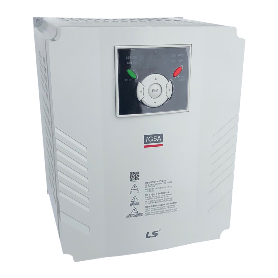
1.2 Product Details Appearance Status LED Display STOP/RESET button RUN button [ENT] button Front cover: Removed when wiring Inverter nameplate Bottom cover: Removed when wiring input power and a motor Inside view after front cover is removed Refer to “1.3 front cover removal” for details. 4-Way button for parameter setting NPN, PNP... -
Page 12: Product Assembling & Disassembling
1.3 Product assembling & disassembling To remove the front cover: Press the both indented sides of the cover lightly and pull up. Press this part lightly and pull it up. To change the inverter fan: Press the both sides of bottom cover lightly and pull out to your side. Press this part and pull out. -
Page 13: Chapter 2 - Installation & Wiring
CHAPTER 2 - INSTALLATION & WIRING 2.1 Installation precautions CAUTION Handle the inverter with care to prevent damage to the plastic components. Do not hold the inverter by the front cover. It may fall off. Install the inverter in a place where it is immune to vibration (5.9 m/s or less). - Page 14 When two or more inverters are installed or a cooling fan is mounted in a panel, the inverters and fan must be installed in proper positions with extreme care to keep the ambient temperature below the permissible range. Installed the inverter using screws or bolts to insure the inverter is firmly fastened. <...
-
Page 15: Dimensions
2.2 Dimensions SV004IG5A-1 SV004iG5A-2 / SV008iG5A-2 SV008IG5A-1 SV004iG5A-4 / SV008iG5A-4 SV015iG5A-2 / SV015iG5A-4... - Page 16 SV015IG5A-1 SV055iG5A-2 / SV075iG5A-2 SV022iG5A-2 / SV037iG5A-2 / SV040iG5A-2 SV055iG5A-4 / SV075iG5A-4 SV022iG5A-4 / SV037iG5A-4 / SV040iG5A-4 Φ...
- Page 17 SV185iG5A-2 / SV220iG5A-2 SV110iG5A-2 /SV150iG5A-2 SV185iG5A-4 / SV220iG5A-4 SV110iG5A-4 / SV150iG5A-4 Φ Φ...
- Page 18 Φ Inverter [kW] [Kg] [mm] [mm] [mm] [mm] [mm] [mm] [mm] SV004IG5A-1 65.5 0.76 SV008IG5A-1 0.75 95.5 1.12 SV015IG5A-1 120.5 1.84 SV004IG5A-2 65.5 0.76 SV008IG5A-2 0.75 65.5 0.77 SV015IG5A-2 95.5 1.12 SV022IG5A-2 120.5 1.84 SV037IG5A-2 120.5 1.89 SV040IG5A-2 120.5 1.89 SV055iG5A-2 3.66 SV075iG5A-2...
-
Page 19: Terminal Wiring (Control I/O)
2.3 Terminal wiring (Control I/O) Description Multi-function open collector output MO Common 24V output MF input terminal FX: Forward run (factory setting) RX: Reverse run Input signal common BX: Emergency stop MF input terminal RST: Trip reset (factory setting) JOG: Jog operation Input signal common Multi-step freq.-Low MF input terminal... - Page 20 * Power terminal wiring (0.4 ~ 7.5kW) 3 Phase AC Power input input (Input rated terminal voltage) Resistor DB resistor connecti terminal Motor connecti Motor terminal ※ AC input of Single Phase Products must be applied in R, T(0.4~1.5kW) Ground terminal * Power terminal wiring (11.0 ~ 22.0kW) R(L1)
-
Page 21: Specifications For Power Terminal Block Wiring
2.4 Specifications for power terminal block wiring 0.4 ~ 0.75kW(Single Phase) 0.4 ~ 1.5kW(Three Phase) 1.5kW(Single Phase) T B1 B2 2.2 ~ 4.0kW(Three Phase) 5.5 ~ 7.5kW(Three Phase) 11.0 ~ 22.0kW(Three Phase) B2 U R,S,T Size U,V,W Size Ground Size Terminal Screw Torque Screw Size... - Page 22 CAUTION Apply the rated torque to terminal screws. Loosen screws can cause of short circuit and malfunction. Tightening the screw too much can damage the terminals and cause short circuit and malfunction. Use copper wires only with 600V, 75℃ ratings for wiring. Make sure the input power is off before wiring.
- Page 23 WARNING Use the Type 3 grounding method (Ground impedance: Below 100Ω) for 230V class inverters. Use the Special Type 3 grounding method (Ground impedance: Below 10Ω) for 460V class inverters. Use the dedicated ground terminal to ground the inverter. Do not use the screw in the case or chassis, etc for grounding.
-
Page 24: Control Terminal Specification
2.5 Control terminal specification Wire size[mm Screw Torque Terminal Description Specification single size [Nm] Stranded wire P1~P8 Multi-function input T/M 1-8 M2.6 Common Terminal M2.6 Power supply for external M2.6 Output voltage: 12V potentiometer Max output current: 10mA Potentiometer:1 ~ 5kohm Input terminal for Voltage M2.6 Max input voltage:... -
Page 25: Pnp/Npn Selection And Connector For Communication Option
2.6 PNP/NPN selection and connector for communication option 1. When using DC 24V inside inverter [NPN] SW S8 DC 24 V SW S8 (inside inverter) 2. When using external DC 24V [PNP] SW S8 DC 24 V DC24V (inside inverter) 2-13... -
Page 27: Chapter 3 - Basic Configuration
CHAPTER 3 - BASIC CONFIGURATION 3.1 Connection of peripheral devices to the inverter The following devices are required to operate the inverter. Proper peripheral devices must be selected and correct connections made to ensure proper operation. An incorrectly applied or installed inverter can result in system malfunction or reduction in product life as well as component damage. -
Page 28: Recommended Mccb
3.2 Recommended MCCB Inverter Inverter MCCB MCCB Capacity Capacity ABS33b,EBs33 GMC-12 ABS33b,EBs33 GMC-12 004iG5A-1 004iG5A-4 ABS33b,EBs33 GMC-12 ABS33b,EBs33 GMC-12 008iG5A-1 008iG5A-4 ABS33b,EBs33 GMC-12 ABS33b,EBs33 GMC-12 015iG5A-1 015iG5A-4 ABS33b,EBs33 GMC-12 ABS33b,EBs33 GMC-22 004iG5A-2 022iG5A-4 ABS33b,EBs33 GMC-12 ABS33b,EBs33 GMC-22 008iG5A-2 037iG5A-4 ABS33b,EBs33 GMC-12 ABS33b,EBs33 GMC-22... -
Page 29: Recommendable Fuse, Reactors
3.3 Recommendable Fuse, Reactors AC Input fuse [External Fuse] Inverter Capacity AC Reactor DC Reactor Current Voltage 004iG5A-1 10 A 500 V 4.20 mH, 3.5A 008iG5A-1 10 A 500 V 2.13 mH, 5.7A 015iG5A-1 15 A 500 V 1.20 mH, 10A 004iG5A-2 10 A 500 V... -
Page 31: Chapter 4 - Programming Keypad & Basic Operation
CHAPTER 4 - PROGRAMMING KEYPAD & BASIC OPERATION 4.1 Keypad features Display SET/RUN LED FWD/REV LED 7 Segment LED STOP/RESET Up/Down Left/Right Enter [ENT] Display Lit during forward run Blinks when a fault occurs Lit during reverse run Lit during Operation Lit during parameter setting 7 segment Displays operation status and parameter information... -
Page 32: Alpha-Numeric View On The Led Keypad
4.2 Alpha-numeric view on the LED keypad... -
Page 33: Moving To Other Groups
4.3 Moving to other groups There are 4 different parameter groups in SV- iG5A series as shown below. Drive group FU group 1 FU group 2 I/O group Drive group Basic parameters necessary for the inverter to run. Parameters such as Target frequency, Accel/Decel time settable. Function group 1 Basic function parameters to adjust output frequency and voltage. - Page 34 How to move to other groups at the 1st code of each group -. The 1 code in Drive group “0.00” will be displayed when AC input power is applied. -. Press the right arrow ( ) key once to go to Function group 1. -.
-
Page 35: How To Change The Codes In A Group
4.4 How to change the codes in a group Code change in Drive group -. In the 1 code in Drive group “0.00”, press the Up ( ) key once. -. The 2 code in Drive group “ACC” is displayed. -. - Page 36 Navigating codes in a group When moving from F 1 to F 15 in Function group 1 -. In F 1, continue pressing the Up ( ) key until F15 is displayed. -. Moving to F15 has been complete. ♣ The same applies to Function group 2 and I/O group.
-
Page 37: Parameter Setting
4.5 Parameter setting Changing parameter values in Drive Group When changing ACC time from 5.0 sec to 16.0 sec Drive group -. In the first code “0.00”, press the Up ( ) key once to go to the second code. -. - Page 38 Frequency setting When changing run frequency to 30.05 Hz in Drive group Drive group -. In “0.00”, press the Ent ( ) key once. -. The second decimal 0 becomes active. -. Press the UP ( ) key until 5 is displayed. -.
- Page 39 Changing parameter value in Input/Output group When changing the parameter value of F28 from 2 to 5 FU group 1 -. In F0, press the Ent ( ) key once. -. Check the present code number. -. Increase the value to 8 by pressing the Up ( ) key. -.
-
Page 40: Monitoring Of Operation Status
4.6 Monitoring of operation status Output current display Monitoring output current in Drive group Drive group -. In [0.0], continue pressing the Up ( ) or Down ( ) key until [CUr] is displayed. -. Monitoring output current is provided in this parameter. -. - Page 41 Fault display How to monitor fault condition in Drive group During Over- Accel current trip Current Frequency STOP Drive group RESET -. This message appears when an Overcurrent fault occurs. -. Press the Enter ( ) key or UP/Down key once. -.
- Page 42 Parameter initialize How to initialize parameters of all four groups in H93 FU group 2 -. In H0, press the Enter ( ) key once. -. Code number of H0 is displayed. -. Increase the value to 3 by pressing the Up ( ) key. -.
-
Page 43: Frequency Setting And Basic Operation
4.7 Frequency Setting and Basic Operation ☞ Caution : The following instructions are given based on the fact that all parameters are set to factory defaults. Results could be different if parameter values are changed. In this case, initialize parameter values (see page 10-21) back to factory defaults and follow the instructions below. Frequency Setting via keypad &... - Page 44 Frequency Setting via potentiometer & operating via terminals -. Apply AC input power to the inverter. -. When 0.00 appears Press the Up ( ) key four times. -. Frq is displayed. Frequency setting mode is selectable. -. Press the Ent ( ) key once. -.
- Page 45 Frequency setting via potentiometer & operating via the Run key -. Apply AC input power to the inverter. -. When 0.00 is displayed, press the Up ( ) key three times. -. “drv” is displayed. Operating method is selectable. -. Press the Ent ( ) key. -.
-
Page 46: Chapter 5 - Function List
CHAPTER 5 - FUNCTION LIST Drive Group Address Min/M Adj. Parameter Factory Description during Page display communi name defaults range cation 0.00 A100 [Frequency This parameter sets the frequency that the 0.00 command] inverter is commanded to output. [Hz] During Stop: Frequency Command During Run: Output Frequency During Multi-step operation: Multi-step frequency 0. - Page 47 Drive Group Address Min/M Adj. Parameter Factory Description during Page display communi name defaults range cation Output power Torque A10C [Fault Displays the types of faults, frequency and Display] operating status at the time of the fault A10D [Direction F, r Sets the direction of motor rotation when drv - of motor [Drive mode] is set to either 0 or 1.
- Page 48 Function group 1 Address Adj. Paramet Min/Max Factory Description during Page display communi er name range defaults cation A200 [Jump 0 ~ 71 Sets the parameter code number to jump. code] [Forwar 0 ~ 2 7-10 Fwd and rev run enable Forward run disable A201 Reverse...
- Page 49 Function group 1 Address Adj. Paramete Min/Max Factory Description during Page display communi r name range defaults cation A215 [Max 40 ~ 400 This parameter sets the highest frequency 60.00 7-21 frequency [Hz] the inverter can output. It is frequency reference for Accel/Decel (See H70) Caution Any frequency cannot be set above Max...
- Page 50 Function group 1 Address Adj. Parameter Min/Max Factory Description during Page display commu name range defaults nication A21E [V/F 0 ~ 2 {Linear} 7-17 pattern] {Square} 7-17 {User V/F} 7-18 A21F [User V/F 0 ~ 400 It is used only when V/F pattern is set to 15.00 7-18 frequency...
- Page 51 Function group 1 Address Adj. Parameter Min/Max Factory Description during Page display communic name range defaults ation A233 [Electronic 50 ~ 200 This parameter sets max current capable of 10-1 thermal flowing to the motor continuously for 1 minute. level for 1 The set value is the percentage of H33 –...
- Page 52 Function group 1 Address Adj. Paramete Min/Max Factory Description during Page display commun r name range defaults ication 0 ~ 7 This parameter stops accelerating during 10-3 A23B [Stall acceleration, decelerating during constant preventio speed run and stops decelerating during n select] deceleration.
- Page 53 Function group 1 Address Adj. Parameter Min/Max Factory Description during Page display commun name range defaults ication A242 [Up-down 0~400[ In case of choosing F65 as a 1 or 2, it means 0.00 step increase or decrease of frequency according frequency] to up-down input A246...
- Page 54 Function group 2 Address Adj. Parameter Min/Max Factory Description during Page display commu name range defaults nication A300 [Jump 0~95 Sets the code number to jump. code] A301 [Fault Stores information on the types of faults, history 1] the frequency, the current and the Accel/Decel condition at the time of fault.
- Page 55 Function group 2 Adj. Address for Parameter Min/Max Factory Description during Page display communication name range defaults A311 [S-Curve 1~100 7-15 Set the speed reference value to form a accel/decel curve at the start during accel/decel. If it is start side] set higher, linear zone gets smaller.
- Page 56 Function group 2 Address Factor Adj. Paramete Min/Max Description during Page display communic r name range default ation A316 8-17 1. H20- [Power Restart Operati after on after accel fault start] instant power failure Bit 3 Bit 2 Bit 1 Bit 0 A317 [Current...
- Page 57 Function group 2 Address Parameter Min/Max Factory Adj. Description Page display communi name range defaults during run cation A31B [Auto Restart 0~60 [sec] This parameter sets the time 8-20 time] between restart tries. A31E [Motor type 0.2~ 22.0 0.2kW 8-16 select] 22.0 22.0kW...
- Page 58 Function group 2 Address Adj. Paramet Min/Max Factory Description during Page display communi er name range defaults cation A327 [Carrier 1 ~ 15 This parameter affects the audible sound 8-21 frequen [kHz] of the motor, noise emission from the inverter, inverter temp, and leakage select] current.
- Page 59 Address Adj. Paramet Min/Max Factory Description during Page display communi er name range defaults cation A335 [Differen 0 ~ 30.0 tial time [sec] for PID controlle r (D gain)] A336 [PID Selects PID control mode 8-10 control Normal PID control mode Process PID control select]...
- Page 60 Function group 2 Address Adj. Parameter Min/Max Factory Description during Page display communi name range defaults cation A337 [PID 0.1 ~ This parameter limits the amount of the 60.00 8-10 output output frequency through the PID control. frequency [Hz] The value is settable within the range of high limit] F21 –...
- Page 61 Address Adj. Parameter Min/Max Factory Description during Page display communi name range defaults cation A346 [Frequenc 0 ~ 1 Based on Max freq (F21) 7-12 Based on Delta freq. Reference Accel/Dec A347 [Accel/De 0 ~ 2 Settable unit: 0.01 second. 7-13 cel time scale]...
- Page 62 A34D [Cooling 0 ~ 1 Always ON 8-30 control] Keeps ON when its temp is higher than inverter protection limit temp. Activated only during operation when its temp is below that of inverter protection limit. A34E [Operating 0 ~ 1 8-31 Continuous operation...
- Page 63 A35C [Paramete 0 ~ 1 Copy the parameters from remote loader r write] and save them into inverter. A35D [Paramete 0 ~ 5 This parameter is used to initialize 8-32 r initialize] parameters back to the factory default value. All parameter groups are initialized to factory default value.
- Page 64 Input/output group Address Adj. Parameter Min/Max Factory Description during Page display communi name range defaults cation 0 ~ 87 Sets the code number to jump. A400 [Jump code] A402 [NV input 0 ~ -10 Sets the minimum voltage of the NV (- 0.00 Min voltage] 10V~0V) input.
- Page 65 Address Adj. Parameter Min/Max Factory Description during Page display communi name range defaults cation A413 [Multi- Jog operation command function input Multi-Step freq – Low terminal P3 define] A414 [Multi- Multi-Step freq – Mid function Multi-Step freq – High input terminal P4 define] A415...
- Page 66 Input/output group Address Adj. Parameter Min/Max Factory Description during Page display communic name range default ation A419 [Input terminal status display] A41A [Output BIT1 BIT0 terminal status display] A41B [Filtering 1 ~ 15 If the value is set higher, the time responsiveness of the Input terminal is constant...
- Page 67 Address Adj. Parameter Min/Max Factory Description during Page display communic name range default ation A42A [Multi- Accel time A42B [Multi- Decel time 5] A42C [Multi- Accel time A42D [Multi- Decel time 6] A42E [Multi- Accel time A42F [Multi- Decel time 7] A432 [Analog 0 ~ 3...
- Page 68 Address Adj. Parameter Min/Max Factory Description during Page display communic name range default ation Low voltage trip (Lvt) Inverter Overheat (OHt) Command loss During Run 9-11 During Stop During constant run During speed searching Wait time for run signal input Multi-function relay select Warning for cooling fan trip Brake signal select...
- Page 69 Address Adj. Paramet Min/Max Factory Description during Page display commun er name range defaults ication A438 [Fault 0 ~ 7 When When the When the relay setting the trip other low voltage output] H26– than low trip occurs [Number of voltage trip auto occurs...
- Page 70 A440 [Commu 2 ~ 100 Frame communication time nication [ms] time setting] A441 [Parity/st When protocol set, op bit communication format can be set. setting] Parity: None, Stop Bit: 1 Parity: None, Stop Bit: 2 Parity: Even, Stop Bit: 1 Parity: Odd, Stop Bit: 1 A442 [Read...
- Page 71 A44F [Write address register A450 [Write address register A451 [Write address register A452 [Brake 0~180 Sets current level to open the brake. 50.0 8-26 open It is set according to H33’s (motor rated current] current) size A453 [Brake 0~10 Sets Brake open delay time. 1.00 open delay...
-
Page 72: Chapter 6 - Control Block Diagram
CHAPTER 6 - CONTROL BLOCK DIAGRAM... -
Page 73: Frequency Setting
6.1 Frequency setting... -
Page 75: Drive Command Setting
6.2 Drive command setting... -
Page 76: Accel/Decel Setting And V/F Control
6.3 Accel/Decel setting and V/F control... -
Page 77: Chapter 7 - Basic Functions
CHAPTER 7 - BASIC FUNCTIONS 7.1 Frequency mode Keypad Frequency setting 1 Group Code Parameter Name Setting Range Initial Unit Drive group 0.00 [Frequency Command] 0 ~ 400 0.00 0 ~ 8 [Frequency mode] Set Frq – [Frequency mode] to 0 {Frequency setting via Keypad 1}. Set the desired frequency in 0.00 and press the Prog/Ent ( ) key to enter the value into memory. - Page 78 Frequency setting via –10 ~ +10[V] input Group Code Parameter Name Setting Range Initial Unit Drive group 0.00 [Frequency Command] 0 ~400 0.00 0 ~ 8 [Frequency Mode] I/O group [NV input minimum voltage] 0 ~ -10 [Frequency corresponding to I2] 0 ~ 400 0.00 [NV input max voltage]...
- Page 79 I6 ~ I10: Setting input range and corresponding frequency to 0 ~ +10V V1 input voltage Ex) when minimum (+) input voltage is 2V with corresponding frequency 10Hz and Max voltage is 8V with run freq. Set freq. 50Hz I 10 10Hz V1 input Frequency setting via 0 ~ 10 [V] input or Terminal Potentiometer...
- Page 80 Frequency setting via 0 ~ 20 [mA] input Group Code Parameter Name Setting Range Initial Unit Drive 0.00 [Frequency Command] 0 ~400 0.00 group 0 ~ 8 [Frequency Mode] [Filter time constant for I input] 0 ~ 9999 group [I input minimum current] 0 ~ 20 [Frequency corresponding to I12] - 0 ~ 400...
- Page 81 Group Code Parameter Name Setting Unit I/O group [NV input Min voltage] [Frequency corresponding to I 2] 0.00 [NV input Max voltage] 10.00 [Frequency corresponding to I 4] 5.00 [V1 input Min voltage] [Frequency corresponding to I 7] 0.00 [V1 input max voltage] [Frequency corresponding to I 9] 5.00 [I input minimum current]...
- Page 82 Frequency setting via Digital Volume (up-down) Group Code Parameter Name Setting Range Initial Unit Drive [Frequency Command] 0 ~400 0.00 group 0 ~ 8 [Frequency Mode] Select 7 in Frq code of Drive group. Related code: I 59, I 60, I 61 Refer to Chapter 13.
-
Page 83: Multi-Step Frequency Setting
7.2 Multi-Step Frequency setting Group Code Parameter Name Setting Range Initial Unit Drive group [Frequency Command] 0 ~ 400 0.00 [Frequency Mode] 0 ~ 8 [Multi-Step frequency 1] 0 ~ 400 10.00 [Multi-Step frequency 2] 20.00 [Multi-Step frequency 3] 30.00 0 ~ 24 [Multi-function input I/O group... -
Page 84: Operating Command Setting Method
7.3 Operating command setting method Operation via keypad RUN key and STOP/RST key Group Code Parameter Name Setting Range Initial Unit Drive group 0 ~ 3 [Drive mode] [Direction of motor rotation F, r select] Set drv – [Drive mode] to 0. Acceleration is started upon pressing the Run key while operating frequency is set. - Page 85 Operating command via FX, RX terminal 2 Group Code Parameter Name Setting Range Initial Unit Drive group 0 ~ 3 [Drive mode] [Multi-function input I/O group 0 ~ 27 terminal P1 define] [Multi-function input 0 ~ 27 terminal P2 define] Set the drv to 2.
- Page 86 Rotating direction select via –10 ~ +10[V] input of V1 terminal Group Code Parameter Name Setting Range Initial Unit Drive group 0 ~ 8 [Frequency setting] [Drive mode] 0 ~ 3 Set frq to 2. Inverter is operating as the table below regardless of Drive mode setting. FWD RUN Command REV RUN Command 0 ~ +10 [V]...
- Page 87 Power On Start select Group Code Parameter Name Setting Range Initial Unit Drive group 0 ~ 3 [Drive mode] 1, 2 Function group 2 0 ~ 1 [Power On Start select] Set H20 to 1. When AC input power is applied to the inverter with drv set to 1 or 2 {Run via control terminal} ON, motor starts acceleration.
-
Page 88: Accel/Decel Time And Pattern Setting
Frequency Reset command When H21 is 0 When H21 is 1 7.4 Accel/Decel time and pattern setting Accel/Decel time setting based on Max frequency Group Code Parameter Name Setting Range Initial Unit Drive group 0 ~ 6000 [Accel time] 0 ~ 6000 10.0 [Decel time] Function group1... - Page 89 More precise time unit can be set corresponding to load characteristics as shown below. In SV-iG5A, number display is available up to 5. Therefore, if time unit is set to 0.01 sec, Max Accel/Decel time would be 600.00 sec. Code Name Setting range Description...
- Page 90 Multi-Accel/Decel time setting via Multi-function terminals Group Code Parameter Name Range Initial Unit Drive [Accel time] group 6000 [Decel time] 10.0 6000 0 ~ 27 [Multi-function input terminal P1 define] group [Multi-function input terminal P12 define] [Multi-function input terminal P3 define] [Multi-function input terminal P4 define]...
- Page 91 Accel/Decel pattern setting Group Code Parameter Name Setting range Initial Unit Function Linear [Accel pattern] group 1 S-curve [Decel pattern] Function [S-Curve Accel/Decel start group 2 side] [S-Curve Accel/Decel end side] Accel/Decel pattern is settable at F2 and F3. Linear: This is a general pattern for constant torque applications. S-curve: This curve allows the motor to accelerate and decelerate smoothly.
- Page 92 Note that setting Frequency Ref. for Accel/decel (H70) is set to Max Freq and target freq is set below Max freq. the shape of S-curve may be distorted. Accel/decel Ref Freq CAUTION If Target Frequency is Target Freq below Max Frequency, the waveform will be shown with the top portion cut out.
-
Page 93: V/F Control
7.5 V/F control Linear V/F pattern operation Group Code Parameter Name Setting Range Initial Unit [Base frequency] Function group 1 30 ~ 400 60.00 [Start frequency] 0.1 ~ 10.0 0.50 0 ~ 2 [V/F pattern] Function group 2 [Control mode select] 0 ~ 3 Set F30 to 0 {Linear}. - Page 94 User V/F pattern operation Group Code Parameter Name Setting Range Initial Unit Function group 1 0 ~ 2 [V/F pattern] [User V/F frequency 1] 0 ~ 400 15.00 [User V/F voltage 4] 0 ~ 100 Select F30 to 2 {User V/F}. User can adjust the Volt/Frequency ratio according to V/F pattern of specialized motors and load characteristics.
- Page 95 Manual torque boost Group Code Parameter Name Setting Range Initial Unit Function 0 ~ 1 [Torque Boost select] group 1 0 ~ 15 [Torque boost in forward direction] [Torque boost in reverse direction] Set F27 to 0 {Manual torque boost}. The values of [Torque boost in forward/reverse direction] are set separately in F28 and F29.
-
Page 96: Stop Method Select
7.6 Stop method select Decel to stop Group Code Parameter Name Setting Range Initial Unit Function group 1 0 ~ 3 [Stop mode select] Select 0 {decel to stop} in F4 code. Motor decelerates to 0 Hz and stops during the setting time. Freq. -
Page 97: Frequency Limit
7.7 Frequency limit Frequency limit using Max Frequency and Start Frequency Group Code Parameter Name Setting Range Initial Unit Function 0 ~ 400 60.00 [Max frequency] group 1 0.1 ~ 10 0.50 [Start frequency] Max Frequency: Frequency highest limit. Any frequency cannot be set above [Max frequency] except for F22 [Base frequency]. - Page 98 Skip frequency Group Code Parameter Name Setting Range Initial Unit Function 0 ~ 1 [Skip frequency select] group 2 [Skip frequency low limit 1] - 0.1 ~ 400 10.00 [Skip frequency low limit 3] - 0.1 ~ 400 35.00 Set H10 to 1. Run frequency setting is not available within the skip frequency range of H11-H16.
-
Page 99: Chapter 8 - Advanced Functions
CHAPTER 8 - ADVANCED FUNCTIONS 8.1 DC brake Stopping motor by DC brake Group Display Parameter Name Setting Range Default Unit Function 0 ~ 3 [Stop mode select] group 1 [DC Brake start frequency] 0.1 ~ 60 5.00 [DC Brake wait time] 0 ~ 60 [DC Brake voltage] 0 ~ 200... - Page 100 Starting DC brake Group Display Parameter Name Setting Range Default Unit Function 0 ~ 200 [DC Brake start voltage] group 1 0 ~ 60 [DC Brake start time] F12: It sets the level as a percent of H33 – [Motor rated current]. F13: Motor accelerates after DC voltage is applied for the set time.
-
Page 101: Jog Operation
8.2 Jog operation Terminal jog operation Group Display Parameter Name Setting Range Default Unit Function 0 ~ 400 10.00 [Jog frequency] group 1 [Multi-function input 0 ~ 25 group terminal P5 define] Set the desired jog frequency in F20. Select a terminal from P1 - P8 to use for this setting. If P5 is set for Jog operation, set I21 to 4 {Jog}. -
Page 102: Up-Down Drive
FX : I 17 = 0 JOG : I23=26 8.3 UP-DOWN Drive Up-down storage function Group Display Parameter Name Setting Range Default Unit Drive [Frequency setting method] group [Multi-function input terminal P1 define] [Multi-function input 0 ~ 27 terminal P6 define] group [Multi-function input terminal P7define]... - Page 103 Up-down mode select Group Display Parameter Name Setting Range Default Unit Drive [Frequency setting method] group [Multi-function input terminal P1 define] 0 ~ 27 [Multi-function input group terminal P7define] [Multi-function input terminal P8define] Function [Up-down mode select] group 1 0~400 0.00 [Up-down step frequency] Select 8 in Frq code of drive group...
- Page 104 When F65 is 1: It is increased as many as step frequency set as F66 at the rising edge of multi- function input set as UP and when up-down is defined, it saves frequency at the falling edge. It is decreased as many as step frequency set as F66 at the falling edge of rising edge of multi- function input set as DOWN and when up-down is defined, it saves frequency as the falling edge.
-
Page 105: 3-Wire
8.4 3-Wire Group Display Parameter Name Setting Range Default Unit [Multi-function Input terminal 0 ~ 27 group P1 select] [Multi-function Input terminal P8 select] Select the terminal from P1-P8 for use as 3-Wire operation. If P8 is selected, set I24 to 17 {3-Wire operation}. FX : I17 = 0 Frequency RX : I18 = 1... -
Page 106: Slip Compensation
Dwell freq. Start freq. Dwell time Frequency command 8.6 Slip compensation Group Display Parameter Name Setting Range Default Unit Function [Motor type select] 0.2 ~ 7.5 group 2 [Number of motor poles] 2 ~ 12 [Rated slip frequency] 0 ~ 10 2.33 [Motor rated current] 0.5 ~ 50... -
Page 107: Pid Control
H33: Enter the motor nameplate rated current. H34: Enter the measured current when the motor is running at rated frequency after the load is removed. Enter 50% of the rated motor current when it is difficult to measure the motor no load current. - Page 108 I17~ [Multi-function input terminal 0 ~ 25 group P1-P8 define] Drive 0~400 0.00 [PID reference] group /0~100 /0.0 0~400 0.00 [PID feedback] /0~100 /0.0 In order to control the amount of following water, pressure and temperature, do PID control to inverter output frequency. Select H49 of function group 2 as a 1 (PID drive select).
- Page 109 Normal PID drive (H54=0) PID control diagram Frequency Conversion PID Gain Mult Function Input PID Limit PID Command Select Analog Input Analog Input Scale Filter PID REF PID Output Frequency PID OUT Communi- Keypad Setting 1 cation Keypad Setting 2 V1_2 : 0 ~ 10V I : 0 ~ 20mA Communication...
- Page 110 Process PID drive (H54=1) 1st/2nd Frequency Select KeyPad-1/-2 V1_1(-10~10V) V1_2(0~10V) I(0~20mA) V1_1 + I V1_2 + I PID Gain Communication Mult Function Output Freq. Limit Input PID Command Select PID Limit PID Output PID REF KeyPad-1/-2 Frequency V1_2(0~10V) I(0~20mA) PID OUT1 PID OUT2 Communication PID F/B Select...
-
Page 111: Auto-Tuning
S le e p F re q W a k e u p le v e l P ID R e fe re n c e P ID F e e d b a c k O u tp u t fre q u e n c y R U N c o m m a n d P ID A c tiv e... -
Page 112: Sensorless Vector Control
8.9 Sensorless Vector Control Group Display Parameter Name Setting Range Default Unit Function 0 ~ 3 [Control mode select] group 2 [Motor type select] 0.2 ~ 22.0 [Rated 0 ~ 10 slip frequency] [Motor rated current] 0.5 ~ 150 [Motor No Load Current] 0.1 ~ 20 [Stator resistance (Rs)] Ω... -
Page 113: Energy-Saving Operation
Factory default by motor ratings Input Motor rating Current No-load Rated slip Stator Leakage voltage [kW] rating current freq resistance inductance [Hz] [mH] [Ω] 2.33 14.0 122.00 3.00 6.70 61.00 0.75 2.33 2.46 28.14 2.33 1.13 14.75 2.00 0.869 11.31 12.9 2.33 0.500... -
Page 114: Speed Search
8.11 Speed search Group Display Parameter Name Setting Range Default Unit Function 0 ~ 15 [Speed search select] group 2 [Current level] 80 ~ 200 [Speed search P gain] 0 ~ 9999 [Speed search I gain] [Multi-function output I/O group terminal select] 0 ~ 18 [Multi-function relay select]... - Page 115 terminal (MO) and Multi-function relay output (3ABC). EX) Speed search during Instant Power Failure restart Input voltage Frequency Voltage Current Multi-function output or Relay When the input power is cut off due to instant power failure, the inverter outputs Low voltage trip (LV) to hold the output. When the power is restored, the inverter outputs the frequency before the low voltage trip and the voltage is increased due to PI control.
-
Page 116: Auto Restart Try
8.12 Auto restart try Group Display Parameter Name Setting Range Default Unit Function 0 ~ 10 [Number of Auto Restart try] group 2 [Auto Restart time] 0 ~ 60 This parameter sets the number of times auto restart is activated in H26. It is used to prevent the system down caused by internal protection function activated by the causes such as noise. -
Page 117: Operating Sound Select (Carrier Frequency Change)
8.13 Operating sound select (Carrier frequency change) Group Display Parameter Name Setting Range Default Unit Function 1 ~ 15 [Carrier frequency] group 2 This parameter affects the sound of the inverter during operation. When setting carrier frequency Motor sound reduced high, Inverter heat loss increased Inverter noise increased... - Page 118 Used when an inverter operates 2 motors connected to two different types of the loads. motor operation does not drive 2 motors at the same time. As the figure below, when using two motors with an inverter by exchanging them, select one motor from 2 motors connected.
-
Page 119: Self-Diagnostic Function
8.15 Self-Diagnostic function How to use Self-Diagnostic function Group Display Parameter Name Setting Range Default Unit Function 0 ~ 3 Self-Diagnostic Selection - group 2 Multi-function input 0 ~ 25 I/O group terminal P1 selection Multi-function input terminal P8 selection Select Self-Diagnostic function in H60, Function group 2. -
Page 120: Frequency Setting And
The following table shows the fault type while this function is active. No. Display Fault type Diagnosis Switch above IGBT’s U phase fault Contact LSIS sales UPHF representatives. Switch below IGBT’s U phase fault UPLF Switch above IGBT’s V phase fault vPHF Switch below IGBT’s V phase fault... - Page 121 Selects the self drive in the 2 switching of Frq2 among the followings Frq2 Frequency mode Keypad digital frequency mode1 Digital Keypad digital frequency mode2 V1 terminal setting1: -10 ~ +10V V1 terminal setting2: 0 ~ +10V Analog I terminal: 0 ~ 20mA V1 terminal setting1 + I terminal V1 terminal setting2 + I terminal Setting via RS-485 communication...
-
Page 122: Over Voltage Trip Prevention Deceleration And Power Braking
8.17 Over voltage trip prevention deceleration and Power Braking Group Display Parameter Name Setting Range Default Unit Function Select stop method 0 ~ 3 group 1 F 59 BIT 0: stall prevention under Accel BIT 1: stall prevention 0 ~ 7 under constant speed BIT 2: stall prevention under Decel... - Page 123 Used to control on, off operation of electronic brake of a load system. It only operates when set value of control mode(H 40) is 0 (V/F control). Build sequence after checking set control mode. When brake control is in operation, DC brake and dwell run do not operate when starting up. Brake open Sequence When the electric motor is given instructions to run, the inverter accelerates CW or CCW to the brake open frequency (I 84, I 85).
-
Page 124: Kinetic Energy Buffering
8.19 Kinetic energy buffering Group Display Parameter Name Setting Range Default Unit Function KEB operation select 1 Group 2 KEB operation start 110.0 ~ 140.0 130.0 level KEB operation stop 110.0 ~ 145.0 135.0 level KEB operation gain 1 ~ 20000 1000 Load inertia When power failure occurs in the input power, DC link voltage of the inverter gets low and low... - Page 125 Select 1 and 2 for F70 The center value of analogue input (selected by the set value of I6~I15) as standard, if the input is big it gets (+), if small (-) and gets reflected in the output frequency as the ratio set in F71. Select 3 for F70 OV as standard, if analog input voltage is big, it gets (+), if small (-) and gets reflected in the output frequency as the ratio set in F71.
-
Page 126: Phase Pwm Drive
8.21 2 Phase PWM drive Group Display Parameter Name Setting Range Default Unit Function PWM controlling mode 0 ~ 1 Group 2 0: NORMAL PWM 1: 2 phase PWM Heat loss and leakage current from inverter can be reduced when H48 is set to 1(2 phase PWM) according to the ratio of load. - Page 127 0: continuous operation when cooling fan trip occurs. -. Operation is not stopped regardless of cooling fan trip. -. When I54 or I55 is set to 18 (cooling fan fault alarm), fault alarm signal can be output using Multi-function output terminal or Multi-function relay. CAUTION If operation is continued after cooling fan trip occurs, Overheat trip may happen and protective function be activated.
-
Page 128: Parameter Read/Write
8.24 Parameter read/write Group Display Parameter Name Setting Range Default Unit 0 ~ 1 [Parameter read] Function group 2 0 ~ 1 [Parameter write] Used to read/write Inverter Parameters using remote keypad. CAUTION Take caution when Parameter write (H92) is executed. By doing this, parameters in inverter are cleared and parameters in remote keypad are copied to inverter. -
Page 129: Parameter Initialize / Lock
8.25 Parameter Initialize / Lock Parameter initialize Group Display Parameter Name Range Default Function [Parameter initialize] group 2 4 groups initialize Drive group initialize F 1 group initialize F 2 group initialize I/O group initialize Select the group to be initialized and perform it in H93 code. Press Enter ( ) key after setting in H93. - Page 130 Follow the table below to change the password. (Current PW: 123 -> New PW: 456) Step Note Keypad display Move to H94 code. Press Enter ( ) key. Enter any number (e.g.: 122). Press the Enter ( ) key. 0 is displayed because wrong value was entered.
-
Page 131: Chapter 9 - Monitoring
CHAPTER 9 - MONITORING 9.1 Operating status monitoring Output current Group Display Parameter Name Setting Range Default Unit Drive group CUr [Output current] Inverter output current can be monitored in Cur. Motor RPM Group Display Parameter Name Setting Range Default Unit Drive group rPM [Motor RPM]... - Page 132 User display select Group Display Parameter Name Setting Range Default Unit Drive group vOL [User display select] Function [Monitoring item select] 0 ~ 2 group 2 The selected item in H73- [Monitoring item select] can be monitored in vOL- [User display select.
-
Page 133: Monitoring The I/O Terminal
9.2 Monitoring the I/O terminal Input terminal status monitoring Group Display Parameter Name Setting Range Default Unit [Input terminals status I/O group display] Current input terminal status (ON/Off) can be monitored in I25. The following is displayed when P1, P3, P4 are ON and P2, P5 are OFF. (ON) (OFF) Output terminal status monitoring... -
Page 134: Monitoring Fault Condition
9.3 Monitoring fault condition Monitoring current fault status Group Display Parameter Name Setting Range Default Unit Drive group [Current Fault Display] Fault occurred during operation is displayed in nOn. Up to 3 kinds of faults can be monitored. This parameter gives information on fault types and the operating status at the time of the fault. Refer to Page 4-11 or 9-5 for keypad setting. - Page 135 When the fault condition is reset via the STOP/RST key or multi-function terminal, information displayed in the nOn will be moved to H1. In addition, the previous fault info stored in H1 will be automatically moved to H2. Therefore, the updated fault info will be stored in the H1. When more than 1 fault occurred at the same time, up to 3 types of faults will be stored in one code.
-
Page 136: Analog Output
9.4 Analog Output Group Display Parameter Name Setting Range Default Unit 0 ~ 3 I/O group [Analog output item select] - [Analog output level 10 ~ 200 adjustment] Output item and the level from the AM terminal are selectable and adjustable. I50: The selected item will be output to Analog output terminal (AM). -
Page 137: Multi-Function Output Terminal (Mo) And Relay (3Ac)
9.5 Multi-function output terminal (MO) and Relay (3AC) Group Code Parameter Setting range Initial [Multi-function FDT-1 output terminal FDT-2 select] FDT-3 [Multi-function relay select] FDT-4 FDT-5 Overload {OLt} Inverter Overload {IOLt} Motor stall {STALL} Over voltage trip {OV} Low voltage trip {LV} Inverter overheat {OH} Command loss During run... - Page 138 I56: When 17 {Fault display} is selected in I54 and I55, Multi-function output terminal and relay will be activated with the value in I56. 0: FDT-1 Check whether the output frequency matches the user-setting frequency. Active condition: Absolute value (preset frequency - output frequency) <= Frequency Detection Bandwidth/2 Group Display...
- Page 139 2: FDT-3 Activated when run frequency meets the following condition. Active condition: Absolute value (FDT level - run frequency) <= FDT Bandwidth/2 Group Display Parameter Name Setting Range Default Unit [Detected Frequency I/O group 30.00 level] 0 ~ 400 [Detected Frequency 10.00 Bandwidth] Cannot be set above Max frequency (F21).
- Page 140 4: FDT-5 Activated as B contact contrast to FDT-4. Active condition: Accel time: Run Frequency >= FDT Level Decel time: Run Frequency > (FDT Level – FDT Bandwidth/2) Group Display Parameter Name Setting Range Default Unit [Detected Frequency I/O group 30.00 level] 0 ~ 400...
- Page 141 12: During operation Activated when run command is input and inverter outputs its voltage. Freq. command 13: During stop Activated during stop without active command. Freq. command 14: during constant run Activated during constant speed operation. Freq. command 15: During speed searching Refer to page 8-17.
-
Page 142: Output Terminal Select At Loder Communication Error
9.6 Output terminal select at loder communication error Group Display Parameter Name Setting Range Default Unit [Output terminal select I/O group 0 ~ 3 when communication error with keypad] Select relay output or open collector output when keypad-inverter communication fails. Keypad inverter communication... -
Page 143: Chapter 10 - Protective Functions
CHAPTER 10 - PROTECTIVE FUNCTIONS 10.1 Electronic Thermal Group Code Parameter Range Initial Unit Function [ETH (Electronic thermal) 0 ~ 1 group 1 select] [Electronic thermal level for 1 50 ~ 200 minute] [Electronic thermal level for 50 ~ 150 continuous] [Motor type] 0 ~ 1... -
Page 144: Overload Warning And Trip
Current [%] ETH trip time [sec] 10.2 Overload Warning and trip Overload warning Group Code Parameter Range Initial Unit 30 ~ 150 [Overload warning level] Function group 1 0 ~ 30 [Overload warning time] 0 ~ 19 [Multi-function output terminal select] group [Multi-function relay select] Select one output terminal for this function between MO and 3ABC. -
Page 145: Stall Prevention
Overload trip Group Code Parameter Range Initial Unit Function 0 ~ 1 [Overload trip select] group 1 [Overload trip level] 30 ~ 200 [Overload trip time] 0 ~ 60 Set F56 to 1. Inverter output is turned off when motor is overloaded. Inverter output is turned off when excessive current flows to the motor for F58 –... - Page 146 For example, set F59 to 3 to make stall prevention active during Acceleration and constant run. When stall prevention is executed during acceleration or deceleration, Accel/Decel time may take longer than the user-setting time. When stall prevention is activated during constant run, t1, t2 executed in accordance with the value set in ACC - [Accel time] and dEC - [Decel time].
-
Page 147: Output Phase Loss Protection
10.4 Output phase loss protection Group Code Parameter Range Initial Unit Function [Input/Output phase loss 0 ~ 3 group 2 protection select] Set H19 value to 1. Output phase loss: Inverter output is shut off at the event of more than one phase loss among U, V and W. -
Page 148: Inverter Overload
FX : I17 = 0 Frequency N.O. : I23 = 18 P4(A contact) N.C. : I24 = 19 P5(B contact) command 10.6 Inverter Overload Group Code Parameter Range Initial Unit [Multi-function output terminal select] 0 ~ 19 group [Multi-function relay select] Inverter overload prevention function is activated when the current above inverter rated current flows. -
Page 149: Db Resistor Enable Duty Setting
Ex 1) The inverter determines the freq reference is lost when DRV- Frq is set to 3 (Analog V1 input), I 16 to 1 and analog input signal is less than half the value set in I 7. Ex 2) The inverter determines the freq reference is lost when DRV- Frq is set to 6 (V1+I), I 16 to 2 and V1 input signal is either below the value set in I 7 or I input value is less than the I 12 value. - Page 150 H75: DB resistor ED limit setting No limit Caution Take caution when DB resistor is used over its Watt rating. Fire may result from resistor overheat. When resistor having heat detection sensor is used, sensor output can be used as external trip signal in multi- function input.
-
Page 151: Chapter 11 - Rs485 Communication
11.2 Specification Performance specification Item Specification Communication RS485 method Transmission form Bus method, Multi drop Link System Applicable inverter SV-iG5A series Converter RS232 converter Connectable drives Max 31 Transmission distance Max. 1,200m (Within 700m Recommend) 11-1... -
Page 152: Installation
Hardware specification Item Specification Installation Use S+, S- terminals on control terminal block Power supply Use Insulated power from the inverter power supply Communication specification Item Specification Communication 19,200/9,600/4,800/2,400/1,200 bps selectable speed Control procedure Asynchronous communication system Communication Half duplex system system Character system ASCII (8 bit) -
Page 153: Operation
Computer and inverter connection System configuration RS232/485 Converter Inverter Inverter Inverter - The number of drives to be connected is up to 31 drives. - The specification of length of communication line is max. 1200m. To ensure stable communication, limit the length below 700m. 11.4 Operation Operating steps Check whether the computer and the inverter are connected correctly. -
Page 154: Communication Protocol (Modbus-Rtu)
11.5 Communication protocol (MODBUS-RTU) Use Modbus-RTU protocol (Open protocol). Computer or other hosts can be Master and inverters Slave. Inverter responds to Read/Write command from Master. Supported function code Function code Description 0x03 Read Hold Register 0x04 Read Input Register 0x06 Preset Single Register 0x10... - Page 155 CMD: Capital letter Character ASCII-HEX Command ‘R’ Read ‘W’ Write ‘X’ Request for monitoring ‘Y’ Action for monitoring Data: ASCII-HEX Ex) when data value is 3000: 3000 (dec) → ‘0’ ’B’ ’B’ ’8’h → 30h 42h 42h 38h Error code: ASCII (20h ~ 7Fh) Receive/Send buffer size: Receive= 39 bite, Send=44 bite Monitor register buffer: 8 Word SUM: to check the communication error...
- Page 156 2) Request for Write: Number of Drive No Address address to Data read “01”~ “W” “XXXX” “1” ~ “8” = n “XXXX…” “XX” “1F” 1 byte 2 bytes 1 byte 4 bytes 1 byte n * 4 bytes 2 byte 1 byte Total bite = 12 + n * 4 = Max 44 2.1) Acknowledge response:...
- Page 157 3.2) Negative Acknowledge Response: Drive No Error code “01” ~ “1F” “X” “**” “XX” 1 byte 2 bytes 1 byte 2 bytes 2 bytes 1 byte Total bite = 9 4) Action Request for monitor register: Request for read of address registered by monitor register. Drive No “01”...
-
Page 158: Parameter Code List
11.7 Parameter code list <Common area> <Common area>: Area accessible regardless of inverter models (Note 3) Address Parameter Scale Unit R/W Data value 0: SV-iS3 5:SV-iV5 1: SV-iG 7: SV-iG5 0x0000 Inverter model 2: SV-iV 8: SV-iC5 3: SV-iH 9: SV-iP5 4: SV-iS5 A: SV-iG5A FFFF 0.4kW 0000... - Page 159 Address Parameter Scale Unit R/W Data value 0x000C DC Link voltage See Function List. 0x000D Output power kW R BIT 0: Stop BIT 1: Forward running BIT 2: Reverse running BIT 3: Fault (Trip) BIT 4: Accelerating BIT 5: Decelerating BIT 6: speed arrival BIT 7: DC Braking 0x000E Inverter status...
- Page 160 Address Parameter Scale Unit R/W Data value BIT 4: P5 BIT 5: P6 0x0010 Input terminal status BIT 6: P7 BIT 7: P8 BIT 0~3: Not Used BIT 4: MO (Multi-Output with OC) 0x0011 Output terminal status BIT 5~6: Not Used BIT 7: 3ABC 0x0012 V1 0~3FF...
-
Page 161: Troubleshooting
11.8 Troubleshooting Refer to Troubleshooting when RS-485 communication error occurs. Check points Corrective measures Is the power provided to the converter? Provide electric power to the converter. Are the connections between converter and Refer to converter manual. computer correct? Is Master not polling? Verify the master is polling the inverter. -
Page 162: Chapter 12 - Troubleshooting & Maintenance
CHAPTER 12 - TROUBLESHOOTING & MAINTENANCE 12.1 Protective functions. WARNING When a fault occurs, the cause must be corrected before the fault can be cleared. If protective function keeps active, it could lead to reduction in product life and damage to the equipment. Fault Display and information Keypad Protective... - Page 163 Fault Display and Information Keypad Protective Descriptions display functions Self-diagnostic Displayed when IGBT damage, output phase short, output phase malfunction ground fault or output phase open occurs. Displayed when user-setting parameters fails to be entered into Parameter save memory. error Displayed when an error occurs in the control circuitry of the Inverter inverter.
-
Page 164: Fault Remedy
12.2 Fault remedy Keypad Cause Remedy display Caution When an overcurrent fault occurs, operation must be started after the cause is Overcurrent removed to avoid damage to IGBT inside the inverter. Accel/Decel time is too short compared Increase the Accel/Decel time. to the GD of the load. - Page 165 Fault remedy Keypad Cause Remedy display Decel time is too short compared to the Increase the Decel time. of the load. Regenerative load is at the inverter Use Dynamic Brake Unit. output. Over voltage Check whether line voltage exceeds Line voltage is too high. its rating.
- Page 166 Fault remedy Protective functions & cause Descriptions Contact your local LSIS sales representative. : Parameter save error : Hardware fault : Communication error : Keypad error : NTC error Overload Protection IOLT : IOLT(inverter Overload Trip) protection is activated at 150% of the inverter rated current for 1 minute and greater.
-
Page 167: Precautions For Maintenance And Inspection
Check the voltage between terminal P or P1 and N using a tester before proceeding. SV-iG5A series inverter has ESD (Electrostatic Discharge) sensitive components. Take protective measures against ESD before touching them for inspection or installation. -
Page 168: Chapter 13 - Specifications
CHAPTER 13 - SPECIFICATIONS 13.1 Technical data Input & output ratings: Single Phase 200V Class SV ■■■iG5A –1 ■■ [HP] Max capacity [kW] 0.75 Capacity [kVA] 0.95 FLA [A] Output ratings Max Frequency 400 [Hz] Max Voltage 3Φ 200 ~ 230V Rated Voltage 1Φ... - Page 169 Input & output ratings: Three Phase 400V Class SV ■■■ iG5A – 4 ■■ [HP] Max capacity [kW] 0.75 18.5 Capacity [kVA] 0.95 12.2 18.3 22.9 29.7 34.3 FLA [A] 1.25 Output ratings 400 [Hz] Frequency Max Voltage 3Φ 380 ~ 480V Rated Voltage 3Φ...
- Page 170 Operation Keypad/ Terminal/ Communication option/ Remote keypad Operation mode selectable Analog: 0 ~ 10[V], -10 ~ 10[V], 0 ~ 20[mA] Frequency setting Digital: Keypad Operation features PID, Up-down, 3-wire NPN / PNP selectable (See page 2-13) FWD/REV RUN, Emergency stop, Fault reset, Jog operation, Multi-step Frequency-High, Mid, Low, Multi-step Multi-function terminal Accel/Decel-High, Mid, Low, DC braking at stop, 2...
-
Page 171: Temperature Derating Information
13.2 Temperature Derating Information Load and ambient temperature classified by the Carrier Frequency 100% % of Drive Rated Amps 40℃ Rating 41℃ ~ 50℃ Rating 10 11 12 13 14 15 Carrier Frequency in kHz Caution 1) The above graph is only applied when the inverter is operated in the allowable temperature. Pay attention to the air cooling when the inverter is installed in a panel box, and the inside temperature should be within an allowable temperature range. - Page 172 2) Remote Cable (2M,3M,5M) Remote Cable Model Number Model number Specification 64100001 INV, REMOTE 2M (SV-iG5A) 64100002 INV, REMOTE 3M (SV-iG5A) 64100003 INV, REMOTE 5M (SV-iG5A) Installation 1) Take off the top cover of the I/O board kit and remove the hole cover to connect remote cable on the side.
-
Page 173: Conduit Kit
3) Connect the other side of the remote cable to the remote keypad as shown below. CAUTION Without Parameter Read(H91), Parameter Write(H92) is not available since the Remote memory is empty when the Remote keypad is first used. Do not use the remote cable other than standard LS’. Otherwise, malfunction may occur due to noise input or voltage drop in the keypad. - Page 174 2) SV055IG5A-2, SV055IG5A-4, SV075IG5A-2, SV075IG5A-4 3) SV110IG5A-2, SV110IG5A-4, SV150IG5A-2, SV150IG5A-4, SV185IG5A-2, SV185IG5A-4, SV220IG5A-2, SV220IG5A-4...
-
Page 175: Emc Filter
Conduit Kit Conduit Kit Model Inverter Conduit Kit 1 SV004IG5A-2/4, SV008IG5A-2/4, SV004IG5A-1 Inverter Conduit Kit 2 SV015IG5A-2/4, SV008IG5A-1 SV022IG5A-2/4, SV037IG5A-2/4, SV040IG5A-2/4, Inverter Conduit Kit 3 SV015IG5A-1 Inverter Conduit Kit 4 SV055IG5A-2/4, SV075IG5A-2/4 Inverter Conduit Kit 5 SV110IG5A-2/4, SV150IG5A-2/4 Inverter Conduit Kit 6 SV185IG5A-2/4, SV220IG5A-2/4 13.5 EMC filter (Reserved) -
Page 176: Declaration Of Conformity
DECLARATION OF CONFORMITY Council Directive(s) to which conformity is declared: 2006/95/CE and 2004/108/CE Units are certified for compliance with: EN 61800-3:2004 EN 50178:1997 Type of Equipment: Inverter (Power Conversion Equipment) Model Name: SV - iG5A Series Trade Mark: LS Industrial Systems Co., Ltd. Representative: LS Industrial Systems Co., Ltd. - Page 177 TECHNICAL STANDARDS APPLIED The standards applied in order to comply with the essential requirements of the Directives 2006/95/CE "Electrical material intended to be used with certain limits of voltage" and 2004/108/CE "Electromagnetic Compatibility" are the following ones: • EN 50178 (1997) “Electronic equipment for use in power installations”.
- Page 178 EMI / RFI POWER LINE FILTERS LS inverters, iG5A series RFI FILTERS THE LS RANGE OF POWER LINE FILTERS FF ( Footprint ) - FE ( Standard ) SERIES, HAVE BEEN SPECIFICALLY DESIGNED WITH HIGH FREQUENCY LS INVERTERS. THE USE OF LS FILTERS, WITH THE INSTALLATION ADVICE OVERLEAF HELP TO ENSURE TROUBLE FREE USE ALONG SIDE SENSITIVE DEVICES AND COMPLIANCE TO CONDUCTED EMISSION AND IMMUNITY STANDARS TO EN 50081 ->...
- Page 179 EMI / RFI POWER LINE FILTERS LS inverters, iG5A series series Footprint Filters iG5A DIMENSIONS MOUNTING LEAKAGE OUTPUT INVERTER CODE VOLTAGE WEIGHT CURRENT POWER MOUNT FIG. CURRENT CHOKES SINGLE PHASE (MAX.) FFG5A-M005-(x) 250VAC SV004iG5A-1 0.4kW 175x76.5x40 161x53 1.2Kg. FS – 1 3.5mA SV008iG5A-1 FFG5A-M006-(x)
- Page 181 Warranty Installation Maker LS Industrial Systems Co., Ltd. (Start-up) Date Warranty Model No. SV-iG5A Period Name Customer Address Information Tel. Name Sales Office Address (Distributor) Tel. Warranty period is 12 months after installation or 18 months after manufactured when the installation date is unidentified.
Need help?
Do you have a question about the SV-iG5A Series and is the answer not in the manual?
Questions and answers
what causes a motor to suddenly stop running after initializing
The LSIS SV-iG5A Series motor may suddenly stop running after initializing due to a Low Voltage trip. This can occur if an instant power failure lasts longer than 15 milliseconds or if the output load exceeds the inverter's rating. Additionally, the inverter's DC link voltage can vary based on the output load, which may also contribute to this issue.
This answer is automatically generated