Simplex 4100ES Installation & Maintenance
Fire indicator panel
Hide thumbs
Also See for 4100ES:
- Installation manual (262 pages) ,
- Operator's manual (93 pages) ,
- Owner's manual (90 pages)

Related Manuals for Simplex 4100ES


Summary of Contents for Simplex 4100ES
- Page 1 Fire 4100 ES Fire Indicator Panel Installation & Maintenance Australian Australian Installation & Maintenance Installation Manual Manual LT0350 Iss 1.5...
- Page 2 6,313,744 and 6,426,697. SmartSync horn/strobe control; 6,281,789. Approvals Australian Standard AS 4428.1 ActivFire Listing Number afp1682 Manufacture The 4100ES is a Fire Indicator Panel manufactured for Tyco Fire Protection Products: Tyco Fire Protection Products 47 Gilby Road Mt Waverley VIC 3149...
-
Page 3: Non-Disclosure Agreement
“dongle”. Because this programming facility allows the user to define in detail the operation of the 4100ES System being customised, changes may be made by the user that prevent this installation from meeting statutory requirements. -
Page 4: Model Number & Firmware Revision
This manual applies to product with the following: Model number : 4100ES Firmware revision : 1.02.04 and on Document Document Name : LT0350 4100ES Installation & Maintenance Manual Issue : 1.5 25 Feb, 2015 Amendment Log 14 May, 2004 Issue 1.0.6... -
Page 5: Cautions, Warnings, And Regulatory Information
If damage is apparent, immediately file a claim with the carrier and notify your Simplex product supplier. SAFETY HAZARD - The 4100ES CPU Card includes a lithium battery. There is danger of explosion if the battery is incorrectly replaced. Replace only with the same or equivalent type recommended by the manufacturer. - Page 6 Table of Contents ......................vii List of Figures ......................xv List of Tables ......................xvi Chapter 1 Introduction to the 4100ES Fire Alarm System ....1 Introduction ....................... 1 In this Chapter ......................1 ...
- Page 7 Overview ......................2-16 Placement Guidelines ..................2-16 Installing 4” X 5” Cards ..................2-19 Step 6. Installing LED/Switch Modules into Expansion Bays (4100ES) ....2-21 Overview ......................2-21 The LED/Switch User Interface ................2-21 ...
- Page 8 MINIPLEX System Guidelines (4100ES) ..............3-4 Overview ........................ 3-4 Guidelines ......................3-4 Configuring Cards (4100ES) ..................3-5 Overview ........................ 3-5 CPU Motherboard DIP Switch ................3-5 TIC Configuration ....................3-5 Configuring Other Cards ..................3-5 ...
- Page 9 Configuration ......................5-8 Notes ........................5-8 Warning ......................... 5-8 Specification ......................5-8 Chapter 6 SPS Field Wiring (4100ES) ..........6-1 Introduction ......................6-1 In this Chapter ....................... 6-1 General Field Wiring Guidelines ................6-2 ...
- Page 10 Chapter 7 IDNet Wiring Rules ............7-1 Introduction ......................7-1 In this Chapter ....................... 7-1 IDNet Ports in 4100ES ....................7-2 Overview ........................ 7-2 IDNet Port Characteristics ..................7-2 Wiring to IDNet Devices ..................... 7-3 ...
- Page 11 Australian Panel Format ..................10-3 Overview ......................10-3 Australian / USA Differences ................10-3 4100ES/4100A Differences .................. 10-3 4100ES Fan Control Module ................... 10-4 Overview ......................10-4 Labeling ....................... 10-4 Mounting & Connection ..................10-4 ...
- Page 12 List of Approved Devices ....................1 Compatible Detectors, IDNET ..................4 Compatible Addressable Field Devices, IDNet ............. 5 Appendix F Compatible Batteries ............. 1 Appendix G 4100ES Specifications ..........1 General ........................1 Fuses ........................1 ...
- Page 13 Appendix K List of Spare Parts ............1 Spare Part Order Codes ..................1 Appendix L List of Drawings ............. 1 ...
- Page 14 Figure 2-12. Mixed Module Placement ............... 2-18 Figure 2-13. Slave Card/PDI Connection ..............2-19 Figure 2-14. Installing the Motherboard in a 4100ES Expansion Bay ......2-20 Figure 2-15. LED/Switch Modules ................2-21 Figure 2-16. LED/Switch Controller ................2-21 ...
- Page 15 Figure 9-1. Serial Connection (slower) ................9-2 Figure 9-2. Ethernet Connection (fast) ................9-2 Figure 10-1. Fan Control Module ................. 10-5 Figure A-1 Dip Switch SWx ..................A-1 Figure D-1. Earth Fault Search Example ..............D-8 List of Tables{ XE "List of Tables" } Table 2-1 Master Controller LEDs 1 through 4 ..........
-
Page 16: Chapter 1 Introduction To The 4100Es Fire Alarm System
Chapter 1 Introduction to the 4100ES Fire Alarm System The 4100ES is an expandable fire alarm system that can be used as a standalone system Introduction with one host panel, or as a wide-ranging system with several remote cabinets, with one or more host panels. -
Page 17: Standalone Configuration
System"} If a small building is being expanded, or if other buildings are being constructed in the same general area (as in a campus application), the standalone 4100ES can be expanded into one of the larger systems described later. The standalone 4100ES uses one FIP (one, two, or three bays) containing the following: System Design ... - Page 18 Remote Transponder Units (RTU) remote boxes called transponder cabinets. 4100ES {xe "transponder interface card (TIC): definition"}{xe "MINIPLEX 4100 Fire Alarm System: transponder interface card (TIC)"}Transponder interface cards (TICs), located in RTU cabinets, take the RUI data directly from the CPU motherboard and distribute it to the modules in the RTU cabinet.
- Page 19 "transponder interface card (TIC): RUI and"}{xe "RUI (remote unit interface): about"} Once the RUI line terminates at a remote cabinet, the TIC (4100ES) in that cabinet distributes the CPU’s data to the other modules within the cabinet.
-
Page 20: Network Configuration
The 4100ES can be expanded to become a network system by using network interface Overview cards (NICs). When a NIC is installed into a 4100ES host panel, it is used to connect to other network nodes. Nodes may be other host 4100 panels, or they may be other things such as Graphical Command Centers (GCCs), and Visual Command Centers (VCCs). - Page 21 Physical Bridge Link Physical Bridge Link Physical Bridging (Star Configuration) Figure 1-4. Interconnected Loop Configuration To be used as a network node, a 4100ES panel must contain the following: System Design CPU.{xe "Network 4100 Fire Alarm System: system design"} ...
- Page 22 Remote Unit Interface – 2-wire communications loop used to connect 4100/4100ES master panels with remote transponders. System Power Supply – the main 4100ES power supply and battery charger module. Also includes an IDNet loop, three NAC outputs, and the brigade relay card.
-
Page 24: Chapter 2 Installing 4100Es Fip Components
4100ES cabinets are available in one-, two-, and three-bay sizes. Each can be equipped Introduction with a solid or windowed door. This chapter describes how to mount all types of 4100ES cabinets to a wall, and how to mount system card bays into the cabinets, modules to bays, etc. - Page 25 In a networked system, the FIP can be connected to other FIPs, so that each host panel is a node on the network. In the Australian 4100ES, the SPS is fitted to a bracket behind the hinged 8U door that CPU Bay has the InfoAlarm operator I/F on it.
- Page 26 Introduction to FIPs (4100ES), Continued The 4100ES Master motherboard (see Figure 2-1) that mounts the CPU card is central to Master Motherboard the 4100ES system. {xe "CPU motherboard: about"}{xe "4100U: CPU motherboard"} NETWORK WIRED MEDIA/ RS-232 RUI TERMINAL BLOCK (TB2)
- Page 27 Introduction to FIPs (4100ES), Continued The CPU Card (see Figure 2-2) mounts onto the master motherboard. The CPU card CPU Card contains an Ethernet service port, an LCD user interface connection, and a serial port for a service modem. Figure 2-2. CPU Card (566-719)
- Page 28 Introduction to FIPs (4100ES), Continued The CPU card LEDs indicate Bootloader status during system start up as shown in the CPU Card LEDs table below. Table 2-1. CPU Card LEDs 1 through 4 Status LED4 LED3 LED2 LED1 Condition Bootloader On (0.25s),...
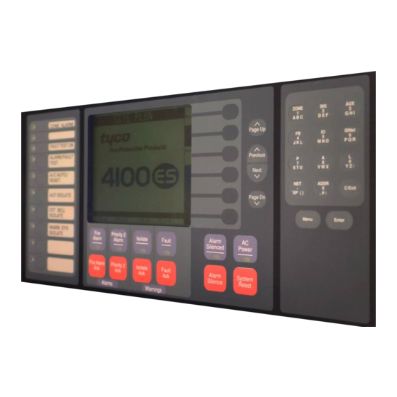
- Page 29 The Operator Interface lets a user operate the panel. It provides alarm, fault, and isolate Operator Interface status alerts, and lets the user review historical logs and perform diagnostics. The 4100ES uses an InfoAlarm graphic display as its user interface. Figure 2-3. InfoAlarm Operator Interface Continued on next page...
- Page 30 Introduction to FIPs (4100ES), Continued In Australian 4100ES FIPs, only one power supply variant (SPS) is currently available, System Power Supply (SPS) and it has hardware and software that are specific to Australia. This unit is used as the main power supply, but additional units may also be fitted directly to a card bay as an expansion supply.
- Page 31 4-inch x 5-inch slave card. If legacy motherboards are used, they must be mounted over the PDI using metal standoffs. Standard cards used in Australian 4100ES, e.g. IDNet, are plugged onto the PDI and only access the 24V Card supply.
- Page 32 180, then re-fitting the equipment. Step 2. Mounting Card Bays to Cabinets (4100ES) FIPs are ordered from the factory with bays and cards fitted as per the panel order Overview spreadsheet.
- Page 33 Rack mount brackets fitted to M6 cage nuts fitted expansion to rack cabinet bay sides Figure 2-6. Bracket and Bay Mounting – earlier style If the cabinet uses the newer bay mounting format (back of cabinet), the ordering code for Rear Mounting Bays an expansion bay is also 4100-KT0446 which will have some surplus parts.
- Page 34 Step 3. Configuring Cards (4100ES) {xe "4100U: card configuration"} The CPU, SPS, and all other modules to be mounted in the FIP cabinets must be Overview configured to operate correctly in the system via their DIP switch and jumper ports. This section describes the hardware configuration for the CPU and SPS, since they will always be used in the CPU bay.
-
Page 35: Step 4. Interconnecting Modules And Bays
Step 3. Configuring Cards (4100ES), Continued P4/P5: The PDI backplane can be configured to draw its power from different sources via PDI Configuration P4 and P5:{xe "power distribution interface (PDI): configuring"}{xe "card configuration: power distribution interface (PDI)"} To draw power from an XPS on the PDI, set jumpers on P4 and P5 to position 2 –... - Page 36 24V Card power and data to each 4”x 5” card. Interconnections Within Expansion Refer to “Step 5: Installing Modules into Expansion Bays (4100ES)” for instructions on Bays mounting 4”x 5” cards to the PDI. Also bear in mind the following variations: ...
- Page 37 Step 4. Interconnecting Modules and Bays, Continued Figure 2-8, below, shows the interconnections between three bays in a host panel. Basic Bay-To-Bay Interconnections (continued) From Previous PDI, SPS or master motherboard 4100 POWER DISTRIBUTION INTERFACE ASSY 566-084 HARNESS 734-008 4100 POWER DISTRIBUTION INTERFACE ASSY 566-084 Figure 2-8.
- Page 38 Step 4. Interconnecting Modules and Bays, Continued Connecting to Motherboards 2. Connect the other end of the harness to the leftmost motherboard in the next bay, (continued) as described below. Make sure to route the wiring on the left side of the bay. ...
- Page 39 Step 5. Installing Modules into Expansion Bays (4100ES) This section contains guidelines and instructions on installing 4”x 5” cards and traditional Overview motherboards into 4100ES card bays. IMPORTANT: This section applies to after market modules for expansion bays only. If you do not need to install any after market modules at all, and if you have followed Steps 1 through 6, you have completed the panel installation and can apply AC power.
- Page 40 Step 5. Installing Modules into Expansion Bays (4100ES), Continued Legacy motherboards can be installed on top of the PDI in expansion bays. The data Placement Guidelines and power that would normally be bussed via the PDI is instead routed across the (continued) boards.
- Page 41 Step 5. Installing Modules into Expansion Bays (4100ES), Continued Placement As shown in the Figure 2.12 below, motherboards can be installed alongside Guidelines 4”x 5” cards, if necessary. (continued) Position Position Block E Slots 7 + 8 Slot 1...
- Page 42 Step 5. Installing Modules into Expansion Bays (4100ES), Continued "mounting: modules to 4100U back boxes"} The power distribution interface (PDI) is mounted to the back of each expansion cabinet. Installing 4” X 5” Cards The PDI contains slots for up to eight 4”x 5” slave cards. Since the PDI carries power and data across the entire bay, it solves most interconnection issues, especially between 4”x 5”...
- Page 43 (FA2255), e.g. ME0426 T-GEN. With the newer rear-mounted expansion bays, this restriction does not apply. METAL STANDOFFS SCREW HOLES PLASTIC STANDOFFS #6 SCREWS SCREW HOLES LOCKWASHERS Figure 2-14. Installing the Motherboard in a 4100ES Expansion Bay 2-20...
- Page 44 The LED/switch controller card mounts behind two LED/switch modules. The LED/switch controller handles up to 64 switches and 64 LEDs on the modules and communicates their status to the 4100ES CPU. When a button is pressed on a module, the LED/Switch...
- Page 45 Step 6. Installing LED/Switch Modules into Expansion Bays (4100ES), Continued If more than 64 LEDs or 64 switches are required, a second controller may be installed on LED/Switch Controller Card, a display door. (continued) LED 1. This LED illuminates if communication loss between the controller and the CPU occurs.
- Page 46 Step 6. Installing LED/Switch Modules into Expansion Bays (4100ES), Continued Refer to the Figure 2.17 below to mount the display cards to the front of the expansion Mounting LED/Switch Modules box. to the Expansion ADDITIONAL LED/SWITCH CONTROLLER #6 UNC NUTS...
- Page 47 Step 6. Installing LED/Switch Modules into Expansion Bays (4100ES), Continued Refer to the figures and instructions below to mount the controller card assembly to the Mounting the Controller Card back of one of the LED/switch cards: Assembly 1. Use four #6-32 Nuts and four #6 Washers to secure the bracket to the inside front of the expansion box.
- Page 48 Step 6. Installing LED/Switch Modules into Expansion Bays (4100ES), Continued Changing Display Card LEDs, (continued) Figure 2-19. Assembling / Disassembling the LED Display Card (pluggable LED version, only) User interface wiring consists of connecting the LED/switch controller card to the...
- Page 49 Step 6. Installing LED/Switch Modules into Expansion Bays (4100ES), Continued The following directions are complete instructions on interconnecting display cards and Wiring Instructions connecting the controller card to a power source: 1. Use Harness 734-008 to connect P2 on the controller card to one of the 4-pin connectors on the PDI.
-
Page 50: Chapter 3 Installing 4100Es Miniplex/Rtu Components
MINIPLEX transponder interface cards (TICs) allow for data and power interconnections Introduction between the 4100ES host panel and remote locations. This chapter describes the transponder installation for 4100ES MINIPLEX/RTU systems. {xe "MINIPLEX 4100 Fire Alarm System: transponder interface card (TIC)"}{xe "transponder interface card (TIC)"}... - Page 51 TIC are not listed for use in Australia. (TICs) Transponder Interface Cards (TICs) transfer data from the 4100ES CPU to the slave cards in the RTU. The Basic TIC is an addressable slave card that contains RUI outputs, an audio riser...
- Page 52 Introduction to MINIPLEX Transponders (4100ES), Continued The Basic TIC has the following LED indicators: LED1. indicates communication loss with the CPU. LED2. Indicates when an RUI ground fault search is active. LED4. Indicates an RUI Style 7 primary trouble. LED5. Indicates an RUI Style 7 secondary trouble.
- Page 53 The master control panel must be a 4100ES Fire Alarm Control Panel. Up to 4 RUI cards in the 4100ES Control Panel can be used for distributing transponder wiring in different directions or for supporting different wiring requirements (such as using a Style 7 (Class A) RUI for serial annunciators).
- Page 54 Configuring Cards (4100ES){xe "transponder interface card (TIC): configuring"}{xe "card configuration: transponder interface card (TIC)"} The TIC and all other cards mounted in the transponder cabinet and attached expansion Overview bays must be configured to operate correctly in the system via their DIP switch and jumper ports.
- Page 55 TIC/Riser Mounting (4100ES){xe "transponder interface card (TIC): mounting"}{xe "mounting: transponder interface card (TIC)"} TICs are mounted like any other 4-inch (102 mm) X 5-inch (127 mm) card. Overview Use the following instructions and Figure 3-2, below, to mount 4”x 5” slave cards to an...
- Page 56 TIC/Motherboard Interconnections (4100ES){xe "transponder interface card (TIC): wiring"}{xe "wiring: transponder interface card (TIC)"} Use Figure 3-3 to connect the TIC to a motherboard in another bay. TMPR SW 24C INPUT SHLD LED4 LED5 POWER/ COMM HARNESS 734-078 4100 LED1 COMM...
- Page 57 RUI Wiring (4100ES) The TIC must be connected to the host panel via RUI cabling. This section explains how Overview to wire the two together, and how to set up a system with multiple transponders connected to the same host panel.
-
Page 58: Chapter 4 Networking
Chapter 4 Networking {xe "Network 4100 Fire Alarm System"} A standalone or MINIPLEX 4100 system becomes a network node when a 4100 Network Introduction Interface Card (NIC) or other compatible network card is installed and connected to another network node. How network cards connect to each other depends on the type of media network cards being used. -
Page 59: Getting Started
1 and a fibreoptic media card connected to port 2). Note: other types of network interfaces are available for special functions, such as single mode fibre modems and TCP/IP bridge cards. Please contact your Simplex representative for more details about these. - Page 60 Introduction to the 4100 Network Interface Card (NIC), Continued Network Interface Card Figure 4-1. 4100-6014 Network Interface Card {xe "network interface card (NIC): LEDS"} The 4100-6014 NIC has the following LEDs: NIC Card LED Indications LED1 (yellow). Illuminates when: The host 4100 requests it to illuminate.
- Page 61 Introduction to the 4100 Network Interface Card (NIC), Continued There are two approved media cards that can be plugged onto the 4100-6014 NIC: NIC Media Cards 4100-6057 Fiber-Optic Media Card (565-261). 4100-6056 Wired Media Card (565-413). {xe "media cards"}{xe "fiber-optic media card"}{xe "wired media card"} Each module is shown below.
-
Page 62: Step 1. Configuring Network Cards
Introduction to the 4100 Network Interface Card (NIC), {xe "wired Continued media card: specifications"}{xe "fiber-optic media card: specifications"}{xe "network interface card: specifications"}{xe "modem media card: specifications"} Requirements and Limitations Table 4-1. 4100 NIC & Media Cards - Electrical and Environmental Specifications Electrical Specifications Network... - Page 63 Step 1. Configuring Network Cards, Continued There are two shunt jumper ports on the NIC card that need to be set: P3 and P4. NIC Card Jumper Settings P3: Determines the NIC data transmission rate, 57.6 kbits/second or 9600 bits/second. ...
-
Page 64: Step 2. Mounting Media Cards To The Nic
Step 2. Mounting Media Cards to the NIC The 4100-6014 Network Interface Card (NIC) uses media cards to connect to other NICs. Overview This section describes how the media cards are mounted onto NICs. NICs connect to each other via the media cards. The types of media cards in the right and Media Card Mounting left ports are determined by the type of wiring that is being used between cards. -
Page 65: Step 3. Mounting Network Cards
Step 3. Mounting Network Cards The 4100 NIC, shown in Figure 4-5 below, inserts into its motherboard as follows: If the 565-274 Master Motherboard is being used, the NIC daughter card is inserted into connector J1. If the 566-227 Master Motherboard or 565-275 Motherboard is used, the NIC daughter card is inserted into connector J2. -
Page 66: Step 4. Wiring Network Cards
Step 4. Wiring Network Cards The nodes in the network now have to be wired together, so that the NIC in one host Overview panel connects to the NIC in the next panel. This section contains guidelines and instructions for NIC wiring. {xe "network interface card (NIC): wiring"}{xe "wiring: network interface card (NIC)"} Refer to the following guidelines whenever field wiring the NICs: Wiring Guidelines... - Page 67 Step 4. Wiring Network Cards, Continued Maximum wiring distances are shown in the Table below and in Appendix J. Wiring Distances Table 4-2. Wiring Distances Media Type Size Data Rate Max Distance 57.6 kbps 7,000 ft (2,130 m) 24 AWG (0.20 mm 9.6 kbps 12,000 ft (3,650 m)
- Page 68 Step 4. Wiring Network Cards, Continued Connectors U1 (transmitter) and U2 (receiver) on the 4100-6057 Fiber-Optic Media Card Fiber-Optic Wiring are used to connect 4100-6014 NICs across parts of a network. {xe "network interface card (NIC): wiring, fiber-optic"}{xe "wiring: fiber-optic media card"}{xe "fiber-optic media card: wiring"} Note: ST connectors with long strain relief boots are to be used with the fibreoptic cable.
- Page 69 Step 4. Wiring Network Cards, Continued The 4190-9010 Coupler (271-012) is used with the Fiber Optic Media Board, revision 4190-9010 Coupler Requirements “C” or higher. Two 4190-9010 Bi-Directional Couplers are required per connection, one at each node. {xe "fiber-optic media card: wire distances"}{xe "fiber-optic media card: coupler requirements"} The 4190-9010 is equipped with type ST connectors.
- Page 70 Step 4. Wiring Network Cards, Continued The illustration below shows coupler wiring.{xe "fiber-optic media card: coupler 4190-9010 Coupler Requirements requirements"}{xe "wiring: coupler for fiber-optic media"} (continued) Figure 4-7. Coupler Wiring Refer to the guidelines and figures in this topic to use wired media cards. Wiring with the Wired Media Card {xe "network interface card (NIC): wiring, with wired media"}{xe "wiring: wired media...
- Page 71 Step 4. Wiring Network Cards, Continued The Table below lists the 4100ES master motherboard connections for the wired media Wiring with the Wired Media Card card. (continued) Table 4-5. 566-227 CPU Motherboard Wired Media Connections Motherboard Port for Media Wired Media Card Connection...
- Page 72 Step 4. Wiring Network Cards, Continued Loop Wiring, mixed Fibre and Cable Figure 4-9 shows an example of loop network cabling using a mixture of fibre optical cable and twisted pair. Note that the left port of each network card is connected to the right port of the next network card regardless of whether the connection is fibre or copper.
- Page 73 4-16...
-
Page 74: Chapter 5 The System Power Supply & Alarm Relay Card
Chapter 5 The System Power Supply & Alarm Relay Card The SPS is introduced in Chapter 2. A picture is shown in Figure 2.4. Introduction This chapter has the current and voltage ratings of the system power supply (SPS) and describes how it is installed and configured by the factory. -
Page 75: Sps Specifications
3.3 A (Default; for 18-110 Ah battery) Notes: AC power must be provided to the 4100ES from a dedicated AC branch circuit. The AC input is supervised. A mains fail fault is generated when the DC voltage drops below 20.3V (nominally 204Vac). - Page 76 SPS Specifications, Continued The bulk supply (rated at 9A max) which feeds 24V Sig, 24V Card, 24V Aux also supplies the SPS Card including the on board IDNet, and the battery charger. The charger is disabled during alarm conditions so as to make the 9A available on the other busses.
-
Page 77: Sps Configuration
SPS Specifications, Continued Additional alarm conditions: Fault relay activated, power fault LED on, IDNet LED on, battery charger off, auxiliary power load = 0 mA, NAC alarm load = 0 mA, IDNet = 35 V Environmental The range of possible temperatures under which the SPS may function are between 0 C Requirements and 50... -
Page 78: Sps Led Indications
R342 Voltage Measurement Calibration Adjust this potentiometer to match the indication of charger voltage on the panel user interface with that on a calibrated voltmeter measuring the charger output. Use the “Card Status” option of the menu. Match the two readings to within 0.05V DC. SPS LED Indications The SPS has the following LED indicators: LEDs... -
Page 79: Troubleshooting An Sps
This message does not appear if there are no configured devices on the IDNet channel. Occurs when the 4100ES is put into a diagnostic mode and finds a device not responding, No Answer/ Bad Answer or responding unreliably. -
Page 80: The Alarm Relay Card
The Alarm Relay Card The Alarm Relay Card mounts on, and is driven by, the SPS. It has 3 relays, each Overview providing one set of voltage-free contacts. The relays are able to be configured under custom control, but the default operation is for system status, i.e. - Page 81 The Alarm Relay Card, Continued The relays have one set of voltage-free contacts (see note below) connected to one pair of Configuration terminals via a header. The two terminals are configured for normally closed or normally open by positioning a jumper on the header. Table 6-3.
-
Page 82: Chapter 6 Sps Field Wiring (4100Es)
Refer to the page number listed in this table for information on a specific topic. In this Chapter Topic See Page # General Field Wiring Guidelines SPS NAC Field Wiring Guidelines Power Supply Wiring Distances Using T-GEN 50 with 4100ES SPS Auxiliary Power Wiring 6-15 SPS Relay Wiring 6-17... -
Page 83: General Field Wiring Guidelines
General Field Wiring Guidelines Make sure these guidelines are accounted for before wiring: General Guidelines All field wires must be 0.75 mm or greater and comply with AS 1670.1 and the wiring code. Conductors must test free of all grounds. ... - Page 84 LCD. The Australian SPS has extra decoupling capacitors fitted to the NAC outputs, and cannot be used to drive the Simplex range of addressable appliances. NACs may be programmed to be normally on and the terminals used as power supply outputs.
-
Page 85: Sps Nac Field Wiring Guidelines
SPS NAC Field Wiring Guidelines, Continued To connect the SPS to reverse-polarity, non-addressable notification appliances using Class A NAC Wiring Class A wiring, read the following instructions and refer to the Figure 6.2 below: {xe "wiring: Class A (NAC)"}{xe "Class A wiring: NACs"}{xe "NACs: wiring (Class A)"} 1. - Page 86 SPS NAC Field Wiring Guidelines, {xe "wiring: Class B (NAC)"}{xe Continued "Class B wiring: NACs"}{xe "NACs: wiring (Class B)"} To connect the NAC output to alarm devices using Class B wiring: Class B NAC Wiring 1. Route wire (between 0.75 mm and 4 mm ) from the B+, B- outputs on TB2 of the SPS to the appropriate inputs on a peripheral notification appliance.
- Page 87 Power Supply Wiring Distances{xe "wiring: distances, Class A (NAC)"}{xe "NACs: wiring distances (Class A)"}{xe "Class A wiring: distances (NAC)"} Before wiring from any type of power supply to notification appliances, check Tables 6-1 Overview and 6-2 for wiring distances. Table 6-1 lists the maximum distances from the NAC terminal block to the last appliance Class A NAC Wiring Table in a Class A configuration, depending on wire gauge and current.
- Page 88 Power Supply Wiring Distances, {xe "wiring: distances, Class B Continued (NAC)"}{xe "NACs: wiring distances (Class B)"}{xe "Class B wiring: distances (NAC)"} Table 6-2 lists the maximum distances from the NAC terminal block to the last appliance Class B NAC Wiring Table in a Class B configuration, depending on wire gauge and current.
- Page 89 AS 1670.1 requires fire alarm warning systems to produce sounds complying with Overview AS 2220 or ISO 8201. One way of meeting this requirement in a 4100ES system is to use a T-GEN 50 tone generator, which is capable of driving up to 50W of load on a 100V speaker line.
- Page 90 The T-GEN 50 should not be powered from a NAC output. T-GEN 50 draws a large in- rush current when it is first turned on, which produces an “SPS Over Current” fault in the system that can only be cleared by pressing the 4100ES System Reset button. This is not acceptable operation.
- Page 91 Figure 6-5 shows the wiring between the T-GEN 50 and the relay module. The detail of the 24V supply is not shown, but the T-GEN 50 0V MUST be common with the 4100ES 0V (this will always be the case when using the AUX POWER supply, as described earlier).
- Page 92 Using T-GEN 50 with 4100ES, Continued These switch and link settings should be used. These apply to T-GEN 50 software T-GEN 50 Setting for version 1.7. Relay Operation Table 6-3. T-GEN 50 Settings for Relay Operation Alert to Evacuate Change-Over Time...
- Page 93 Figure 6-6 shows the wiring between the T-GEN 50 and the NAC terminals. The detail of the 24V supply is not shown, but the T-GEN 50 0V MUST be common with the 4100ES 0V (this will always be the case when using the AUX POWER supply as described earlier).
- Page 94 Using T-GEN 50 with 4100ES, Continued These switch and link settings should be used. These apply to T-GEN 50 software T-GEN 50 Settings for NAC Operation version 1.7. Table 6-6. T-GEN 50 Settings for NAC Operation Alert to Evacuate Change-Over Time...
- Page 95 The control can be fitted to an FP0935 or FP0937 4U Brigade Interface door as used in 4100ES-S1, or fitted to a 4100-1279 blank display module (requires a 9.5mm hole to be drilled in the display module – the ME0460 includes an installation guide with drilling details).
-
Page 96: Sps Auxiliary Power Wiring
SPS Auxiliary Power Wiring The panel, battery-backed, unregulated dc bulk power is available from the SPS via the Overview NAC and the 24V Aux power terminals (1 pair only, as in Figure 6-8). NACs not configured as switched outputs may be configured as auxiliary power point type in the 4100 Programmer. - Page 97 SPS Auxiliary Power Wiring, {xe "auxiliary power: isolators Continued and"}{xe "IDNet power isolator"}{xe "isolators"}{xe "power isolators"} The SPS can connect to auxiliary power appliances via the dedicated auxiliary power tap Wiring (TB3). If more power is needed, any of the unused NAC outputs can be used for auxiliary power.
- Page 98 SPS Relay Wiring{xe "wiring: SPS auxiliary relay"}{xe "system power supply (SPS): wiring, auxiliary relay"}{xe "wiring: auxiliary relay"}{xe "auxiliary relay"} The SPS has one programmable relay, AUX 1, with one set of voltage-free contacts (see Overview below). It also has provision for mounting a 4100-6033 Alarm Relay that has 3 relays, each with one set of normally open (or normally closed) contacts available on a screw terminal block (see Figure 5-1).
- Page 99 SPS Auxiliary Relay Wiring, Continued Figure 6-9 below shows the SPS relays. Relays B+ B- A+ A- B+ B- A+ A- B+ B- A+ A- ALARM RELAY MODULE Dedicated Auxiliary 1 relay terminal block NO C NC TERMINAL BLOCK Figure 6-9. Auxiliary Relay & Alarm Relay Card Relays 6-18...
-
Page 100: Chapter 7 Idnet Wiring Rules
Chapter 7 IDNet Wiring Rules {xe "service port"} The 4100ES supports IDNet ports on several different slave cards. Each IDNet port Introduction provides a connection to a wiring loop of up to 250 addressable detectors and devices. These IDNet ports use Mapnet Protocol and communicate with existing Mapnet detectors/devices plus the new IDNet devices. - Page 101 IDNet Ports in 4100ES There are three 4100ES slave modules with IDNet ports: Overview 4100-9848AU SPS System Power Supply – this supports up to 250 devices in a single loop or string. The IDNet port is not isolated from the system 24V supply.
-
Page 102: Wiring To Idnet Devices
Class B wiring. See Appendix E for a list of compatible devices and their ratings. Use ferrite beads on each pair of wires leaving the 4100ES cabinet. See Guidelines Figure 7-1. See Appendix K for ordering part numbers. - Page 103 Wiring to IDNet Devices, Continued 1. The current allowance per device on the loop is 0.5mA with the LED off, 2mA with Notes the LED on. A maximum of 20 LEDs will be turned on at any time by the IDNet Card, e.g.
- Page 104 Wiring to IDNet Devices, Continued To connect the IDNet card to devices using Class A (loop) wiring, see Figure 7-5 and the Class A Wiring following: 1. Route wire from the IDNet B+, IDNetB- outputs on TB1 of the IDNet card to the appropriate inputs on a peripheral IDNet device.
- Page 105 1. On the IDNet port, connect IDNet B+ to IDNet A+, and IDNet B- to IDNet A-. If this connection is not made, a Class A Fault (open circuit loop) will be registered by the 4100ES. 2. Route wire from the IDNet A+ and IDNet A- outputs of the IDNet port to the first device, then on to the following devices.
- Page 106 Troubleshooting IDNet Faults This section describes the messages that may appear on the 4100 display when using the Overview IDNet card. Fault messages appear in the headings on the left, and possible causes are listed in the text. There is no output voltage from the IDNet power supply. Replace the IDNet card. IDNet Power Monitor Trouble Appears if one or more extra devices (i.e., devices that have not been configured for the...
-
Page 108: Chapter 8 Using Install Mode
Install Mode is a 4100ES facility which is useful during panel installation. Introduction While a 4100ES panel is being installed and commissioned, there will often be periods when many internal modules or external devices are not yet connected, or are not in a normal state for some reason. - Page 109 Adding Devices to Install Mode Adding a Single Devices can be added individually to the Install Mode list. Device to Install Mode NOTE: this requires being logged in at Level 3. Refer to the Operator Manual, if necessary, to do this. The example Fault List in Figure 8-1 shows a fault from a missing slave card in the panel.
- Page 110 Adding Devices to Install Mode, Continued Pressing the <Fault Ack> key will show the Fault List, now with a single entry as shown in Figure 8-3. Figure 8-3. Fault List Now With Only a Single Install Mode Fault Where there are many missing devices, all producing faults, as in Figure 8-4 below, there Adding Multiple Devices to Install are simple ways to quickly add these to the Install Mode list in bulk.
- Page 111 Adding Devices to Install Mode, Continued In the Diagnostic menu screen, scroll down to the Install Mode option as in Figure 8-6. There are many diagnostic options, so using <PgDn> to jump a screen at a time will be faster. Press the <SELE> softkey to select it. Figure 8-6.
- Page 112 Viewing Devices in Install Mode The contents of the Install Mode list can viewed with the VIEW option of the Install Viewing Contents of Install Mode list Mode menu, as in Figure 8-8. See Figures 8-5 and 8-6 for the menu selections to reach this menu.
- Page 113 Removing Devices from Install Mode If you are logged at Level 3, you can remove individual devices from the Install Mode Removing Individual Devices from Install list. Mode Display the Install Mode list as in Figure 8-9, move the highlight to the device you wish to remove, and press the <MORE>...
-
Page 114: Chapter 9 Pc Software Connections
Chapter 9 PC Software Connections The service port on the door with the Operator Interface enables the 4100ES to connect to Introduction PCs running important utilities, such as diagnostics, programming, CPU firmware downloading, and channel monitoring. The recommended connection method is using the Ethernet service port. However, a serial data connection can be used if the Ethernet option is not available for some reason. - Page 115 This mode provides application startup messages, a command line interface to diagnostic commands, and event reporting. This is the default mode when a PC is connected to the 4100ES serial service port (Figure 9 1). The PC must be running terminal emulation software, e.g., Hyperterm. The ES Programmer provides a suitable terminal emulation program for this.
-
Page 116: Chapter 10 Australian Version Specifics
This chapter provides detail on format and components that are specific to the Australian Introduction version 4100ES that complies with AS 4428. Refer to the page number listed in this table for information on a specific topic. In this Chapter... - Page 117 Have some Australian specific components. Limit the number of system components available in the Australian version. The 4100ES Operator Interface does not comply with the AS 4428.1 requirements for an AS 4428 Requirements FF (Firefighter Facility) that uses only an alphanumeric display for alarm zone status indication.
- Page 118 Other cards / modules not used in Australia include the large range of Evacuation products and some modems. {xe "service port: software modes"}{xe "software modes"} Standard 4100 motherboards and cards fit in a 4100ES bay. The following 4100A items 4100ES/4100A Differences however, do not fit: ...
- Page 119 (https://www.tycosafetyproducts-anz.com) as LB0605. This template allows entry of the fan name on a PC for local printing. LED names may also be revised. The Fan Control module mounts to the frame of the 4100ES Expansion bay door, from Mounting &...
- Page 120 Figure 10-1. Fan Control Module 10-5...
-
Page 121: Brigade Interfaces
Brigade Interfaces {xe "service port: software modes"}{xe "software modes"} The Alarm Relay Card is typically used to provide a Brigade Interface. The def{xe Overview "service port: software modes"}{xe "software modes"}ault configuration is for the three relays to operate on Fault (Trouble), Isolate (Supervisory) and Alarm, respectively. The connection drawings for the Centaur ASE, Western Australia AIU and Queensland PPU are included in the appendix. -
Page 122: Chapter 11 Installation Checklist, Commissioning & Maintenance
Chapter 11 Installation Checklist, Commissioning & Maintenance {xe "service port"} When a branch designs a system and orders a 4100ES panel, a “Configuration Sheet” is Introduction prepared. The factory builds the panel to the configuration sheet. This includes fitting, connecting and configuring cards and modules. -
Page 123: Installation Checklist
Installation Checklist The following checklist should be completed by the installer. (Note that all pcbs are Overview electronically tested and adjusted before being fitted to the FIP). CABINET & GENERAL Cabinet colour - Standard Cream Wrinkle (BFF 998 CW) - Other: ____________________________________ Cabinet undamaged (Paint OK) Door aligned correctly Window undamaged and fitted correctly... -
Page 124: Alignment And Adjustment
Alignment & Adjustment All the 4100ES cards and modules are tested and aligned in the factory before being Overview supplied to the customer or fitted to a FIP. The only field adjustment that may be necessary is to set the battery charger voltage. This has been set and should not need re- adjusting. - Page 125 Maintenance The 4100ES system must be kept free from faults and tested on a regular basis to verify that it is operating correctly. The tests required by the standard AS 1851 Maintenance of Fire Protection Equipment are detailed in the 4100ES InfoAlarm Operator’s Manual, LT0568.
- Page 126 Appendix A The Device Configuration DIP Switch {xe "addresses: setting, for 4100U modules"}{xe "card configuration: address setting"} Addressable cards include a bank of eight DIP switches. From left to right (see Figure A- Overview 1, below) these switches are designated as SWx-1 through SWx-8. The function of these switches is as follows: ...
- Page 127 Overview, (continued) Table A-1. Card Addresses Address SW 1-2 SW 1-3 SW 1-4 SW 1-5 SW 1-6 SW 1-7 SW 1-8 Address SW 1-2 SW 1-3 SW 1-4 SW 1-5 SW 1-6 SW 1-7 SW 1-8...
-
Page 128: Appendix B Programming Requirements
This appendix identifies the programming that is required to comply with AS 4428. Introduction It does not provide equations or detail of programming. The separate 4100ES Programming Manual (LT0400) tells how to use the PC-based 4100ES Programmer. Refer to the page number listed in this table for information on a specific topic. -
Page 130: Appendix C Checking System Wiring
Ohm Meter and instructions below. Notes: Ensure that no power is applied to the 4100ES fire alarm panel and that all internal panel wiring is properly connected (terminal blocks, LED/switch module ribbon cables, etc). Use the earth stud in the control panel as the earth connection for all measurements to ground. - Page 131 Appendix C: Checking System Wiring, Continued Table C-1 lists the correct meter readings for indicating appliances and initiating devices. Meter Readings Table C-1. Acceptable Zone and Signal Circuit Meter Readings Circuit Type Meter Reading Class B (spur) Detector Circuit From zone + to zone – (each zone) 3.3k...
-
Page 132: Appendix D Earth Fault Detection
Earth Fault Search is conducted by the FIP. The diagnostic may be activated using either the front panel interface or the Computer Port Protocol (CPP), via a service port. The 4100ES supports two types of Earth Fault Searches: Location Search. Searches all circuits at a location, such as a transponder or the main panel. -
Page 133: General Guidelines
Earth Fault Search detects only one fault at a time. Multiple faults require fixing the first fault and then repeating the search. The 4100ES panel suspends normal operation for the duration of the Earth Fault Search. Location Earth Fault Searches optionally allow exclusion of auxiliary power circuits from the search, so that modules connected to the 24 V auxiliary outputs can remain in operation during the search. -
Page 134: Earth Fault Searching From The Front Panel
Access Level Selection refer to the InfoAlarm Operator Manual supplied with the 4100ES, for the detail of how to log in at a higher level than 1. You can now open the diagnostic menu as described in the next topic. - Page 135 Earth Fault Searching from the Front Panel, Continued The search types are described below. Starting the Earth Fault Search, Continued If you select the Location Search menu item, a list of searchable cards is presented. Use Location Search the Next and Previous buttons to scroll through the list, if necessary. Having selected a power supply to search, the Aux Power Select option comes up.
- Page 136 Earth Fault Searching from the Front Panel, Continued Now you are prompted to start the search. NOTE: The FIP suspends normal operation for the duration of the search. Press the Enter button to start the search. Skip ahead to the "Completing the Search" topic. If you select the IDNet Channel Search menu item, a list of available IDNet channels to IDNet Channel Search...
- Page 137 Earth Fault Searching from the Front Panel, Continued This option simply displays the last Earth Fault Search result. If there has been no search Last Search Result since the last system startup, or if the last search was aborted, the panel displays "RESULT NOT AVAILABLE."...
-
Page 138: Search Results
Search Results There are several types of results that can display at the end of an Earth Fault Search. This Overview section covers all types of results. IMPORTANT: Once you have been directed to an earth ground fault and corrected it, it is recommended that you restart the system (warm- or cold- start). - Page 139 Search Results, Continued If the message reads FAULT NOT FOUND (for a Location Earth Fault Search) or Fault Not Found FAULT CLEAR FAIL (for an IDNet Channel Earth Fault Search), it means the search could not locate the fault, but it acknowledges that a fault exists. There are several main possibilities behind this message: ...
-
Page 140: Earth Fault Search Example
Earth Fault Search Example The illustration below shows a MINIPLEX system with one transponder that has three earth faults: SPS NAC on the SPS in the Main Panel. AUXPWR output on the SPS in Transponder 1. IDNet channel in Transponder 1. NAC 2 Main Panel... - Page 141 Earth Fault Search Example, Continued B. Find and repair the indicated fault on Transponder 1. 1. Select Location Search. 2. Select the SPS located in Transponder 1 (this selects Transponder 1 as the location for the search). 3. When prompted, select exclusion of AUXPWR circuits. 4.
-
Page 142: Appendix E Compatible Actuating Devices
This appendix lists devices that have been approved as compatible devices for use with Introduction the 4100ES FIP. It lists the devices approved for use with the IDNet and shows the number allowed per loop. Refer to the page number listed in this table for information on a specific topic. - Page 143 List of Approved Devices, Continued Hochiki Range - Conventional Detectors DCA-B-60R MK V Type A heat detector DCC-A Heat Type A DCC-C Heat Type C DCD-A Heat Type A DCD-C Heat Type C DFE-60B Type B heat detector DCA-B-90R MK 1 Type C heat detector DFE-90D Type D heat detector...
- Page 144 Cerberus Range - Conventional Detectors D01191A Beam DL01191A Beam The following range of detectors may be used with MAPNET Modules. Simplex Range - Analog Addressable Sensors 4098-9701 High / Very High sensitivity Photoelectric smoke 4098-9716 Ionisation smoke 4098-9731 Type A / Type B Heat...
-
Page 145: Compatible Detectors, Idnet
List of Approved Devices, Continued Simplex MAPNET 2 Range – Addressable Field Devices 2190-9156 Mapnet 2 Monitor ZAM 2190-9162 Mapnet 2 Signal ZAM 2190-9164 Mapnet 2 Control ZAM 2190-9169 Mapnet 2 Line Powered Short Circuit Isolator 2190-9172 Mapnet 2 Supervised IAM... -
Page 146: Compatible Addressable Field Devices, Idnet
Compatible Addressable Field Devices, IDNet The following lists the addressable devices approved for use with IDNet and shows current rating and numbers allowed per loop. Device Type Operating Maximum Maximum Current mA Addressable Addressable Point On Points on Analogue Loop Analogue Line 4090-9116 IDNet Comms Isolator... -
Page 148: Appendix F Compatible Batteries
Appendix F Compatible Batteries The following batteries are compatible with the 4100ES: Power Sonic PS12 Series. Century Power Sonic PS12 series. Sonnenschein A200 Series. Sonnenschein A300 Series. Century Yuasa NP Series. Auscell CJ12 series. - Page 150 Appendix G 4100ES Specifications System Capacity 2,000 points of addressable points, plus 2,000 points of General annunciation. Expansion up to capacity above. Up to 119 Addressable cards Cabinet Size Dependent on system configuration Cabinet Material 1.6mm Zintec Cabinet Finish Powder coated...
-
Page 151: Voltage & Current Ratings Of Modules & Assemblies
Voltage & Current Ratings of Modules & Assemblies The DC input voltage range of the following modules is 18-33VDC. The current listed is nominal for 24VDC, and may be used for battery capacity calculations. Module Name Quiescent Alarm Master Controller Assembly 373mA 470mA (includes SPS, CPU, CPU Motherboard... - Page 152 Appendix H Power Supply & Battery Capacity Calculations Power Supply Part of the system design includes calculating that the quiescent load and the alarm load are each less than the rating of the power supply. Note that the quiescent load includes devices such as door holders that are normally energized, but get switched off during alarm.
-
Page 154: Appendix J Cable Characteristics
Appendix J Cable Characteristics The IDNet cabling requirements are detailed in Chapter 7 of this manual. IDNet Line Characteristics 4100 MAPNET II Note: In the following paragraphs the term "MAPNET channel" is used to mean those lines connected to any one Mapnet Transceiver board. Parallel runs from the same board do not constitute separate channels. - Page 155 Network, Continued Fibre Optic Cable Characteristics All fibre cables must be multimode, graded index. ST style connectors must be used. No physical strain should be put on the cables. There must be no cable bends of less than a 50mm radius. Two methods are available for joining fibre cable.
-
Page 156: Appendix K List Of Spare Parts
This table lists the ordering codes for the spare parts that may be needed to maintain this Spare Part Order Codes 4100ES panel. The first column lists the expected numbers that may be readily visible on the part being replaced as an aid to identifying what it is, if this is not obvious from other information. - Page 157 4100‐3107AU 742‐146 points) ‐ Australian Software 562‐976 4100 Mapnet II Transceiver Board 4100‐0110K 565‐158 4100 Mapnet Quad Isolator PCB 4100‐0111K 565‐217 4100 RUI PCB 4100‐0304K 565‐415 4100 RS232 Modem Ready PCB 4100‐0113K 565‐744 4100 Vesda High Level Interface Card 4100‐0154K 566‐035 4100ES Basic TIC Module 4100‐0620 ME0455 Legacy Adaptor bracket 4100‐KT0496 1976‐99 PA0987 Power Supply parts 4100‐9848AU Australian XSPS Power Supply 4100‐9848AU 002‐109 Australian SPS fuse board 4100‐KT0448 566‐058 Alarm Relay Module 4100‐6033 Tone Generator parts PA0766 T‐GEN 50 on legacy mounting bracket 4100‐0766K ...
- Page 158 Possible Description Order Code Spare Part Order Codes Markings on for Continued the part ...
-
Page 160: Appendix L List Of Drawings
1922-96 Sheet 2 Cube ASE Wiring & Mounting Details 1976-174 Sheet 1 Centaur ASE Wiring & Mounting Details Additional wiring instructions for 4100 modules and addressable devices can be found in the 1976-181 drawings, which are collected in LT0432 4100ES Australian Wiring Diagrams. - Page 164 ©2004 Tyco Safety Products Westminster, Westminster, MA 01441-001 USA. Specifications and other information shown were current as of publication, and are subject to change without notice.
Need help?
Do you have a question about the 4100ES and is the answer not in the manual?
Questions and answers