
Related Manuals for Toro TWRS-I


Summary of Contents for Toro TWRS-I
- Page 1 User’s Guide Wireless Rain Sensor Series Rain Sensor, Model TWRS-I and Rain/Freeze Sensor, Model TWRFS-I...
-
Page 2: Table Of Contents
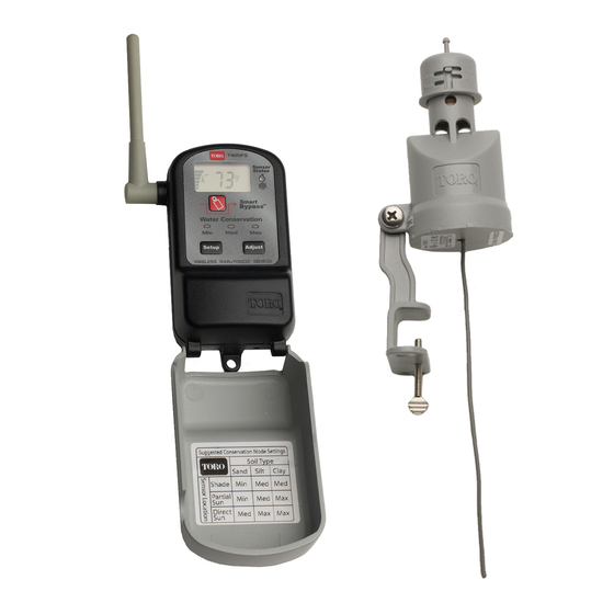
Smart Bypass Feature ..... . . 16 Introduction The Toro wireless rain sensor system, model TWRS-I for rain sensing and TWRFS-I for rain and freeze sensing, is a powerful, water conservation and management tool that connects your automatic irrigation system to actual environmental factors vital to the health and maintenance of your landscape. - Page 3 The wireless sensor system is comprised of a programmable, weather-resistant receiver module and a sensor module with built-in transmitter. The receiver installs next to the irrigation controller and connects to the controller’s 24 Vac power source and sensor input terminals (if equipped) or splices directly into the irrigation valve common wire.
-
Page 4: Getting Started
Getting Started The wireless rain sensor system is designed for easy installation, setup and years of trouble-free operation. In most cases, the system components can be installed and fully operational within minutes. All you will need is a Phillips screwdriver and basic do-it-yourself skills. If you have problems with any portion of the installation, or the product does not seem to function properly, refer to the Troubleshooting section on page 22 first. - Page 5 Step 3 A sensor installation site is chosen and the system is tested again to verify operation. See page 10. Step 5 The sensor module is installed. See page 11. Step 4 The sensor is adjusted to the preferred rainfall activation level. See page 11. Step 6 The operating features are set to your preferences.
-
Page 6: Receiver Module Features
Receiver Module Features 1– Setup Button–Accesses the receiver setup and operating features. 2– Adjust Button–Selects settings within the receiver setup and operating features. 3– Mast Antenna–Adjusts easily for best signal reception. 4– Digital Display–High-resolution LCD screen provides visual reference for sensor system operating features. 5–... -
Page 7: Installing The Receiver Module
Installing the Receiver Module Important: Installation of this product must comply with national and local building and electrical codes. For assistance, contact a professional irrigation system contractor in your area. The receiver module is suitable for either indoor or outdoor installation. Select a location next to the controller that provides the following conditions: •... - Page 8 Connecting the Receiver Wires CAUTION: The receiver requires continuous 24 Vac power for operation. Connecting to higher power will result in irreparable damage. Ensure that power to the controller has been removed prior to connecting the receiver wires. The sensor system is designed to work with most makes and models of irrigation controllers. •...
- Page 9 For a Normally-Open sensor type, attach the Yellow wire to the remaining Sensor terminal. Tape back the Brown wire. See Figure 3. 4. Attach the two Red wires to the 24 Vac terminals in either order. Important: Most controllers equipped for sensor connection provide a switch to control the sensor circuit.
-
Page 10: Initial Sensor System Test
2. When power is applied to the receiver, the “Min” Water Conservation indicator will illuminate. The TWRS-I receiver will display alternating boxes and the TWRFS-I receiver will display two flashing bars as shown in Figures 5 and 6. 3. Holding the sensor module next to the receiver, press and hold the sensor test spindle down for at least 15 seconds to establish communication. -
Page 11: Sensor Module Features
Sensor Module Features 1– Rain Threshold Adjustment–Adjusts the rain sensor to accumulate 3mm, 6mm,12mm or 19mm of rainfall before signaling the receiver to hold watering. The factory default setting 6mm. 2– Sensor Test Spindle–Pressed to manually activate the sensor for setup and test procedures. 3–... -
Page 12: Rain Sensor Site Selection
Rain Sensor Site Selection Choosing the right installation site for the sensor module is key to obtaining the maximum benefit from your sensor system. For best results, choose a sensor installation site that provides: • Unobstructed exposure to rainfall–away from overhangs, tree branches, etc. •... -
Page 13: Installing The Sensor Module
Installing the Sensor Module 1. Adjust the sensor module to the preferred rainfall threshold activation point. The settings, provided in metric on one side of the cap and U.S. standard on the other, include 3mm, 6mm, 12mm and 19mm. The factory setting is 6mm and is generally a good starting point. - Page 14 3. To install the sensor on a length of thick-walled PVC pipe, remove and replace the Quick Clip bracket with the pipe-mount adapter. To provide friction between the components, ensure the star washer is installed between the adapter and housing tab as shown in Figure 14. 4.
-
Page 15: Freeze Sensor Site Selection
Freeze Sensor (model TWRFS-I) Site Selection To ensure optimum freeze sensor operation, the sensor module installation site should meet the site criteria of the rain sensor in addition to the following conditions: • Located in the coldest portion of the landscape. •... -
Page 16: Set Centigrade Or Fahrenheit Scale
Set Temperature Activation Threshold (TWRFS-I models only) The freeze sensor temperature activation threshold is adjustable from 2°C to 7°C ( 35°F to 45°F). When the air temperature reaches the threshold setting, the freeze sensor activates the receiver, and the Freeze Status indicator will turn on. The sensor system will return to the Monitor mode when the outside air temperature rises above the sensor threshold temperature. -
Page 17: Water Conservation Feature
Water Conservation Feature – By simply choosing the Minimum (Min), Medium (Med) or Maximum (Max) conservation level that corresponds to your landscape’s soil type and the sensor location, a dry-out period, adjusted for actual rainfall duration, is inserted after the sensor system resets to delay the resumption of automatic watering. -
Page 18: Smart Bypass Feature
Smart Bypass Feature Once the rain sensor becomes active, it can be easily bypassed by pressing Smart Bypass button. When the rain sensor is bypassed, the Sensor Status indicator and flashing. See Figure 20. The controller will resume automatic watering operations as scheduled. The rain sensor will stay in the Bypass mode until it automatically resets to the Monitor mode, or is returned to the active mode by pressing the Water Delay Feature... -
Page 19: Battery Strength Display Feature
Signal Strength Display This feature displays sensor signal strength on a digital scale ranging from 0.0 to 10.2. 1. Press the Setup button as needed to display the antenna icon and the digital readout. The display will indicate the strength of the last received signal. -
Page 20: Dry Out Feature
Dry Out Feature The Dry Out feature is provided to override the Water Conservation baseline level, allowing the dry-out delay period to be set with more accuracy from 0.5 to 4.0 days in 0.5-day increments. Note: Before using the Dry Out feature, allow the sensor system to normalize by cycling through rain and/or freeze activation several times. - Page 21 Loss of Communication If the sensor and receiver do not communicate within a 24-hour period, the Figure 25 sensor system will remain in its current state (Active or Monitor). To alert you to this condition, the Warning icon will be displayed. The Antenna icon and current air temperature (TWRFS-I only) will be flashing and the signal bar indicator will be cleared.
-
Page 22: Turn Receiver Module Off And On
Turn the Receiver Module Off and On 1. To turn the receiver module Off, press and hold the displayed (approximately 5 seconds), then release. 2. To turn the receiver On, press the normal display mode within approximately 10 seconds. Set or Restore the Sensor Address Code The receiver and sensor modules are factory-matched to communicate using a specific address code. -
Page 23: Sensor Module Battery Replacement
Sensor Module Battery Replacement 1. Unscrew and remove the bottom cap from the sensor housing. 2. Grasping the edges of the circuit board assembly, carefully slide the circuit board assembly out of the housing. 3. Remove the battery cover and batteries. 4. -
Page 24: Troubleshooting
Troubleshooting If you encounter problems at any point in the installation process, or the components do not function properly, try the Troubleshooting procedures first. If the problem is not listed or the remedy does not resolve the problem, contact your local Toro irrigation distributor for assistance. K Signal strength is weak or inconsistent. - Page 25 K The receiver display is blank. • Check the 24 Vac power connections. The red power wires from the receiver must be connected to the controller’s 24 Vac power source. Make sure the power wires are not connected to the station or pump/master valve terminals. These terminals only provide 24 Vac power when the controller is operating the sprinkler zones.
-
Page 26: Specifications
Relay Contacts Output: Normally Open (NO) and Normally Closed (NC) 3A at 24 Vac Note: The Toro Wireless Rain and Rain/Freeze Sensor series, models TWRS, TWRS-I, TWRFS and TWRFS-I, are patented with the following U.S. patents pending: 6,452,499, 5,101,083 and... -
Page 27: Warranty Information
The Toro Promise – Five-year Limited Warranty The Toro Company and its affiliate, Toro Warranty Company, pursuant to an agreement between them, jointly warrants, to the owner, each new piece of equipment (featured in the current catalog at date of installation) against defects in material and workmanship for for a period described below, provided they are used for irrigation purposes under manufacturer's recommended specifications. - Page 28 Electromagnetic Compatibility The TWRS-I and TWRFS-I wireless rain sensor series is CISPR 22 class B compliant. FCC ID: OF7TWRS IC: 3575A-TWRS Important: Changes or modifications to this unit, not expressly approved by the party responsible for compliance, could void the authority to operate the equipment.