Trane Z WAVE TZEMT400AB32MAA User Manual
Thermostat for heating and cooling hvac system control z-wave rf communications enabled
Hide thumbs
Also See for Z WAVE TZEMT400AB32MAA:
- User manual (28 pages) ,
- Installation instructions (1 page) ,
- Installation instructions manual (32 pages)
Table of Contents
Advertisement
Contents
Product Specifications ............................................2
Overview ...................................................................3
Z-Wave™ Thermostat ................................................ 3
Display operation ........................................................ 3
Z-Wave™ Operation and Programming .................4
Inclusion ...................................................................... 4
Exclusion ..................................................................... 4
Inclusion and Exclusion .............................................. 4
Operation ..................................................................5
Thermostat Control Buttons ........................................ 5
LEDs ........................................................................... 5
Thermostat Screens .................................................... 5
Thermostat Control Screen ......................................... 5
Minimized Thermostat Screen ................................... 5
Menu Selection Screen ............................................... 5
Schedules Screen ...................................................... 5
User Settings Screen .................................................. 6
Usage Graph ............................................................... 6
ESM Setpoints ............................................................ 6
ZWave Install ............................................................... 6
Thermostat Info Screen .............................................. 6
Thermostat Control Screen ....................................7
Temperature Display ................................................... 7
Setpoint Display .......................................................... 7
Clock Display .............................................................. 7
Thermostat Control Screen Buttons ........................... 8
MENU Button ............................................................. 9
MODE Button ............................................................ 10
FAN Button ................................................................ 11
RUN/HOLD/ESM Button ........................................... 11
LED Displays ............................................................. 12
Thermostat
Model TZEMT400AB32MAA
User Guide
Main Menu ..............................................................13
Schedules ................................................................. 14
Heat and Cool Schedules ......................................... 15
Copy Schedule .......................................................... 16
User Settings ............................................................ 17
Set Clock ................................................................... 18
Filter Service ............................................................. 19
Maint Service ............................................................ 20
Sensor Calibration..................................................... 21
Backlite/Display ......................................................... 22
Thermostat Info ........................................................ 23
Installer Settings Menu (Hidden Screen) ................ 24
Installer Settings Summary ....................................... 26
HVAC System Connection ....................................28
HVAC System Compatibility ...................................... 28
Remote Communications .......................................... 28
Standard Gas/Electric HVAC System Wiring ............ 29
Heat Pump HVAC System Wiring ............................. 30
HVAC System Operation and Setup .....................31
General Heating and Cooling Operation ................... 31
Standard HVAC System Types ................................ 31
Setup ......................................................................... 31
Heat Pump HVAC System Types ............................. 31
Setup ......................................................................... 32
Installation ..............................................................33
Power ........................................................................ 33
Warranty .................................................................34
Advertisement
Table of Contents

Related Manuals for Trane Z WAVE TZEMT400AB32MAA


Summary of Contents for Trane Z WAVE TZEMT400AB32MAA
-
Page 1: Table Of Contents
Thermostat Model TZEMT400AB32MAA User Guide Contents Product Specifications ...2 Overview ...3 Z-Wave™ Thermostat ... 3 Display operation ... 3 Z-Wave™ Operation and Programming ...4 Inclusion ... 4 Exclusion ... 4 Inclusion and Exclusion ... 4 Operation ...5 Thermostat Control Buttons ... 5 LEDs ... -
Page 2: Product Specifications
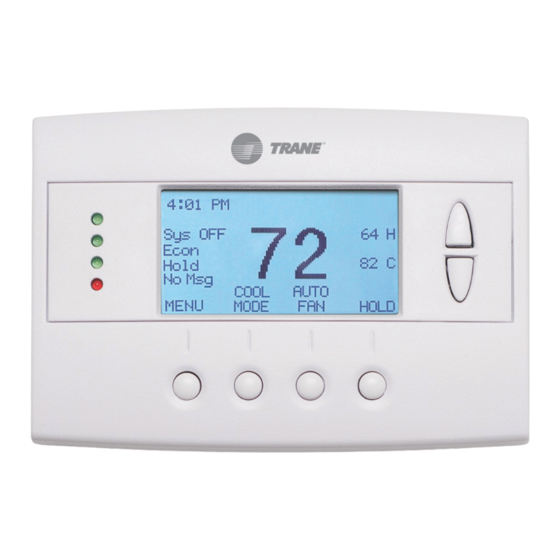
Product Specifications Product Model: TZEMT400AB32MAA Product: Thermostat for Heating and Cooling HVAC System control. Thermostat Size: 5.7” wide x 4.0” height x 1.2” depth Display: Graphical LCD, 2.75” x 1.5”, 64x128-pixel Backlight: Yes, Blue/white, Controllable, on, off, timeout Contrast: Adjustable on screen Buttons: 6 LEDs: 4 (3 green, 1 red) Power: 24VAC from HVAC System... -
Page 3: Overview
Overview Z-Wave™ Thermostat The Z-Wave™ thermostat provides for typical thermostat control of a central heating and cooling HVAC system plus has the added feature of Z-Wave™ communications for remote control. The thermostat has a large, backlit graphical display, control buttons, status LEDs and a temperature sensor. The thermostat can display multiple screens for different functions of the thermostat. -
Page 4: Z-Wave™ Operation And Programming
Z-Wave™ Operation and Programming Z-Wave™ controllers from various manufacturers may support the Z-Wave™ Thermostat General V2 Device class used by the Trane Z-Wave™ Thermostat. The following procedure will allow the thermostat to be added to a Z-Wave™ network. If you are using a controller that is not a Schlage bridge, consult the instructions that came with the controller to find out how to enroll a new device. -
Page 5: Operation
Operation Thermostat Control Buttons The Thermostats buttons are “Soft Keys” meaning that they change functions when you change screens. The function of the button is defined by “on-screen labels” that are dynamic and change when you change screens. LEDs The Thermostat has four LED’s that displays status information. The LEDs have dynamic “on-screen” labels that can change with the screen being displayed. -
Page 6: User Settings Screen
Thermostat User Guide User Settings Screen This screen is a submenu of user settings for the initial setup of the thermostat. You can set the clock, minimized screen timeout, Fahrenheit or Centigrade selection, sensor calibration and display settings. Usage Graph Shows daily heating and cooling runtime hours for a week. -
Page 7: Thermostat Control Screen
Thermostat Control Screen The main Thermostat Control Screen is the default display screen and is the screen that is normally displayed on the Thermostat. Temperature Display The Thermostat will display the current temperature from the internal temperature sensor. Setpoint Display The heating and cooling setpoints are displayed next to the Setpoint Up/Down buttons. -
Page 8: Thermostat Control Screen Buttons
Thermostat User Guide Thermostat Control Screen Buttons Setpoint Up and Down Buttons Pressing the Up or Down button in the main Thermostat Control Screen will take you to the Heating Setpoint or Cooling Setpoint screen, as shown below. Heating HEATING SETPOINT Cooling Setpoint Down... -
Page 9: Menu Button
MENU Button The Menu button changes the screen display to the MAIN MENU screen which show what other functions are available on the Thermostat. These are dynamic and can change with the version of the thermostat you have, but the standard ones include: Main Thermostat Screen Menu Button... -
Page 10: Mode Button
Thermostat User Guide MODE Button The MODE button controls the HVAC system mode. The current mode selected is displayed above the button. Pressing the MODE button will take you to the System Mode screen. Pressing the Up or Down buttons will scroll through the mode options. Pressing done or waiting for the screen to timeout will select the new mode. -
Page 11: Fan Button
FAN Button The FAN button controls the HVAC system’s MANUAL fan. The current manual fan mode is displayed above the button. Pressing the FAN button will take you to the FAN MODE screen shown below. Fan Mode Screen Done Normally the FAN mode is in the Auto mode (the system fan is automatically controlled by HVAC system). If you want the FAN on manually, select the ON mode. -
Page 12: Led Displays
Thermostat User Guide LED Displays The Thermostat Control Screen has the following LED and on-screen labels numbered from top to bottom. • LED 1 Green: System Operation display • Sys Off displayed = HVAC system is OFF; LED Off. • WAIT displayed = Minimum Off Time (MOT)delay is active;... -
Page 13: Main Menu
Main Menu The Thermostat has a menu tree that can be accessed by pressing the “Menu” button on the Main Thermostat screen. Various configurations of the Thermostat can have different screen contents. The first screen that will come up is the Menu Selection screen. -
Page 14: Schedules
Thermostat User Guide Schedules Schedules is an optional menu item. It will only show up in the menu list if “Schedules” is enabled in the Installer settings for the thermostat (See page 23). Provides for local schedule control. The Schedules Screen allows you to review and set the setback schedule for the thermostat. -
Page 15: Heat And Cool Schedules
Heat and Cool Schedules When you select the Heat and Cool Schedule menu item, the “day” Schedule programming screen opens and the schedule for current day will be displayed. Use the scroll buttons to highlight the data to be modified. Once the data has been highlighted, use the +/- buttons to change the value of the data. -
Page 16: Copy Schedule
Thermostat User Guide Copy Schedule The Copy Schedule screen is a sub screen of the Schedule screen. The Copy Schedule screen allows you to copy a day’s schedule to another day or group of days. First select the day to be copied in the Schedule screen. Scroll to the “c” at the bottom of the Schedule screen to highlight it. -
Page 17: User Settings
User Settings The User Settings screen allows you to set or change various user options of the thermostat such as the Clock, Minimized Screen timeout, Fahrenheit/Celsius mode, Sensor Calibrations, and Display settings. Menu options: • Set Clock: Select this menu item to go to the Clock setting screen. •... -
Page 18: Set Clock
Thermostat User Guide Set Clock The Set Clock screen allows you to set the Thermostat’s internal clock. To set the Time and Date, move the cursor with the navigation arrows until the data you want to change is highlighted. Using the + and – buttons to increment or decrement the data to the desired setting. When finished, press the SET button to return to the Main Menu screen or wait for screen to timeout. -
Page 19: Filter Service
Filter Service The Filter Service screen will show the accumulated Filter Runtime hours as well as the Service Interval that will be used to trigger a Filter Message. Any type of HVAC operation that causes the HVAC system fan to run will cause the Filter Runtime value to increase. -
Page 20: Maint Service
Thermostat User Guide Maint Service The Maintenance Service screen will show the accumulated Heat and Cool Runtime hours as well as the Service Interval that will be used to trigger a Maintenance Message. Any HEAT or COOL type of HVAC operation will cause the respective Runtime values to increase. -
Page 21: Sensor Calibration
Sensor Calibration The Sensor Calibration screen allows you to change the temperature calibration of the internal temperature sensor. You can change the temperature calibration by +/- 7 degrees. When the Sensor Calibration screen is selected it will show the current temperature calibration (The (75) in the example screen below) and the current number of degrees of offset being applied (1 deg in the example). -
Page 22: Backlite/Display
Thermostat User Guide Backlite/Display The Backlite/Display screen allows you to set the Backlite timeout and contrast. Backlite Timeout: Sets the time from last button press that the backlite will timeout and turn off. The timeout value is adjustable from 0 or 20 to 120 seconds. If set to “0”, the Backlite will always be ON. If set in the range of 20 to 120 seconds, the Backlite will turn OFF after the selected time expires. -
Page 23: Thermostat Info
Thermostat Info The Thermostat Info screen displays the current configuration of the Z-WAVE Thermostat. This information is useful for quick check of firmware versions and HVAC system setup. It also shows the Zwave network setting. Thermostat information displayed is: • Thermostat - Model and firmware version number. -
Page 24: Installer Settings Menu (Hidden Screen)
Thermostat User Guide Installer Settings Menu (Hidden Screen) The Installer Settings screen is a hidden screen designed for installer use only. Do not change any settings in this screen unless you are a qualified service technician. Changing these settings will affect the operation of the heating/cooling system. - Page 25 Heating Delta Stage 2 ON Sets the delta from setpoint that stage 2 heating starts. Heating Delta Stage 2 OFF Sets the delta from setpoint that stage 2 heating stops. Stage 2 turns off at setpoint + Delta Stage 2. Heating Delta Stage 3 ON Sets the delta from setpoint that stage 3 heating starts.
-
Page 26: Installer Settings Summary
Thermostat User Guide Installer Settings Summary Setting Range Display Lock Y or N F/C Mode C or F Screen Timeout 0-240 Schedule Enable Y or N Max heat setpoint 55F-90F (12C-32C) Min cool setpoint 60F-99F(15C-37C) Min Run Time (MRT) 1 – 9 Min Off Time (MOT) 5 –... - Page 27 Installer Settings Screen Screen navigation buttons: Done Return to Main Menu screen Increase by 1 or change from N to Y Decrease by 1 or change from Y to N Selec Select menu item to go to a submenu Installer Settings Display Lock System Settings Max Heat SP...
-
Page 28: Hvac System Connection
HVAC System Connection The thermostat connects to the HVAC system’s thermostat connections just like a traditional thermostat does. HVAC System Compatibility The thermostat is compatible with most heating and cooling systems. There are two types of HVAC systems: Standard (gas/electric) and Heat Pump systems. The system type is selectable from the Installer Screen – System Settings – Mechanical Settings submenu. -
Page 29: Standard Gas/Electric Hvac System Wiring
Standard Gas/Electric HVAC System Wiring Z-WAVE Thermostat 24COM 24RC 24RH W1 HEAT W2/O G FAN Y1 COMP Y2 COMP JP1: internal RC/RH Jumper See notes Installation Notes Standard HVAC System Setup System Type: Set the system type to Gas/Elect in the Mechanical Settings menu of the Installer Setup. This is the default setting. -
Page 30: Heat Pump Hvac System Wiring
Thermostat User Guide Heat Pump HVAC System Wiring Z-WAVE Thermostat 24COM 24RC 24RH W1 HEAT W2/O G FAN Y1 COMP Y2 COMP JP1: internal RC/RH Jumper Do not cut for HP systems Installation Notes Heat Pump HVAC System Setup System Type: Set the mechanical system type to Heat Pump in the Installer Settings Menu Single Stage Compressor Systems use Y1 for stage 1 heating/cooling, and W1 for stage 2 Aux Heating. -
Page 31: Hvac System Operation And Setup
HVAC System Operation and Setup General Heating and Cooling Operation In the HEATING mode, the heating system will be turned on at one degree below the setpoint and will turn off at the setpoint. This turn on and turn off offset is referred to as the heating setpoint “delta T” and is adjustable in the Installer Settings menu of the THERMOSTAT. -
Page 32: Setup
Thermostat User Guide The third stage of heating will be turned on when the current temperature falls 3 deg below the current setpoint and will turn off at the setpoint. Setup Heat Pump System Type Selection To set the Thermostat for Heat Pump HVAC operation, change the Type in the Installer Settings – System Settings – Mechanical Settings menu option to Heatpump. -
Page 33: Installation
Installation Power The thermostat requires 24VAC power from the HVAC system it is controlling. Connect the 24VAC Common (typically the Blue wire/terminal) and 24VAC R (typically the Red wire/terminal) from the HVAC system to the thermostats HVAC System terminal block 24VCom and 24V RH or 24V RC terminals (the RH and RC terminals are default tied together) Common or Split Transformer Systems Most HVAC systems have a common heating and cooling transformer. -
Page 34: Warranty
Warranty Trane Remote Energy Management Thermostat Limited One (1)-Year Electronics and Mechanical Warranty Subject to the terms and conditions of this Limited One (1)-Year Electronics and Mechanical Warranty, Trane warrants that, if within one (1) year from Original Date of Purchase, the Purchased Product fails due to defect in manufacture, material or workmanship, Trane will provide a replacement for the Purchased Product or refund the Original Purchase Price, at its sole option, to the Original Purchaser occupying the premises in which the Purchased Product was originally installed.
Need help?
Do you have a question about the Z WAVE TZEMT400AB32MAA and is the answer not in the manual?
Questions and answers