Bogen TPU250 Installation And Use Manual
Bogen communications installation and use manual telephone paging amplifier tpu250
Hide thumbs
Also See for TPU250:
- Information (13 pages) ,
- Installation and use manual (12 pages) ,
- Specifications (2 pages)

Related Manuals for Bogen TPU250


Summary of Contents for Bogen TPU250
- Page 1 TPU250 Telephone Paging Amplifier Installation and Use Manual © 2000 Bogen Communications, Inc. All rights reserved. 54-5900-01r1 0001...
-
Page 2: Important Safety Information
© 2000 Bogen Communications, Inc. All Rights Reserved. Printed in Korea. Notice Every effort was made to ensure that the information in this guide was complete and accurate at the time of printing. However, information is subject to change. Important Safety Information... -
Page 3: Table Of Contents
Contents INTRODUCTION ...4 PACKAGE CONTENTS...4 INSTALLATION...5 Mounting ...5 Wall Mounting...5 Rack Mounting ...5 WIRING CONNECTIONS ...6 Input Wiring...6 Tel Input...6 Music Input ...7 Microphone Input ...7 Night Ringer Connections ...8 Bridging Inputs ...8 Input Cover Replacement ...8 ‘ Output Wiring ...9 Speaker Connection ...9 Additional Power Amplifier ...10 Line-Matching Transformer WMT 1 A Connector ...10... -
Page 4: Introduction
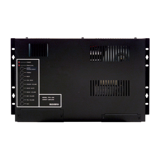
CONTACT MUTE Figure 1: Telephone Paging Amplifier This document describes the Bogen TPU250 250-watt Telephone Paging Amplifier (see Figure1). This is a full-featured, wall-mounted amplifier that provides inputs for dry loop 600-ohm telephone page signal, background music source, and low impedance microphone.Automatic music mute is provided when making a telephone... -
Page 5: Installation
Rack Mounting The amplifier is designed for wall mount applications but can also be mounted in a standard 19" rack. The TPU250 amplifier weighs 31 lbs. NOTE: The amplifier will produce heat during operation which will rise and may cause problems for temperature-sensitive equipment mounted above it. Mount the amplifier near the top of the backboard (for wall mounting) or rack (for rack mounting) so that no other equipment will be above it. -
Page 6: Wiring Connections
CONTACT CLOSURE A +24/48 POWER SUPPLY (TRUNK ACCESS ONLY) -24/48 (0.1A) MODE SWITCHES Page 6 of 12 Telephone Paging Amplifier MIC VOLUME MODEL TPU250 TEL VOLUME 250 WATT AMPLIFIER BOGEN COMMUNICATIONS APHEX MUSIC IN BRIDGING MUSIC MUSIC CONTACT MUTE RING... -
Page 7: Music Input
If a balanced input is needed, use a Bogen Line-Matching Transformer WMT1A (sold separately) to balance the music input.The WMT1A is also effective in breaking ground loops that cause hum. -
Page 8: Night Ringer Connections
500 watts. However, bridging does not increase the size of the load a TPU250 can individually handle. Once bridged, each amplifier will amplify the inputs present on both amplifiers. The level control of a particular input on an amplifier will control the volume of this signal on both amplifiers. -
Page 9: Output Wiring
GND terminal. NOTE: The amplifier output terminal strip includes a terminal for 25V speaker connections. This is provided for special applications and is generally not used. Output Terminal Strip MIC VOLUME MODEL TPU250 TEL VOLUME 250 WATT AMPLIFIER BOGEN COMMUNICATIONS APHEX... -
Page 10: Additional Power Amplifier
Additional Power Amplifier An external power amplifier can be used with the TPU250 amplifier. You must first add a resistor voltage divider to the telephone amplifier, as illustrated in Figure 8. Connect a patch cord to the high-level/high-impedance input of the booster amplifier. -
Page 11: Operation
Operation IMPORTANT: Before plugging the amplifier into an AC outlet, turn all volume controls to their full counterclockwise positions. Indicators POWER IND The POWER IND LED illuminates whenever AC power is applied to the amplifier (there is no power switch on the amplifier). PEAK LEVEL The PEAK LEVEL LED illuminates whenever the speaker output signal level approaches its maximum level. - Page 12 BASS and TREBLE Bass and treble controls are provided to adjust the high frequency and low frequency response of the paging system. Reference positions are provided for these controls. When set to these positions, the frequency response of the system will be flat. Set the controls to the customer’s satisfaction.
Need help?
Do you have a question about the TPU250 and is the answer not in the manual?
Questions and answers