
Related Manuals for Duplo DSC-10/20


Summary of Contents for Duplo DSC-10/20
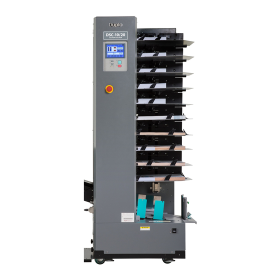
- Page 1 INSTRUCTION MANUAL COLLATOR SUCTION COLLATOR DSC-10/20 Be sure to read this manual prior to use. Please leave this manual at the site of use for easy reference.
- Page 2 Introduction Thank you for purchasing a Duplo product. Be sure to read this manual prior to using the product. After reading, leave the manual at the site of use for easy reference whenever questions related to the product arise in the future.
- Page 3 Duplo International Ltd, Automated Precision House, Hamm Moor Lane, Addlestone, Surrey, KT15 2SD, United Kingdom KONFORMITÄTSERKLÄRUNG Die Duplo Corporation mit Sitz in 1-6, Oyama 4 chome, Chuo-ku, Sagamihara, Kanagawa 252-5280 Japan, erklärt hiermit, dass das Produkt (oder die Produkte) die in den Vorschriften definierten Bestimmungen erfüllt. Die Bezugstabelle ist unten aufgeführt.
- Page 4 Duplo International Ltd, Automated Precision House, Hamm Moor Lane, Addlestone, Surrey, KT15 2SD, United Kingdom DECLARATION D’INTEGRATION Duplo Corporation, dont le siège social est situé au 1-6, Oyama 4-chome, Chuo-ku, Sagamihara, Kanagawa 252-5280, Japon, déclare : • que les exigences essentielles de la Directive Machines sont appliquées au(x) produit(s) mentionné(s) dans le tableau ci-après, •...
- Page 5 EN61000-6-4: 2007 Responsabile della documentazione tecnica all’interno della Comunità Europea: Duplo International Ltd, Automated Precision House, Hamm Moor Lane, Addlestone, Surrey, KT15 2SD, United Kingdom DECLARACIÓN DE INCORPORACIÓN DEL PRODUCTO (O LOS PRODUCTOS) Duplo Corporation, con domicilio en 1-6, Oyama 4-chome, Chuo-ku, Sagamihara, Kanagawa 252-5280, Japón, declara que: •...
- Page 6 For EU Disposal of Old Electrical & Electronic Equipment Eliminación de residuos de aparatos eléctricos y electrónicos This symbol (the symbol of the crossed out wheeled bin) indicates that in European countries this product Este símbolo (un cubo de basura tachado) indica should not be disposed of as household waste.
-
Page 7: Safety Precautions
Safety Precautions Safety Precautions In this manual, operations and handling of the unit which are hazardous are described using the following marks to prevent personal injury or property damage to the user and others. Ignoring this mark could result in the possibility of serious injury or even death. -
Page 8: Operating Environment
Safety Precautions Operating Environment Operate this unit in the following environment. • where the temperature range is between 5 and 35°C/41 and 95°F (-10 to +50°C/14 to 122°F in storage) • where the humidity range is between 20 and 85% RH (10 to 90% RH in storage, however no condensation) •... -
Page 9: Maintenance / Other
Safety Precautions Maintenance / Other Do not damage the power cord or power plug. Do not scratch, alter, bend, twist, pull or place heavy objects on the power cord or power plug. This could result in damage, a fire or an electrical shock. Do not touch the power switch with wet hands. -
Page 10: Warning / Caution Labels
Safety Precautions WARNING / CAUTION Labels (For North America,EU) (For North America,EU) (For North America) (For North America) "WARNING" and "CAUTION" labels are pasted on the machine to ensure user safety. Do not remove or change them. When the labels become dirty or are lost, be sure to contact your dealer for a new one. -
Page 11: Safety Function And Driving Section
Safety Precautions Safety Function and Driving Section • SAFETY FUNCTION Use the emergency stop switch only when you need to stop the machine urgently. In normal use, press the stop key on the control panel. To stop the machine without using the stop key or emergency stop switch •... -
Page 12: Table Of Contents
Contents Contents Setting ................2-36 Safety Precautions ..........i 5-4. Panel Brightness Setting........2-37 Power Supply .................i 5-5. Auto Backlight Off Setting .........2-38 Operating Environment ............ii 5-6. Buzzer Setting ............2-39 Maintenance / Other ............... iii 5-7. Count Display Setting ..........2-39 WARNING / CAUTION Labels ..........iv Safety Function and Driving Section ......... -
Page 13: Chapter 1 Prior To Use
Chapter 1 Prior to Use Chapter 1 Prior to Use Features of This Machine Two DSC-10/20s can be used together. When using two DSC-10/20s, the one on the left side as seen from the control panel is called Tower A and the one on the right side is called Tower B. -
Page 14: Names And Functions Of Parts
Names and Functions of Parts Chapter 1 Prior to Use [10] [11] Name Function Control Panel Consists of the touch panel, keys and lamps. Used for operating or setting the machine. Emergency Stop Switch Press this switch to stop operations in emergency. Paper Feed Bin Base Supports the paper feed table Connecting Plate... - Page 15 Chapter 1 Prior to Use [11] [10] Name Function Separating Air Adjustment Adjusts the separating air by changing the position of the shutter. Paper Guide Presses the edge of the paper to hold the paper in place. Paper Feed Table Used for loading paper to be collated.
- Page 16 Chapter 1 Prior to Use [10] [10] [10] [10] Name Function Paper Receiving Stopper3 Prevents collated paper from falling apart during the sorting process. Paper Receiving Stopper2 Receives the leading edge of ejected collated paper. Paper Receiving Stopper1 Holds paper receiving stoppers 2 and 3. Auxiliary Stopper Depending on the paper size used, attach one of these to paper receiving stopper 1 or side guide F to help align paper.
-
Page 17: Accessories
Accessories Chapter 1 Prior to Use Name Paper Guide Movable Paper Guide Optional Parts Name Paper Receiving Stopper3 Paper Receiving Stopper1 Back Jogger Auxiliary Stopper Paper Receiving Stopper2... -
Page 18: Names And Functions Of Control Panel
Names and Functions of Control Panel Chapter 1 Prior to Use 5-1. Control Panel Name Function Touch Panel Displays information on the machine's state or setting. Touching the panel changes the displayed information. Start Key Touching this key for about one second in the stop state starts operations. When pressed during processing, the machine enters the waiting mode (*). -
Page 19: Touch Panel
Chapter 1 Prior to Use 5-2. Touch Panel MAIN Menu <No. of rejects display area> [10] [11] [19] <Total no. of sets display area> [12] [13] [19] [14] [18] [17] [16] [15] Name Function Main Tab Displays the main menu. MODE Tab Displays the mode screen. - Page 20 Chapter 1 Prior to Use [15] No. of Sets Display Switching Touching this key switches the display between the number of sets, number of rejects, and total count. When two DSC-10/20s are connected (one will be called tower A and the other tower B in this manual), this mode screen will only be displayed on tower A.
- Page 21 Chapter 1 Prior to Use MODE Screen <MODE 1> This screen is not displayed on tower B when connected. Name Function Paper Ejection Direction Key Switches the paper ejection direction to the right or left. Block Key Used for selecting the block switching method when the block colla- tion mode is selected.
- Page 22 Chapter 1 Prior to Use SETTINGS Screen <SETTINGS 1> Name Function Double-Feed Detection Key Used for setting double-feed detection (thin paper, thick paper, OFF, and manual). Paper Feed Error Detection Key Used for setting paper feed error detection (ON, OFF, manual). Number of Sets Display Method Key Used for switching the number of processed sets display method to count up or count down.
- Page 23 Chapter 1 Prior to Use OPTIONS Screen <LUL-HM> This is not displayed when LUL-HM is not connected. Name Function Downstream Unit Handfeed Key Switches to the downstream unit to the manual feed standby state. Merge Collation Key Switches to the collation setting which starts paper feed from the tower and merges the paper when manual feed sets are inserted in the hand marry.
- Page 24 Chapter 1 Prior to Use Air Adjustment Screen [10] [11] Name Function Separating Air Manual Key Used for switching to the separating air setup screen. Separating Air Down Key Used for decreasing the strength of the separating air of all bins. Separating Air Up Key Increases the strength of the separating air of all bins.
-
Page 25: Chapter 2 Basic Operation
Chapter 2 Basic Operation Chapter 2 Basic Operation Flowchart of Operations P.2-2) Turn on the power. P.2-2) Set the paper eject direction. P.2-3) Set the block mode. All Bins Mode P.2-4) Insert interleaf? P.2-5) Set the program mode. Set the interleaf insert mode. Alternate Mode P.2-6) Set the stacker. -
Page 26: Operation Procedures
Operation Procedures Chapter 2 Basic Operation 2-1. Power On <When Connected> Set the main power switches of both collators to the "I" side. Set the power switch of tower A to the "I" side. • Both collators can be turned ON/OFF us- ing only the power switch of tower A if the Main power switch power switch of tower B is set to "... -
Page 27: Setting The Block Mode
Chapter 2 Basic Operation Select the MODE menu. Set the Paper Eject Direction to right side ( ) or left side ( ). Select right side ejection when ejecting pa- per to the stacker and left side ejection when ejecting paper to the downstream unit. 2-3. -
Page 28: Setting The Program Mode
Chapter 2 Basic Operation Setting Method Select the MODE menu. Set the Block Mode as follows: • ALL Paper feed bins are not divided into blocks. • 1/2 Paper feed bins are divided into two blocks. • 1/4 Paper feed bins are divided into four blocks. 1/4 can be selected only when two collators are used. - Page 29 In the figure, the all bin mode is selected for operations using the DSC-10/20 only with the paper load- ing method set to left side ejection. As the paper loading method will differ according to the number of towers connected, and the paper ejection direction, refer to “2-6.
-
Page 30: Setting The Stacker
Chapter 2 Basic Operation Touch Perform Step 3 when interleaf mode 1 or 2 is selected. Skip it when the all bins mode or alternate mode is selected. Enter after how many sets to insert the interleaf on the numerical keypad. Touch to return to the MODE menu screen. - Page 31 Chapter 2 Basic Operation Set the Stack Method. • Offset Stacking Mode( Shift the paper to the left and right for each set. This mode is appropriate for dividing sheets into subsets. • Straight Stacking Mode ( All sheets are stacked normally. A.
- Page 32 Chapter 2 Basic Operation 7) Set the auxiliary stopper to paper receiving stopper 1. The auxiliary stopper is used for preventing shifting of paper above A4 size. It can be removed when using paper below A4 size. 8) Adjust the side guide F to the paper size. When using A5 paper, adjust paper receiving stopper 1 and side guide F to the positions shown in the following figure.
- Page 33 Chapter 2 Basic Operation B. Stacking Mode The following describes sorting operations using A4 paper as an example. 1) Set the paper receiving method to “Stack- ing”. 2) Set the conveyance speed to 1. • Normally set to “1”. Paper may bend when using only a few sheets of thin paper.
-
Page 34: Loading The Paper
Chapter 2 Basic Operation 7) Remove the paper receiving stopper 2. It need not be removed in operations, but removal is recommended. 8) Press the key or load the paper on the ejection stacker. When performing preset, load paper on the paper feed bin. - Page 35 Chapter 2 Basic Operation 2-6-2. Paper Direction • Left side ejection After collating, the top side of the topmost sheet faces up. P.10 P.10 • Right side ejection After collating, the bottom side of the bottom- most sheet faces up. P.10 P.10 2-6-3.
- Page 36 Chapter 2 Basic Operation When using the block mode, load the first page on the topmost bin of each block. Block Mode 1/2 Block Mode 1/4 No.1 No.3 No.1 No.2 No.2 No.4 P.10 P.10 • Right side ejection Load the first page on the undermost bin. When using two collators, load the first page P.20 P.10...
- Page 37 Chapter 2 Basic Operation 2-6-4. Order of Loading (When alternate mode is selected) • Left side ejection Load the thick paper on bin 1 and 2. When using two collators, load the thick paper on bin 1 and 2 of tower A. Thick P.10 paper...
- Page 38 Chapter 2 Basic Operation When using the block mode, load the paper as follows: • Load thick paper on the bottom two bins of each block. Block Mode 1/2 Block Mode 1/4 No.3 No.1 Thick Thick paper paper (P.1) (P.1) No.1 No.2 No.4...
- Page 39 Chapter 2 Basic Operation When using the block mode, load the paper as follows: • Load interleaves at the bottommost bin of each block. Block Mode 1/2 Block Mode 1/4 No.1 No.3 Interleaf Interleaf No.1 No.2 No.2 No.4 Interleaf Interleaf Interleaf Interleaf •...
- Page 40 Chapter 2 Basic Operation • Right side ejection, one interleaf Load the interleaf on bin 1. When using two collators, load the interleaf on bin 1 of tower A. P.10 Interleaf Interleaf P.19 Interleaf P.11 Interleaf When using the block mode, load the paper as follows: •...
- Page 41 Chapter 2 Basic Operation When using the block mode, load the paper as follows: • Load interleaf 2 of the figure on the bottommost bin and interleaf 1 on the topmost bin of each block. Block Mode 1/2 Block Mode 1/4 Interleaf 1 Interleaf 1 Interleaf 1...
- Page 42 Chapter 2 Basic Operation Press the paper guides against the front and right side of the paper lightly. (For North America,EU) (For North America,EU) (For North America) (For North America) Do not set the paper guides at the areas shad- 220mm (8.66 inches) ed in the right figure.
- Page 43 Chapter 2 Basic Operation If paper is fed skewed for A4/LT long edge feed, etc., place two paper guides at the right side of the paper. When conveying A5/IN or A4/LT paper sideways or using non-standard size paper using the following method, use the movable paper guide only for the right paper guide.
-
Page 44: Adjusting The Guide And Stopper
Chapter 2 Basic Operation When Using the Program Mode <Stand-Alone> Paper size Paper ejection Block Mode 1/2 Alternate Mode Block Mode 1/2 + direction Alternate Mode A5/IN Right side ejection Sixth bin Tenth bin Sixth bin, Tenth bin A4/LT paper Left side ejection Sixth bin Second bin... -
Page 45: Position Of Stack Height Sensor
Chapter 2 Basic Operation Adjust the position of the stopper of the reject tray in accordance with the paper size. Follow this procedure only when using LUL- 2-8. Position of Stack Height Sensor Make sure not to insert your hands inside the paper feed bin while the suction belt or convey- ance shaft is driving. -
Page 46: Adjusting The Separating Air
Chapter 2 Basic Operation 2-9. Adjusting the Separating Air Rotate the separating air adjustment to adjust the amount of the separating air. • Set to "2.5" under normal conditions • When using large art paper or coated pa- per, set to larger value. When using small thin paper, set to smaller value. - Page 47 Chapter 2 Basic Operation At the MAIN menu, touch the Touch of Separating Air to adjust strength of the air. Refer to the following table of reference values for values to set. • Separating air strength reference value table Paper weight Thickness [g/m Paper size A3/LD...
-
Page 48: Adjusting The Pickup Air
Chapter 2 Basic Operation Touch of separating air accord- ing to the paper thickness and size to set the air strength. (Setting range 1 to Settings changed will be memorized. Return to the Air Adjustment screen using the key. Return to the MAIN menu using the key. - Page 49 Chapter 2 Basic Operation Touch of Pickup Air to adjust strength of the air. Refer to the following table of reference values for values to set. • Pickup air strength reference value table Paper weight Thickness [g/m Paper size A3/LD A5/IN A4/LT A3SR...
- Page 50 Chapter 2 Basic Operation Return to the Air Adjustment screen using the key. Return to the MAIN menu using the key. Separator Settings Setting at shipment; Position at which the operating side separator is slightly touching the suction belt. Normally, this factory setting can be used. However adjust to other settings when using special paper, or when double-feed and miss feed occurs frequently.
-
Page 51: Double-Feed Detection Function Setting
Chapter 2 Basic Operation 2-11. Double-Feed Detection Function Setting Set double-feed detecting according to the paper used for collation. At shipment, this will be set to all paper feed bins “thin paper”. Double-Feed Detection Function If towers are connected, set for each tower individually. The location of double-feed sensor and double-feed detecting area are as follows: 25 to 50 mm 16 mm... -
Page 52: Paper Feed Error Detection Function Setting
Chapter 2 Basic Operation To performing double-feed detection according to the paper in each paper feed bin Touch of double-feed detection. The Individual Double-Feed Detection Setting screen will be displayed. Set the double-feed detection function to thin paper ( ) or thick paper ( ) for each paper feed bin used. -
Page 53: Downstream Unit Setting
• If set to the alternate mode, load paper on both consecutive bins used. If set to the block mode, load pa- per on all bins used in each block. • If the collated set, position of bin used, or DSC-10/20 settings have been changed, be sure to perform pre- setting again. - Page 54 Chapter 2 Basic Operation Press the key for about one second. • If collation has been performed before touching the key, touch the key to clear the number of processed sets and number of sets entered. • If collation has not yet been performed after entering the number of sets to be col- lated, the number of sets entered will not be cleared.
-
Page 55: Starting To Collate
Chapter 2 Basic Operation 2-15. Starting to Collate Touch on the MAIN menu screen to set the collating speed. The maximum processing speed which can be set differs according to the settings made at presetting. • When using the block mode or alternate mode, increasing the speed faster than the processing speed displayed after presetting may cause delay in the switch to another... - Page 56 Chapter 2 Basic Operation Pressing the key for about one sec- ond starts processing. Press the key to cancel. When the key is pressed in the middle of the process, the machine stops only feeding paper and enters the waiting mode. Refer to "Chapter 2 4.
-
Page 57: When Paper Runs Out
You can load paper on the empty bin while the machine is running. In the figure, the all bin mode is selected for operations using the DSC-10/20 only with the paper loading method set to left side ejection. As the paper loading method will differ... -
Page 58: Waiting Mode
Waiting Mode Chapter 2 Basic Operation In the waiting mode, the machine stops feeding paper only and stands by. The machine enters the waiting mode in the following cases: The lamp starts blinking in green during the waiting mode. When the waiting mode is kept for three minutes, the machine stops completely. 1. -
Page 59: Other Settings
Other Settings Chapter 2 Basic Operation 5-1. Overlap Amount Setting If the alignment of the paper ejected to downstream machine is poor, ejecting the collated paper slightly shifted from its original position can improve paper alignment. At shipment, this is set to “1”. •... - Page 60 Chapter 2 Basic Operation Select the MODE menu. Touch . The MODE 2 Menu is displayed. Select “1” or “2” for the number of sets standing by after paper feed error. 5-3. Number of Processed Sets Repeat Setting For setting whether or not to display the same value entered after collating the number of sets entered. At shipment, this setting is set to “OFF”.
-
Page 61: Panel Brightness Setting
Chapter 2 Basic Operation Touch the Processed Sets Repeat Key. The setting switches between “ON” and “OFF” each time it is touched. 5-4. Panel Brightness Setting The touch panel brightness can be adjusted if difficult to see. At shipment, this is set to “7”. If towers are connected, set for each tower individually. -
Page 62: Auto Backlight Off Setting
Chapter 2 Basic Operation 5-5. Auto Backlight Off Setting This function turns off the lighting of the touch panel if operations are not performed for a certain time. It can be used to turn ON/OFF the panel backlight as well as the time to maintain the touch panel in the off state. -
Page 63: Buzzer Setting
Chapter 2 Basic Operation Press the key. The screen returns to the SETTINGS menu 2. 5-6. Buzzer Setting Use this function to turn ON/OFF the buzzer to indicate the machine has stopped and buzzer of keys entered on the touch panel or control panel. If towers are connected, set for each tower individually. - Page 64 Chapter 2 Basic Operation Select the SETTINGS menu. Set the count display to count up ( or count down ( <Example of count display> <Count up> <Count down> 2-40...
-
Page 65: Chapter 3 Advanced Operation
Chapter 3 Advanced Operation Chapter 3 Advanced Operation Manual Paper Feed Paper can be fed manually using the optional LUL-HM. Up to ten sheets can be fed at the same time. Manual paper feed is available only for left side ejection. 1-1. -
Page 66: Using The Set Collating Mode
Chapter 3 Advanced Operation Insert paper into the hand marry of LUL-HM. Then the paper is transported to the downstream unit automatically. If paper does not align, rotate the knob screw to lift up the roller. Touch DN Unit Handfeed Set to set to “OFF”. - Page 67 Chapter 3 Advanced Operation Select the LUL-HM menu. If LUL-HM is not connected, the LUL-HM menu will not be displayed. Touch Set Collate to set to “ON”. Adjust the paper guide of the hand mar- ry in accordance with the paper size. Set the auxiliary plates in accordance with the paper size as shown in the fig- ure.
- Page 68 Chapter 3 Advanced Operation • Adjusting the merge timing When the paper from the hand marry and paper from the collator do not align, adjust the merge timing by performing the following procedures: Paper from hand marry Paper from collator Paper feed direction Paper feed direction Paper feed direction...
-
Page 69: Chapter 4 Daily Cleaning
Chapter 4 Daily Cleaning Chapter 4 Daily Cleaning Cleaning Parts • Before cleaning the machine, make sure to turn off the power and remove the power cord from wall outlet. • Clean up the conveyance belt and conveyance roller every day. •... -
Page 70: Conveyance Belt Of Lul-Hm
Chapter 4 Daily Cleaning 1-3. Conveyance Belt of LUL-HM Clean the conveyance belt by drawing it with the hand. Wipe off stain or paper dust on the belt by us- ing soft cloth moistened with water or alcohol. 1-4. Double-feed Sensor Blow air through the vent hole to clean the sensor. -
Page 71: Chapter 5 Troubleshooting Guide
When an error occurs during operation or at power ON, an error message will be shown on the touch panel along with a warning buzzer. If error messages are displayed while connecting another DSC- 10/20 or a downstream unit, see the control panel of that DSC-10/20 or downstream unit. Icon... - Page 72 Chapter 5 Troubleshooting Guide Message Icon Cause Countermeasures Reference Error in paper The separating air amount is Remove faulty paper. Remove all paper from the P.2-23 feed bin not set appropriately. paper receiving table when performing sorting operations on the ejection stacker. Change the separating air amount setting to the appropriate value.
- Page 73 Chapter 5 Troubleshooting Guide Message Icon Cause Countermeasures Reference Error in paper The separating air amount is Remove faulty paper. Remove all paper from the P.2-23 feed bin not set appropriately. paper receiving table when performing sorting operations on the ejection stacker. Change the separating air amount setting to the appropriate value.
- Page 74 Chapter 5 Troubleshooting Guide Message Icon Cause Countermeasures Reference Error in paper Paper outside specifications Touch the key to clear the error. If using thick P.2-27 feed bin (thick paper) or paper with paper, change to paper within the specifications. If black background is used.
- Page 75 Chapter 5 Troubleshooting Guide Message Icon Cause Countermeasures Reference Jam-Remain at Paper jammed at the paper Eject the jammed paper by pressing the P.5-10 Stacker ejection outlet of the paper key. If paper is not ejected even if the receiving table at start or is touched, open the vertical conveyance board during operations.
- Page 76 Chapter 5 Troubleshooting Guide Message Icon Cause Countermeasures Reference Jam-Remain at Paper jammed at the LUL-HM Eject the jammed paper by pressing the P.5-10 LUL-HM Eject conveyance outlet at start or key. If paper is not ejected even if the during operations.
- Page 77 The time of use set for this Turn ON and OFF the emergency stop switch or machine has been exceeded. open and close the vertical conveyance board to clear the message. — Maintenance by a service engineer is required. Contact your nearest Duplo dealer.
-
Page 78: Remove The Paper From The Paper Receiving Table
Chapter 5 Troubleshooting Guide 1-2. Remove the Paper from the Paper Receiving Table Pull out paper receiving stopper 1 in the arrow direction. Remove the paper receiving stopper 1. Pull out side guide F in the arrow direction. Remove the paper. Return paper receiving stopper 1 to its original position. -
Page 79: Paper Jams At Paper Feed Inlet
Chapter 5 Troubleshooting Guide 1-4. Paper jams at Paper Feed Inlet Touch on the MAIN menu screen to move the paper feed bin downward. Pull the jammed paper toward the arrow's direction to remove. (For North America,EU) (For North America,EU) (For North America) (For North America) To avoid injuries, pull the paper little by little. -
Page 80: Paper Jams At Paper Path (Vertical Conveyance Unit)
Chapter 5 Troubleshooting Guide 1-5. Paper jams at Paper Path (vertical conveyance unit) Pull the handle of the vertical conveyance board to open it. Remove the jammed paper. After removing the paper, close the vertical conveyance board completely. Otherwise, the collating process cannot be restarted. -
Page 81: Double-Feed Or Miss Feed Occurs
Chapter 5 Troubleshooting Guide 1-8. Double-feed or Miss Feed Occurs When miss feed occurs frequently, check the following items. Check that the separator and suction belt are gently touching. ( P.2-26) • Corner of the leading edge of paper is bent when thin paper is used (especially A5/IN paper). Lower the separator. -
Page 82: Emergency Stop Switch Was Pressed
Chapter 5 Troubleshooting Guide After completing the above, touch the pickup air adjustment key and check that paper is suctioned by the suction box. • If the suction strength is weak, increase the pickup air strength. • If the suction strength is too strong, decrease the pickup air strength. If the pickup air strength is too strong, it may cause problems such as double-feed, and misalignment of paper in collated sets. -
Page 83: Vertical Conveyance Board Was Opened
Chapter 5 Troubleshooting Guide Rotate clockwise the emergency stop switch to release. If the emergency stop switch is pressed accidentally during operations, reset it, and then touch the key to remove the paper remaining inside. 1-10. Vertical Conveyance Board Was Opened If the vertical conveyance board is opened during the collating process, the machine stops immediately. -
Page 84: Conveyance Board Of Lul-Hm Was Opened
Chapter 5 Troubleshooting Guide 1-11. Conveyance Board of LUL-HM Was Opened If the conveyance board of LHL-HM is opened during the collating process, the machine stops immediately. Restart the process by following the procedures below. Lift up the conveyance board of LUL-HM to open. -
Page 85: Troubleshooting
Troubleshooting Chapter 5 Troubleshooting Guide Symptoms Causes Countermeasures Reference Power is not turned on. The power cord is removed. Connect the power cord securely. The main power switch is not set Turn ON the main power switch of all the P.2-2 to ON. - Page 86 If one of the following messages is displayed on the touch panel, a malfunction which cannot be corrected by the customer may have occurred. Turn OFF the power switch, wait a few seconds, and then turn ON the power again. If the message is still displayed, contact your nearest Duplo dealer. Downstream Communication Error...
- Page 87 Chapter 5 Troubleshooting Guide Bin Communication Error Internal Communication Error Panel & Main Board Communication Error 5-17...
- Page 88 Memo Chapter 5 Troubleshooting Guide 5-18...
-
Page 89: Appendix
2185 mm / 86.1 inches (W) x 780 mm / 30.7 inches (D) x 1708 mm / 67.3 inches(H) • DSC-10/20 x 2+DSC-10/20 BRIDGE+DSC-10/20 STACKER 1610 mm / 63.4 inches (W) x 780 mm / 30.7 inches (D) x 1708 mm / 67.3 inches(H) Airborne noise •... - Page 90 4-1-6 Oyama, Chuo-ku, Sagamihara-shi, Kanagawa 252-5280, Japan TEL: +81-42-775-3602 FAX: +81-42-775-3606 E-mail: info@duplo.com 14A-90314-0 12040000Z...
Need help?
Do you have a question about the DSC-10/20 and is the answer not in the manual?
Questions and answers