
Related Manuals for Duplo DSC-10/60i


Summary of Contents for Duplo DSC-10/60i
- Page 1 INSTRUCTION MANUAL COLLATOR DSC-10/60i Be sure to read this manual prior to use. Please leave this manual at the site of use for easy reference.
- Page 2 Introduction Thank you for purchasing a Duplo product. Be sure to read this manual prior to using the product. After reading, leave the manual at the site of use for easy reference whenever questions related to the product arise in the future.
- Page 3 Duplo International Ltd, Automated Precision House, Hamm Moor Lane, Addlestone, Surrey, KT15 2SD, United Kingdom KONFORMITÄTSERKLÄRUNG Die Duplo Corporation mit Sitz in 1-6, Oyama 4 chome, Chuo-ku, Sagamihara, Kanagawa 252-5280 Japan, erklärt hiermit, dass das Produkt (oder die Produkte) die in den Vorschriften definierten Bestimmungen erfüllt. Die Bezugstabelle ist unten aufgeführt.
- Page 4 Duplo International Ltd, Automated Precision House, Hamm Moor Lane, Addlestone, Surrey, KT15 2SD, United Kingdom DECLARATION D’INTEGRATION Duplo Corporation, dont le siège social est situé au 1-6, Oyama 4-chome, Chuo-ku, Sagamihara, Kanagawa 252-5280, Japon, déclare : • que les exigences essentielles de la Directive Machines sont appliquées au(x) produit(s) mentionné(s) dans le tableau ci-après, •...
- Page 5 ULTRASONIC SENSOR KIT Responsabile della documentazione tecnica all’interno della Comunità Europea: Duplo International Ltd, Automated Precision House, Hamm Moor Lane, Addlestone, Surrey, KT15 2SD, United Kingdom DECLARACIÓN DE INCORPORACIÓN DEL PRODUCTO (O LOS PRODUCTOS) Duplo Corporation, con domicilio en 1-6, Oyama 4-chome, Chuo-ku, Sagamihara, Kanagawa 252-5280, Japón, declara que: •...
- Page 6 For EU Smaltimento di attrezzature elettriche ed Disposal of Old Electrical & Electronic Equipment elettroniche consumate This symbol (the symbol of the crossed out wheeled Questo simbolo (il simbolo della pattumiera con rotelle bin) indicates that in European countries this product barrata) indica che nei paesi europei questo prodotto should not be disposed of as household waste.
-
Page 7: Safety Precautions
Safety Precautions Safety Precautions In this manual, operations and handling of the unit which are hazardous are described using the following marks to prevent personal injury or property damage to the user and others. Ignoring this mark could result in the possibility of serious injury or even death. -
Page 8: Operating Environment
Safety Precautions Operating Environment Operate this unit in the following environment. • where the temperature range is between 5 and 35°C (-10 to +50°C in storage) • where the humidity range is between 20 and 85% RH (10 to 90% RH in storage, however no condensation) •... -
Page 9: Maintenance / Other
Safety Precautions Maintenance / Other Do not damage the power cord or power plug. Do not scratch, alter, bend, twist, pull or place heavy objects on the power cord or power plug. This could result in damage, a fire or an electrical shock. Do not touch the power switch with wet hands. -
Page 10: Warning / Caution Labels
Safety Precautions WARNING / CAUTION Labels "WARNING" and "CAUTION" labels are pasted on the machine to ensure user safety. Do not remove or change them. When the labels become dirty or are lost, be sure to contact your dealer for a new one. For EU... - Page 11 Safety Precautions For North America...
- Page 12 Memo Safety Precautions...
-
Page 13: Table Of Contents
Contents Contents Safety Precautions ..........i 6. Selecting the Paper Eject Direction ..2-15 7. Functions of Block Mode and Power Supply .................i Their Use ..........2-16 Operating Environment ............ii Maintenance / Other ............... iii 7-1. Structure of Block Mode ........2-16 WARNING / CAUTION Labels .......... - Page 14 Contents Chapter 4 Cleaning the Machine 1. Cleaning Parts ......... 4-1 1-1. Cleaning the Suction Belt........4-1 1-2. Cleaning the Vertical Conveyance Belt ... 4-1 1-3. Cleaning the Cconveyance Belt of the Horizontal Conveyance Section ............4-2 1-4. Cleaning the Conveyance Belt of the LUL-HM ................
-
Page 15: Before Use
Five types of collation methods (normal mode, alternate mode, interleaf mode 1, interleaf mode 2, and intelligent feed) can be selected. PC CONTROLLER(Option)(* The DSC-10/60i can be operated on the PC monitor by installing the PC CONTROLLER to the PC in use. ) The PC CONTROLLER is needed to use this machine. -
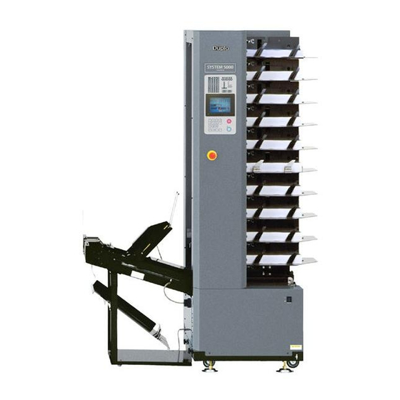
Page 16: Names And Operation Of Parts
Chapter1 Before Use Names and Operation of Parts [10] [22] [21] [23] [12] [11] [14] [13] [24] [19] [17] [18] [20] [16] [15]... - Page 17 Chapter1 Before Use Name Operation Control panel For details, refer to “3. Names and Operation of Control Panel” (p.1-4). Horizontal conveyance section Conveys the collated paper. Emergency stop switch Press this switch to stop operations in emergency. Normally, use the stop key on the control panel to stop operations.
-
Page 18: Names And Operation Of Control Panel
Chapter1 Before Use Names and Operation of Control Panel [16] [15] [14] [13] [12] [11] [10] Name Operation Paper lamp The lamp of the paper feed tray feeding paper lights up. When a paper feed tray runs out of paper, the corresponding lamp of the paper feed tray blinks and the machine stops. -
Page 19: Accessory Parts
Chapter1 Before Use Name Operation Tower error lamp The lamp of the corresponding tower lights up when the following occurs in that tower. •The vertical conveyance board is open. •The emergency stop switch is pressed. •There is no paper. •Paper feed errors occur. •Paper jams in the paper conveyance path. -
Page 20: Options
Chapter1 Before Use Options PC CONTROLLER Name Qty. Protection key CD-R unit Precautions on Use of Emergency Stop Switch Use the emergency stop switch to stop operations in emergency. In normal operations, use the stop key on the control panel to stop operations. Stopping operations using the emergency stop switch will light up the tower error lamp on the control panel of the tower whose switch was pressed. -
Page 21: Operation Procedures
Chapter 2 Operations Chapter 2 Operations Operation Procedures (p.2-2) Set at PC CONTROLLER (*1) Power On • Set paper ejection direction Adjusting the position of the (p.2-2) sub-guide • Set block mode (p.2-3) Adjusting the position of the reject tray stopper •... -
Page 22: Power On
Chapter 2 Operations Power On <When Connected> Check that the power switches of all the Main power switch Power switch towers are set to “ ”. Set the main power switches of all the towers to “I”. Set the power switch of Tower A to “I”. Set the power switch of Tower A to “... -
Page 23: Adjusting The Position Of The Reject Tray Stopper
Chapter 2 Operations 3-2. Adjusting the Position of the Reject Tray Stopper Move the position of the reject tray Reject tray stopper according to the paper size. Stopper 3-3. Adjusting the Height of the Level Sensor Make sure not to insert your hands inside the paper feed tray while the suction belt or conveyance shaft is driving. -
Page 24: Adjusting The Separating Air
Chapter 2 Operations 3-4. Adjusting the Separating Air Rotate the separating air adjustment to adjust the amount of the separating air. • The larger the number, the stronger the Separating-air adjusting knob separating air blown out will be. • The standard position of the separating air is “2”. -
Page 25: Adjusting The Strength Of Separating Air
Chapter 2 Operations 3-6. Adjusting the Strength of Separating Air Switch the separating-air adjusting lever according to the paper size and paper quality. When mis-feed occurs by using small paper or thin paper, turn the lever to the direction of “weak”. Separating-air adjusting lever “Strong”... -
Page 26: Loading The Paper
Chapter 2 Operations Loading the Paper 4-1. Precautions on Loading Paper • Thoroughly fan the paper before loading. Otherwise, problems such as double-feeding may occur. • Make sure that the printing ink on the paper is completely dry before loading. Otherwise, problems such as ink smearing (setoff ) and double-feeding may occur. -
Page 27: Loading Paper In Normal Collation Operations
Chapter 2 Operations 4-3. Loading Paper in Normal Collation Operations As an example, the following explains the process of collating 20 pages using two connected towers. A. When setting to eject paper to left side Load the paper sheets in descending page Tower A Tower B order from the paper feed tray 1 of Tower A as... -
Page 28: Loading Paper In Collation Operations With Cover Insertions
Chapter 2 Operations 4-4. Loading Paper in Collation Operations with Cover Insertions • Always load paper on consecutive paper feed trays. Otherwise, collating errors will occur and the machine will stop. • If paper is loaded only on one paper feed tray, the paper lamp blink. When using two towers or more, use more than two trays per tower. - Page 29 Chapter 2 Operations • When more than two towers are connected, Tower A Tower B load the covers on the paper feed trays above Page 9 the topmost tray paper of the first tower and Cover 2 below the bottommost tray paper of the last Page 1 connected tower.
- Page 30 Chapter 2 Operations D. Inserting two covers with paper ejection set to right side (When the cover 2 is set in the processing mode:) • Load the covers on the paper feed trays above the topmost tray paper and below the xx: No.
-
Page 31: Using The Paper Guide
Chapter 2 Operations Using the Paper Guide The paper loading direction differs according to the paper ejection direction, block mode, and processing mode. For further details, refer to the instruction manual of the PC CONTROLLER (optional). Load paper on the paper feed tray. Align the leading edge of the paper and load until it presses against the shutter lightly. - Page 32 Chapter 2 Operations • When feeding paper of A4 size (paper length: 300 mm/11.8 inches) or more, use the long stack guide. When the paper guide is used, separating air may escape on the way and may not blow the bottom part of the paper. •...
-
Page 33: Using The Extension Tray
Chapter 2 Operations 4-6. Using the Extension Tray Use the extension tray to process the paper of 508 mm / 20.0 inches or longer (*1). (*1) : The following paper length and width can be used. • Length: up to 610 mm / 24.0 inches •... -
Page 34: Pc Controller
Chapter 2 Operations PC CONTROLLER In this machine, the following items are set by the PC CONTROLLER. For operations of the PC CONTROLLER, refer to the operation manual of the PC CONTROLLER. 5-1. Making Basic Setting • Towers used • Paper Ejection Direction •... -
Page 35: Selecting The Paper Eject Direction
Chapter 2 Operations Selecting the Paper Eject Direction Set the paper ejection direction to the right side or left side. First tower First tower First tower First tower for processing for processing Right side ejection and left side ejection right side ejection left side ejection can not be processed simultaneously at the connected towers. -
Page 36: Functions Of Block Mode And Their Use
Chapter 2 Operations Functions of Block Mode and Their Use One of the block modes is called as “ALL” by which the paper feed trays of the towers are used without being divided. In the other block modes, the paper feed trays are divided into “1/2 block”, “1/3 block” and “1/4 block”... -
Page 37: Example Of Using The 1/3 Mode
Chapter 2 Operations Connection of five towers Each Booklet System No.1 No.1 No.2 No.1 No.2 No.2 DBMi Saddle System No.1 No.1 No.2 No.2 No.1 No.2 7-3. Example of Using the 1/3 Mode Paper feed trays are divided into two paper feeding blocks (No.1 and No.3) as shown in the figure. Connection of three towers No.1 No.2... -
Page 38: Example Of Using The 1/4 Mode
Chapter 2 Operations 7-4. Example of Using the 1/4 Mode Paper feed trays are divided into two paper feeding blocks (No.1 and No.4) as shown in the figure. Connection of two towers No.1 No.3 No.2 No.4 Connection of six towers Each Booklet System No.1 No.3... -
Page 39: Functions Of Processing Mode And Their Use
Chapter 2 Operations Functions of Processing Mode and Their Use The following five types of processing modes are available to collate paper. Select a processing mode suitable for use. (1) Normal Mode : Paper is fed from all paper feed trays with loaded paper. (2) Alternate Mode : Suitable to use for trayding paper with thick paper as a cover. -
Page 40: Alternate Mode
Chapter 2 Operations 8-2. Alternate Mode This mode is appropriate when using thick paper for the cover of bound set. • When setting to eject paper to the left side, of the paper feed trays stacked with paper, paper is fed from the topmost tray or the tray below. -
Page 41: Interleaf Mode
Chapter 2 Operations 8-3. Interleaf Mode Interleaf When collating general printed matter, insert paper which will serve as an indication that a certain number of sets have been collated, so as to improve the efficiency of downstream binding processes. This sheet of paper inserted halfway through is called “cover”. -
Page 42: Collation
Chapter 2 Operations Collation 9-1. Checking the Paper Feeding Check that the paper is fed normally after setting the paper ejection direction, program mode, block mode, and cover insert mode on PC CONTROLLER (optional). Press key for about one second to collate one set. -
Page 43: Start/Stop Of Collation
Chapter 2 Operations When mis-detection occurs Double-feed or miss-feed may sometimes be detected although the paper is fed normally. • If mis-detection of double-feed occurs with the double-feed detection function set to thin paper, set it to thick paper and perform preset again. If double-feed occurs even when set to thick paper, it means that the double-feed detection function cannot be used for the paper. -
Page 44: Waiting Mode
Chapter 2 Operations 10. Waiting Mode The waiting mode is used to standby keeping the paper feeding conditions without stopping the machine, when a problem has occurred or under certain conditions. 10-1. When the Waiting Mode is Activated The waiting mode is activated differently according to the setting details of PC CONTROLLER. For further details, refer to the instruction manual of PC CONTROLLER. -
Page 45: Canceling Waiting Mode
Chapter 2 Operations 10-2. Canceling Waiting Mode 1. Stop the machine completely. Press key. 2. Restart the machine. Press key. When the waiting mode is activated due to double-feed or mis-feed, press the start key after checking paper on the related paper feed tray. -
Page 46: Double-Feed Detection Function
Chapter 2 Operations 11. Double-Feed Detection Function 11-1. What is Double-Feed Detection Function ? Double-feed is feeding of more than two sheets of paper at once time. Using a sensor which measures paper thickness, the thickness of a paper fed is read as standard data during presettings, this paper is then compared with the data of the paper conveyed from the paper feed trays, and if the difference between the two data is large, it is determined as double-feeding of paper. -
Page 47: Using The Lul-Hm
Chapter 2 Operations 12. Using the LUL-HM The LUL-HM is a device for feeding paper sets containing several sheets (below 10 sheets) by hand marry or hand feed. It can be used only when paper ejection is set to the left side. 12-1. -
Page 48: Hand Feed
Chapter 2 Operations A. Adjusting the mix timing If the timing of the paper set from the hand marry does not match the timing for merging the set from the tower and as a result causes poor paper alignment, adjust the mix timing at option menu 2 on the touch panel. -
Page 49: Troubleshooting
Chapter 3 Troubleshooting Chapter 3 Troubleshooting When Monitor Lamp Lights Up The control panel has monitor lamps indicating the location where problems have occurred. When a monitor lamp lights up, perform the corresponding procedure below. 1-1. When the Door Error Lamp Lights Up The door error lamp lights up when the conveyance Door error lamp board either of the vertical conveyance section, LUL-... -
Page 50: When The Conveyance Path Jam Lamp Lights Up
Chapter 3 Troubleshooting 1-2. When the Conveyance Path Jam Lamp Lights Up Check which tower’s tower error lamp is Tower error lamp lit. Paper has jammed in the vertical conveyance section or horizontal conveyance section of this tower. Conveyance path If this tower is the first tower, paper has jam lamp jammed in the conveyance section of the LUL-... - Page 51 Chapter 3 Troubleshooting (4) When paper has jammed at the LUR Conveyance board Lift the conveyance board and remove the jammed paper. Close the conveyance board completely. Otherwise, the machine will not start. Paper...
-
Page 52: When The Double-Feed, Mis-Feed, And Jam Lamps Blink Simultaneously
Chapter 3 Troubleshooting 1-3. When the Double-Feed, Mis-Feed, and Jam Lamps Blink Simultaneously The suction box has been pressed up by a foreign object and paper. Remove the foreign object which has pressed up the suction box referring to the following procedures, and adjust the level sensor. -
Page 53: Countermeasures Taken For Jam At Paper Feed Inlet
Chapter 3 Troubleshooting Countermeasures Taken for Jam at Paper Feed Inlet Take the following countermeasures when paper jams at the paper feed inlet. Press the eject key keeping tray down key pressed. The paper feed belt rotates reversely and the jammed paper is returned. Check that the paper feed tray and paper feed belt have stopped and remove the paper. -
Page 54: Troubleshooting Guide
Chapter 3 Troubleshooting Troubleshooting Guide Symptoms Causes Countermeasures Power supply is not The power code is removed. Connect the power cord securely. (p.2-2) turned on The main power switch is not turned ON. Turn ON the main power switch of all the towers connected. - Page 55 Chapter 3 Troubleshooting Symptoms Causes Countermeasures Paper is mis-fed The level sensor is adjusted defectively. Raise higher the position of the level sensor. (p.2-3) The separating air is adjusted defectively. Adjust the amount of separating air blown out by using the separating-air adjusting knob.
- Page 56 Chapter 3 Troubleshooting Symptoms Causes Countermeasures Double-feed is mis- Preset operations are not performed. •Be sure to perform preset operations when detected. paper is replaced and loaded. •Perform preset operations again if mis- feed or double-feed occurs at preset operations. (p.2-22) Double-feed detection is not set appropriately.
-
Page 57: Cleaning The Machine
Chapter 4 Cleaning the Machine Chapter 4 Cleaning the Machine Cleaning Parts Before cleaning, be sure to turn OFF the power. • Clean the conveyance belts and conveyance rollers once a day. • Problems may result if they are dirty. To clean, moisten a cloth with water or alcohol, and wipe the dirty part. -
Page 58: Cleaning The Cconveyance Belt Of The Horizontal Conveyance Section
Chapter 4 Cleaning the Machine 1-3. Cleaning the Cconveyance Belt of the Horizontal Conveyance Section Clean while rotating the conveyance belt by hand. Conveyance belt 1-4. Cleaning the Conveyance Belt of the LUL-HM Clean while rotating the conveyance belt by hand. Conveyance belt... -
Page 59: Double-Feed Sensor
Chapter 4 Cleaning the Machine 1-5. Double-Feed Sensor Blow air through the vent hole to clean the sensor. - Page 60 Memo Chapter 4 Cleaning the Machine...
-
Page 61: Appendix
Chapter 5 Appendix Chapter 5 Appendix Specifications Model DSC-10/60 Type Floor type vertical collator The number of trays to 10 trays/tower be collated Maximum number of units connectable Feeding system Belt suction feed system Conveyance system Roller belt conveyance system Maximum paper 65 mm / 2.56 inches in height loading volume... - Page 62 Chapter 5 Appendix Airborne noise • Single tower with LUL-HM, left side ejection Equivalent continuous A-weighted sound pressure level: 74.8 dB Sound pressure level: 90.7 dB (including the peak) • Measurement condition: Using fine quality paper (81.4 g/m ), A4 LEF direction, feeding from all trays, process speed 4000 sets/h.
- Page 63 Memo...
- Page 64 4-1-6 Oyama, Chuo-ku, Sagamihara-shi, Kanagawa 252-5280, Japan TEL: +81-42-775-3602 FAX: +81-42-775-3606 E-mail: info@duplo.com This manual is printed on recycled paper to help protect the environment. 15G-90022-0 12110000D...
Need help?
Do you have a question about the DSC-10/60i and is the answer not in the manual?
Questions and answers