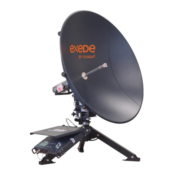
ViaSat SurfBeam 2 Manual
Point and peak job aid
Hide thumbs
Also See for SurfBeam 2:
- Operation manual (66 pages) ,
- Manual (5 pages) ,
- Installation manual (58 pages)
Advertisement
Quick Links
75cm ODU/SurfBeam 2 Point and Peak Job Aid
Summary
This Job Aid covers:
Preparing the Antenna for Pointing and Peaking
Configure the SurfBeam 2 Modem and 75cm TRIA
Point Elevation
Set the Skew
Point Azimuth
Peak Azimuth
Peak Elevation
Push/Pull Test
RX SNR in the Modem Browser Interface
This Job Aid supports all Installer audiences.
This Job Aid supports all 75cm SurfBeam 2 User Terminals: VS1100, VS1101, VS1200, and VS1300.
Note: Images for the VS1100 appear on the left; images for the VS1200/VS1300 appear on the right.
Preparing the Antenna for Pointing and Peaking
The following information reviews the steps necessary to prepare the satellite modem and the Ka-band
antenna to support the ViaSat Point and Peak process. The installer is required to complete this process
during every ViaSat Service installation.
Warning:
Confirm that the modem is unplugged from the wall before beginning any preparation
steps.
Setting 'Zero'
Before aligning an antenna, confirm that these items are present. These three settings represent the 'zero'
settings.
The Elevation gauge is set to the Elevation listed on the work order
The Azimuth Fine-adjust bolt is centered in its 'zero' position.
o VS1100: If not, loosen the Azimuth base plate bolts, and rotate the bolt's hex head until the
right-rear base plate bolt is in the center of its arched slot.
o VS1200/ VS1300: If not, loosen the Azimuth base plate bolts, turn the Fine Azimuth adjustment
nut until the indicators on the base of the AZ/EL are at Zero (0).
The Skew is set for 90 degrees
© 2006 - 2014 ViaSat, Inc.
Release Date: November 2014
Page
1
of
12
Proprietary – For use only pursuant to
company approval and instructions
Terms of
use.
Advertisement

Summary of Contents for ViaSat SurfBeam 2
- Page 1 Preparing the Antenna for Pointing and Peaking The following information reviews the steps necessary to prepare the satellite modem and the Ka-band antenna to support the ViaSat Point and Peak process. The installer is required to complete this process during every ViaSat Service installation.
- Page 2 These steps assume that the 75cm ODU is sitting on its mount, and that cabling and grounding are complete. Follow these steps to configure the SurfBeam 2 modem and 75cm TRIA prior to beginning the Point and Peak process.
- Page 3 75cm ODU/SurfBeam 2 Point and Peak Job Aid Release Date: November 2014 Step Action (continued) Open the computer’s Internet Explorer browser and type this URL into the Address bar: http://192.168.100.1/install Click the forward arrow in the Address bar. The modem enters the Installation Mode.
- Page 4 75cm ODU/SurfBeam 2 Point and Peak Job Aid Release Date: November 2014 Point Elevation The following information reviews the steps to complete the point (coarse) antenna Elevation adjustment. Step Action Slightly loosen the Lockdown Nuts in the Arched Slots on sides of the Elevation Bracket.
- Page 5 75cm ODU/SurfBeam 2 Point and Peak Job Aid Release Date: November 2014 Step Action (continued) Use the open wrench to turn the Bottom Nut in the direction necessary to align the Inclinometer floating arrow to the marker. Handtighten the top nut on the Elevation rod to the Pivot Casting. Finally, tighten the Lockdown Nuts in the Arched Slots on each side of the Elevation Bracket with the open wrench or ratchet.
- Page 6 75cm ODU/SurfBeam 2 Point and Peak Job Aid Release Date: November 2014 Step Action (continued) Rotate the reflector dish so that the Skew pointer aligns with the Skew setting on the scale. Tighten the four bolts. Point Azimuth Point the antenna to the course azimuth.
- Page 7 75cm ODU/SurfBeam 2 Point and Peak Job Aid Release Date: November 2014 Follow these steps to point the Azimuth of the 75cm ODU. Step Action Sweep the antenna from side to side, checking the tightness of the three flange nuts on the mount canister.
- Page 8 75cm ODU/SurfBeam 2 Point and Peak Job Aid Release Date: November 2014 Step Action (continued) Finish this step by tightening the Flange bolts, starting with the top to maintain an even pressure on the Tube canister. Note: The high/steady tone may dip while tightening the Flange bolts. If the tone does not return to the high/steady, then repeat the step.
- Page 9 75cm ODU/SurfBeam 2 Point and Peak Job Aid Release Date: November 2014 Step Action (continued) Sweep the antenna toward the left, listening for the TRIA to emit the low/slow tone, which means that the antenna has found the far edge of its frequency set.
- Page 10 75cm ODU/SurfBeam 2 Point and Peak Job Aid Release Date: November 2014 VS1100: Damaging the Azimuth Fine-adjust Bolt If the Azimuth Fine-adjust bolt is not centered prior to beginning the Point and Peak process with the VS1100 ODU, the peaking procedure may cause unwelcome stress where the Fine-adjust bolt attaches to the Azimuth base plates.
- Page 11 75cm ODU/SurfBeam 2 Point and Peak Job Aid Release Date: November 2014 Step Action (continued) Sweep the nut on the Elevation rod such that the TRIA drops ,and listen for the TRIA to emit the low/slow tone, which means that the antenna has found the far edge of its frequency set.
- Page 12 75cm ODU/SurfBeam 2 Point and Peak Job Aid Release Date: November 2014 Push/Pull Test Important: An installer always completes two tests before obtaining Modem Lock: a Push/Pull test and a review of the RX SNR in the Signal Strength section of the Modem Browser Interface.


Need help?
Do you have a question about the SurfBeam 2 and is the answer not in the manual?
Questions and answers