ViaSat SurfBeam 2 Operation Manual
Pro portable terminal
Hide thumbs
Also See for SurfBeam 2:
- Manual (12 pages) ,
- Manual (5 pages) ,
- Installation manual (58 pages)
Table of Contents
Advertisement
SurfBeam® 2
Pro Portable Terminal
Operations Guide
ViaSat Document No.: 1172964
(Rev. 002)
Prepared by:
ViaSat, Inc.
6155 El Camino Real
Carlsbad, CA 92009-1699
Tel: (760) 476-2200
Fax: (760) 929-3941
www.viasat.com
This technical data is subject to the United States Export Administration Regulations.
Diversion contrary to U.S. law is prohibited. ViaSat proprietary information.
Advertisement
Table of Contents

Related Manuals for ViaSat SurfBeam 2


Summary of Contents for ViaSat SurfBeam 2
- Page 1 Prepared by: ViaSat, Inc. 6155 El Camino Real Carlsbad, CA 92009-1699 Tel: (760) 476-2200 Fax: (760) 929-3941 www.viasat.com This technical data is subject to the United States Export Administration Regulations. Diversion contrary to U.S. law is prohibited. ViaSat proprietary information.
- Page 2 ViaSat Proprietary – Information, specifications, and features contained in this document are subject to change without notice and should not be construed as a commitment by ViaSat Inc. This document is proprietary to ViaSat Inc. and shall be protected by a receiving party in accordance with the terms of its contracts and agreements with ViaSat Inc., covering SurfBeam®2 and ViaSat...
- Page 3 SurfBeam® 2 Pro Portable Terminal Operations Guide BOUT THIS OCUMENT This guide covers key aspects of the SurfBeam 2 Pro Portable’s hardware/software descriptions, installation, configuration, and troubleshooting. This guide is segmented into the following main sections: Section 1 Introduction Section 2 Setup and Teardown...
- Page 4 PLL ........Phase Locked Loop RF ........Radio Frequency - R - RMA ........Return Material Authorization Rx........Receive SB2 ........SurfBeam 2 - S - SNR ........Signal to Noise Ratio TRIA ........Transmit Receive Integrated Assembly - T - Tx ........
-
Page 5: Table Of Contents
Appendix A SurfBeam 2 Pro Portable Specifications ......................A-1 Appendix B SurfBeam 2 Pro Portable Quick Start Guide ..................... B-1 Appendix C SurfBeam 2 Pro Portable Field Service Bulletin(s) .................... C-1 Pro Portable Single and Dual Co-Pol TRIA ............................. C-1 ©... - Page 6 Table C-1: Configuration 1 – Polarization Identification ................................C-4 Table C-2: Configuration 2 – Polarization Identification ................................C-7 List of Figures Figure 1-1: SurfBeam 2 Pro Portable ....................................... 1-1 Figure 2-1: Antenna Transporting Restrictions ..................................2-3 Figure 2-2: Modem Assembly Transporting Restrictions ................................. 2-3 Figure 2-3: Component Assembly Layers ....................................
-
Page 7: Introduction
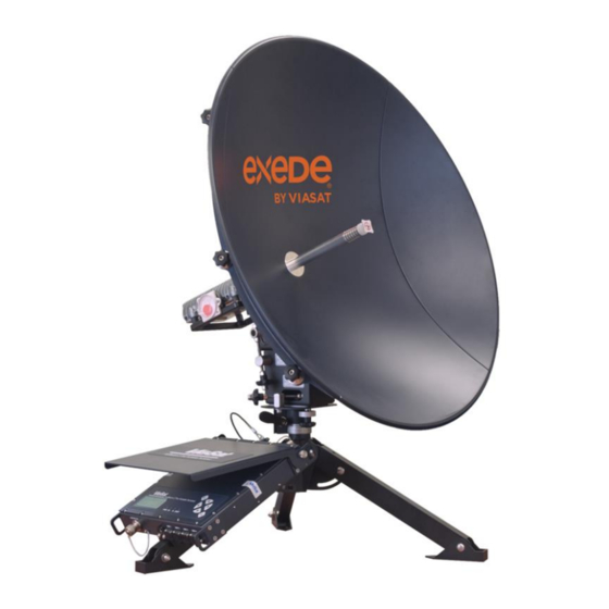
SurfBeam® 2 Pro Portable Terminal Operations Guide NTRODUCTION The ViaSat SurfBeam 2 (SB2) Pro Portable Terminal (Figure 1-1) provides portable and quickly deployable, high-speed internet and network connections in remote regions. The unit supports live video, file transfer, internet browsing and more. -
Page 8: Terminal Setup And Teardown
ETUP AND EARDOWN The SurfBeam 2 Pro Portable Terminal can be deployed in just about any desired location. To ensure optimal performance, all the installer must do is identify a stable deployment location with an unobstructed view of the sky and properly assemble the unit. -
Page 9: Receiving, Unpacking, And Assembly
This is important if a damage claim must be filed. CAUTION: Do not attempt to operate the equipment if major damage is found. In the event questionable damage (major or otherwise) is identified, contact ViaSat, Inc. for support. 2.3.1.2 Handling and Precautions CAUTION: Proper ESD precautions shall be maintained when handling equipment. -
Page 10: Figure 2-1: Antenna Transporting Restrictions
The assembly shall only be carried or moved by using two hands (one hand on each side) and never by any connected cable. Observe the handling restrictions shown in Figure 2-2 for proper handling and transportation. Figure 2-2: Modem Assembly Transporting Restrictions © 2014 ViaSat, Inc. All Rights Reserved Page 2-3 1172964, Rev. -
Page 11: Unpacking
The edge reflector provides the edge piece of the (x2) antenna dish and mounts to either side of the center reflector. These two parts are interchangeable. © 2014 ViaSat, Inc. All Rights Reserved Page 2-4 1172964, Rev. 002 ViaSat Proprietary Information... - Page 12 The Power cable for the Power Supply Brick is common three-wire cable. 90° Coax The 90° coax connector is designed to modify a Connector straight RG6 F-type cable connection. © 2014 ViaSat, Inc. All Rights Reserved Page 2-5 1172964, Rev. 002 ViaSat Proprietary Information...
-
Page 13: Assembling
Remove the Azimuth/Elevation Assembly from the pocket on the left side of the case. Looking at the base of the Assembly, loosen the Azimuth lever and knob. © 2014 ViaSat, Inc. All Rights Reserved Page 2-6 1172964, Rev. 002 ViaSat Proprietary Information... - Page 14 If it does not, rotate the top-plate to its bottom position and rotate the Elevation Fine Adjusting knob until the line on the top-plate lines up with the 0° marker on the tower. © 2014 ViaSat, Inc. All Rights Reserved Page 2-7 1172964, Rev. 002...
- Page 15 Remove the Assembly, go to the transit case, and fold open the two pockets that held the Assembly and Tripod to gain access to the Center Reflector. © 2014 ViaSat, Inc. All Rights Reserved Page 2-8 1172964, Rev. 002...
- Page 16 Mount the Assembly to the back of the Reflector using the four attached screws (hand-tighten these screws only), where the top of the Assembly points to the ViaSat logo. Remove the Reflector and Assembly from the case, and slide the Assembly onto the Tripod’s post and rotate it to ensure proper...
- Page 17 Splash Plate is properly seated on the Feedhorn. At the transit case, fold back the layer two and three dividers and CAREFULLY remove the modem assembly. © 2014 ViaSat, Inc. All Rights Reserved Page 2-10 1172964, Rev. 002...
- Page 18 Connect one end of the 3ft RG6 Coax cable to the “Antenna” port on the back of the modem assembly and connect the other end with the 90° connector fitting to the “TX” port on the TRIA. © 2014 ViaSat, Inc. All Rights Reserved Page 2-11 1172964, Rev.
- Page 19 OFF position (down) to the ON position (up). Open the lid of the modem assembly and use the tightening screws on either side to lock it in the desired position. © 2014 ViaSat, Inc. All Rights Reserved Page 2-12 1172964, Rev.
-
Page 20: Disassemble And Repack
SurfBeam® 2 Pro Portable Terminal Operations Guide 2.4 Disassemble and Repack The SurfBeam 2 Pro Portable Terminal will need to be stowed after each use. Table 2-3 provides the instructions on this process. Table 2-3: Disassembly and Repacking Process Step... - Page 21 Unscrew and detach the Edge Reflectors (pulling/wiggling) and place them back into the case. NOTE: Ensure the protective felt divider covers the top of the edge reflectors after being placed in the case. © 2014 ViaSat, Inc. All Rights Reserved Page 2-14 1172964, Rev. 002...
- Page 22 Verify that the Assembly base-plate and tower edges are approximately parallel. If they are not, rotate the Azimuth Fine Adjusting knob until the two edges become parallel. © 2014 ViaSat, Inc. All Rights Reserved Page 2-15 1172964, Rev. 002...
- Page 23 Confirm that all cables are in the case pouch and zip it closed, close the case top, and ensure the lid lock-down latches are secure. © 2014 ViaSat, Inc. All Rights Reserved Page 2-16 1172964, Rev. 002...
-
Page 24: Terminal Satellite Aligning
The Beep-Bop tone indicates two modem states: When the TRIA locates a satellite with Ka-Band frequencies that the modem does not recognize When the modem has reset during a re-Pointing process. © 2014 ViaSat, Inc. All Rights Reserved Page 3-1 1172964, Rev. 002... -
Page 25: Modem Setup
Use arrow keys to scroll to “→ Press ENT to Cont.” menu item and press ENT button and continue with section 3.3, Baseline Elevation and Azimuth Setup. © 2014 ViaSat, Inc. All Rights Reserved Page 3-2 1172964, Rev. 002... -
Page 26: Baseline Elevation And Azimuth Setup
Inclinometer to equal the “EL” value shown on the “Status” screen. NOTE: This may take many turns to make a fine movement. © 2014 ViaSat, Inc. All Rights Reserved Page 3-3 1172964, Rev. 002... - Page 27 “Low/Slow” or a “High/Fast” tone, use the “EL Fine Adjust” knob to raise or lower the TRIA angle (a degree at a time) until the you hear one of the two tones. © 2014 ViaSat, Inc. All Rights Reserved Page 3-4 1172964, Rev.
-
Page 28: Fine-Tuning Azimuth And Elevation Setup
Tighten the two “Lock AZ Angle” knobs on the base plate so the antenna has no movement left or right. NOTE: If you lose the tone while tightening; loosen them and repeat the above steps. © 2014 ViaSat, Inc. All Rights Reserved Page 3-5 1172964, Rev. 002... - Page 29 Open a web browser window and type 192.168.100.1 into the address bar and verify you can access the modem’s web interface. © 2014 ViaSat, Inc. All Rights Reserved Page 3-6 1172964, Rev. 002...
-
Page 30: Modem Relocation
“→”. NOTE: If the display shows a checkerboard pattern (a screen saver), press any of the four Arrow Keys to continue.. © 2014 ViaSat, Inc. All Rights Reserved Page 3-7 1172964, Rev. 002... - Page 31 Open a web browser window and type 192.168.100.1 into the address bar and verify you can access the modem’s web interface by selecting “Modem” in the menu tree on the left. © 2014 ViaSat, Inc. All Rights Reserved Page 3-8 1172964, Rev.
-
Page 32: Terminal Operations
ERMINAL PERATIONS The SurfBeam 2 Pro Portable modem uses an LCD screen and a web interface to provide valuable operational and status information regarding the modem, antenna, and installation configuration. The following sections provide details regarding accessing and navigating the modem’s LCD screen and web interface. -
Page 33: Modem Web Interface
Once accessed, the web browser will open the modem’s “Home” page (Figure 4-3). From this page, the user can access general information for the modem and TRIA configuration/status. Figure 4-3: Modem Web Interface © 2014 ViaSat, Inc. All Rights Reserved Page 4-2 1172964, Rev. -
Page 34: Table 4-1: Operational Beam
Contact the NOC if the first several attempts did not correct the issue Fault Red = Indicates a fault has been detected or there is no communication’s link. © 2014 ViaSat, Inc. All Rights Reserved Page 4-3 1172964, Rev. 002... -
Page 35: Figure 4-4: Modem Web Interface - Home Page
IFL page. TRIA: Displays the antenna’s current operating state. Clicking on the “TRIA” label below the box displaying the antenna and the state icon, will navigate to the TRIA page. © 2014 ViaSat, Inc. All Rights Reserved Page 4-4 1172964, Rev. -
Page 36: Figure 4-5: Modem Web Interface - Modem Page
Modem Page (Modem/IFL Cable Status) The Modem page (Figure 4-5) provides general information on the status of the modem, Inter-Facility Link (IFL), and antenna. Figure 4-5: Modem Web Interface – Modem Page © 2014 ViaSat, Inc. All Rights Reserved Page 4-5 1172964, Rev. 002... - Page 37 Loss of Sync Count: Counts the number of sync losses for the current connection. Transmitted Bytes: Displays the number of bytes transmitted to the modem. Received Bytes: Displays the number of bytes received by the modem. © 2014 ViaSat, Inc. All Rights Reserved Page 4-6 1172964, Rev.
-
Page 38: Figure 4-6: Modem Web Interface - Tria Page
TRIA Firmware Version: Displays the TRIA’s firmware version. Module Status Bullfrog VG, Watchdog Timer, Tx/Rx PLL, Microprocessor, Cable Resistance, and Temperature: Displays depending on if the system has detected an issue. © 2014 ViaSat, Inc. All Rights Reserved Page 4-7 1172964, Rev. 002... -
Page 39: Router Web Interface
Once accessed, the web browser will open the router’s “Home” page (Figure 4-8). From this page, the user can access general information for the router configuration/status. Figure 4-8: Router Web Interface © 2014 ViaSat, Inc. All Rights Reserved Page 4-8 1172964, Rev. -
Page 40: Figure 4-9: Router Web Interface - System Status Page
The System Status page (Figure 4-9) provides general information on the status of the modem/router, Firmware version, and connection activity. Figure 4-9: Router Web Interface – System Status Page © 2014 ViaSat, Inc. All Rights Reserved Page 4-9 1172964, Rev. 002... -
Page 41: Figure 4-10: Router Web Interface - Router Status Page
The Router Status page (Figure 4-10) provides general information on the status of the router’s WAN, DNS, LAN, DHCP, and the router’s serial/part numbers. Figure 4-10: Router Web Interface – Router Status Page © 2014 ViaSat, Inc. All Rights Reserved Page 4-10 1172964, Rev. -
Page 42: Figure 4-11: Router Web Interface - Lan Setup Page
The DHCP Setup page (Figure 4-12) provides the ability to add static IP addresses and view general information on any current configured static IP address. Figure 4-12: Router Web Interface – DHCP Setup Page © 2014 ViaSat, Inc. All Rights Reserved Page 4-11 1172964, Rev. -
Page 43: Figure 4-13: Router Web Interface - Port Forwarding Page
Range Forwarding Page The Range Forwarding page (Figure 4-14) provides general information and the ability to add/configure/remove ports for Range Forwarding. Figure 4-14: Router Web Interface – Range Forwarding Page © 2014 ViaSat, Inc. All Rights Reserved Page 4-12 1172964, Rev. 002... -
Page 44: Figure 4-15: Router Web Interface - Dmz Page
Figure 4-15: Router Web Interface – DMZ Page 4.3.2.3.4 Routes Page The Routes page (Figure 4-16) provides information on the current routing table. Figure 4-16: Router Web Interface – Routes Page © 2014 ViaSat, Inc. All Rights Reserved Page 4-13 1172964, Rev. 002 ViaSat Proprietary Information... -
Page 45: Figure 4-17: Router Web Interface - Password Page
4.3.2.4.2 Backup/Restore Page The Backup/Restore page (Figure 4-18) provides the ability backup, load new, or restore the modem’s configuration. Figure 4-18: Router Web Interface – Backup/Restore Page © 2014 ViaSat, Inc. All Rights Reserved Page 4-14 1172964, Rev. 002 ViaSat Proprietary Information... -
Page 46: Figure 4-19: Router Web Interface - Firmware Upgrade Page
4.3.2.4.4 Reboot Page The Reboot page (Figure 4-20) provides the ability to perform a router reboot from the web interface. Figure 4-20: Router Web Interface – Reboot Page © 2014 ViaSat, Inc. All Rights Reserved Page 4-15 1172964, Rev. 002... -
Page 47: Figure 4-21: Router Web Interface - Utilities Page
The Utilities page (Figure 4-21) provides the ability to test network connectivity by Pinging specific devices or web sites and performing a Trace Route. Figure 4-21: Router Web Interface – Utilities Page © 2014 ViaSat, Inc. All Rights Reserved Page 4-16 1172964, Rev. -
Page 48: Firmware Update
Table 4-3: Router Firmware Update Process Step Action Image Contact ViaSat for the latest firmware images and source code at: exedeenterprisesupport@viasat.com After receiving the firmware release, save it to an easily accessible location on a user provide computer. Power ON the modem assembly. -
Page 49: Network Connectivity
Yahoo.com, MSN.com, and Google.com to verify that a connection has been established. NOTE: If no connection is established, clear the cache and cookies from the browser Internet options and attempt to reconnect. © 2014 ViaSat, Inc. All Rights Reserved Page 4-18 1172964, Rev. -
Page 50: Terminal Maintenance
Routine inspections and maintenance of the equipment are critical to the operation and long life of the equipment. Perform the following inspections and document any findings (photos are preferred). Submit any findings and photos to ViaSat customer service with serial number for engineering review. The modem assembly is an LRU and is typically not field repairable. - Page 51 90° Coax Adapter 1156729 NOTE: The SurfBeam 2 Pro Portable Terminal does not have any field replaceable parts. If any part is missing from the case, refer to section 7 for additional assistance. Remove and inspect the laminated “Quick Setup Guide”...
-
Page 52: Fielded Daily Maintenance And Inspection
Check all wiring and coaxial cables for cuts, nicks, burns, or abraded insulation; bare or damaged wires; sharp V bends; pinched wires; broken or loose lacing, tie wraps, and clamps © 2014 ViaSat, Inc. All Rights Reserved Page 5-3 1172964, Rev. -
Page 53: Troubleshooting
The following outlines potential issue a user might come across while setting up, configuring, and operating the SurfBeam 2 Pro Portable system. Table 6-1 provides a list of potential hardware issues and the possible solutions. If the provided solution does not resolve the issue, contact ViaSat’s NOC. -
Page 54: Helpdesk Support
The customer is responsible for selecting the appropriate first point of contact that is the service provider from which the service was purchased. This may be either ViaSat directly or a Service Reseller (customer is responsible for obtaining the reseller contact information). -
Page 55: Reshipment
SurfBeam® 2 Pro Portable Terminal Operations Guide ESHIPMENT To ship the unit to another location, or return the unit to ViaSat for service/repair, use the carton(s) saved during the unpacking procedure. Place your contact information inside the container in case the package is lost or misdirected during shipping. -
Page 56: Appendix A Surfbeam 2 Pro Portable Specifications
RG6 linear compression connector type (No crimp connectors) Connector Requirements: Fully weather sealed CAT5 Ethernet Cable: The SurfBeam 2 Pro Portable Terminal will come with a 5-foot CAT5 Ethernet cable GPS: Single port 15 foot GPS cable Power Requirements Connection Type: 6 pin port connection with screw on feature for a secure connection ... - Page 57 Input Power: 220 Watts On/Off switch Auxiliary power output port Power input port RF connector Connector: Standard GPS connector © 2014 ViaSat, Inc. All Rights Reserved Page A-2 1172964, Rev. 002 ViaSat Proprietary Information...
-
Page 58: Appendix B Surfbeam 2 Pro Portable Quick Start Guide
Wait for “Long” and “Lat” screen to appear, scroll down the list, and press “Enter.” Set coarse elevation to the value listed on the LCD display, and then lock the antenna dish down. © 2014 ViaSat, Inc. All Rights Reserved Page B-1 1172964, Rev. - Page 59 Foundation Inc., 51 Franklin Street, Fifth Floor, Boston, MA 92110-1301 USA. In compliance with GPL V 2, copies of the modified source code for OpenWrt may be requested in writing by contacting ViaSat, Inc., attn: General Counsel / Source Code Request, 6155 El Camino Real, Carlsbad CA 92009 USA. Your request should clearly identify the product and open source software component(s) to which your request relates.
-
Page 60: Pro Portable Single And Dual Co-Pol Tria
Current documentation for the Pro Portable does not provide instructions on the following: Beam identification and Co-Pol TRIA modification/selection Configuration 1 installation instructions Configuration 2 installation instructions © 2014 ViaSat, Inc. All Rights Reserved Page C-1 1172964, Rev. 002 ViaSat Proprietary Information... -
Page 61: Figure C-1: Kacst Pro Portable Polarization Identification Map
The KACST program has designed the following map to identify the beam coverage areas and the polarization of those beams (refer to Figure C-1). Figure C-1: KACST Pro Portable Polarization Identification Map © 2014 ViaSat, Inc. All Rights Reserved Page C-2 1172964, Rev. -
Page 62: Figure C-2: Beam Selection For Identifying The Correct Co-Pol Tria
Identify the circle type (blue with diagonal lines or red without lines) where the location falls within the circle’s perimeter Use the identified circle type and the “Map Key” to identify the associated polarization © 2014 ViaSat, Inc. All Rights Reserved Page C-3 1172964, Rev. -
Page 63: Table C-1: Configuration 1 - Polarization Identification
Identify and/or mark the step number, as it will only refer to the unit having a single Co-Pol TRIA NOTE: See step 7 of the “Unpack and Assembly” section of the SurfBeam 2 Pro Portable Terminal manual released in September 2012. -
Page 64: Figure C-4: Uninstalling Feedhorn
Figure C-4: Uninstalling Feedhorn Rotate the Feedhorn 90 degrees so the markings on the unit match those identified in step 5 (refer to Figure C-5) Figure C-5: Rotating Feedhorn © 2014 ViaSat, Inc. All Rights Reserved Page C-5 1172964, Rev. 002... -
Page 65: Figure C-6: Reinstalling Feedhorn
Install the four hex screws on the base of the Feedhorn (torque screws to 35.6 kgf-cm (30.0 in-lbs)) (refer to Figure C-6) Figure C-6: Reinstalling Feedhorn 10. Continue with the “Unpack and Assembly” instructions provided with the unit © 2014 ViaSat, Inc. All Rights Reserved Page C-6 1172964, Rev. -
Page 66: Table C-2: Configuration 2 - Polarization Identification
Identify and/or mark the step number, as it will only refer to the unit having a single Co-Pol TRIA NOTE: See step 7 of the “Unpack and Assembly” section of the SurfBeam 2 Pro Portable Terminal manual released in September 2012.
Need help?
Do you have a question about the SurfBeam 2 and is the answer not in the manual?
Questions and answers