
Related Manuals for Teknik Executive Trestle Desk 5424128


Summary of Contents for Teknik Executive Trestle Desk 5424128
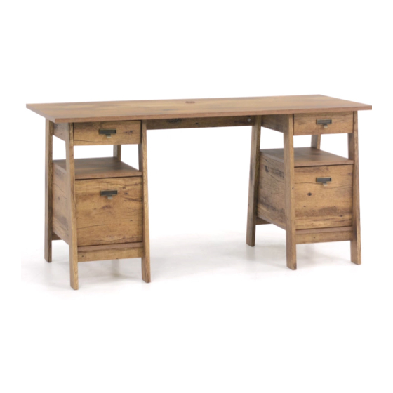
- Page 1 Teknik www.teknikoffice.co.uk Business or pleasure. Works both ways. Executive Trestle Desk | Model 5424128...
- Page 2 Table of Contents Assembly Tools Required Part Identifi cation No. 2 Phillips Screwdriver Tip Shown Actual Size Hardware Identifi cation Assembly Steps 6-28 Hammer Not actual size Français 29-32 Español 33-36 Skip the power trip. Safety 37-38 This time. Warranty Page 2...
-
Page 3: Part Identification
Now you know Part Identifi cation our ABCs. å While not all parts are labeled, some of the parts will have a label or an inked letter on the edge to help distinguish similar parts from each other. Use this part identifi cation to help identify similar parts. UPPER RIGHT END (2) D151 LARGE DRAWER BACK (2) -
Page 4: Hardware Identification
Hardware Identifi cation å Screws are shown actual size. You may receive extra hardware with your unit. RIGHT CABINET LEFT CABINET RIGHT DRAWER LEFT DRAWER RAIL - 2 RAIL - 2 SLIDE - 2 SLIDE - 2 (EXTENSION SET SHOWN SEPARATED) EXTENSION RAIL - 4 EXTENSION SLIDE - 4 35MA... - Page 5 Hardware Identifi cation å Screws are shown actual size. You may receive extra hardware with your unit. BLACK 9/16" LARGE HEAD SCREW - 24 BLACK 1-7/8" FLAT HEAD SCREW - 12 3S GOLD 5/16" FLAT HEAD SCREW - 32 BLACK 1-1/8" PAN HEAD SCREW - 16 30S BLACK 1-9/16"...
- Page 6 Step 1 Assemble your unit on a carpeted fl oor or on the empty å carton to avoid scratching your unit or the fl oor. To begin assembly, push a SAUDER TWIST-LOCK® å FASTENER (12F) into the large holes in the BACKS (H and J). Do not tighten the TWIST-LOCK®...
- Page 7 Step 2 Push twenty-four HIDDEN CAMS (1F) into the ENDS (A, B, å C2, and D2) and LOWER BACKS (I2). Then, insert the metal end of a CAM DOWEL (2F) into each HIDDEN CAM. NOTE: There are two of each of these parts (A, B, C2, D2, and I2). å...
- Page 8 Step 3 Push the remaining eighteen HIDDEN CAMS (1F) into the å BOTTOMS (F), SHELVES (G), and LARGE BACK (H). Do not tighten the HIDDEN CAMS in this step. Arrow (18 used) Arrow Arrow Hole The arrow in the HIDDEN CAM must point toward the hole in the edge of the board.
- Page 9 Step 4 Separate the EXTENSION SLIDES (35MC) from the EXTENSION RAILS (35MA) as å shown in the upper diagram below. Be prepared, the parts are greasy. Remember: Righty tighty. Fasten two EXTENSION RAILS (35MA) to a LOWER END (C2 and D2). Use four å...
- Page 10 Step 5 Turn eighteen CAM SCREWS (8F) into å the LEGS (K2, L2, M2, N2, O2, and P2). (18 used) Page 10...
- Page 11 Step 6 Fasten the UPPER ENDS (A and B) to the LEGS (K2, L2, å M2, N2, O2, and P2). Use sixteen BLACK 1-1/8" PAN HEAD SCREWS (9S). NOTE: Start each SCREW a few turns before completely å BLACK 1-1/8" PAN HEAD SCREW tightening any of them.
- Page 12 Step 7 Fasten the LOWER BACKS (I2) to the SHELVES (G). å Tighten four HIDDEN CAMS. S u r f a c w i t h H I D f a c S u r D E N w i t h D E N H I D S u r...
- Page 13 Step 8 Fasten the SHELVES (G) to the LEGS (K2, L2, M2, and O2). å Tighten four HIDDEN CAMS. f a c S u r w i t h D E N H I D S u r f a c w i t h o u t H I D...
- Page 14 Step 9 Fasten one of the LOWER ENDS (C2 and D2) to the å SHELVES (G). Tighten four HIDDEN CAMS. Maximum Arrow 210 degrees Minimum 190 degrees Open end of the EXTENSION RAIL Open end of the EXTENSION RAIL Page 14...
- Page 15 Step 10 Fasten the BOTTOMS (F) to the LOWER BACKS (I2) and å LOWER ENDS (C2 and D2). Use eight BLACK 1-7/8" FLAT HEAD SCREWS (2S). NOTE: Start each SCREW a few turns before completely å tightening any of them. Fasten the BOTTOMS (F) to the LEGS (K2, L2, M2, and å...
- Page 16 Step 11 Fasten the LOWER ENDS (C2 and D2) to the BOTTOMS (F). å Use four BLACK 1-7/8" FLAT HEAD SCREWS (2S). Maximum Arrow 210 degrees NOTE: Start each SCREW a few turns before completely å tightening any of them. Minimum Fasten the LOWER ENDS (C2 and D2) to the SHELVES (G).
- Page 17 Step 12 Fasten the LEGS (K2, L2, N2, and P2) to the SHELVES (G) å and BOTTOMS (F). Tighten eight HIDDEN CAMS. The CAM SCREW should be here. The CAM SCREW should be here. The HIDDEN CAM should be here. Page 17...
- Page 18 Step 13 Fasten twelve METAL BRACKETS (4G) to the SKIRTS (Q). å Use twelve BLACK 9/16" LARGE HEAD SCREWS (1S). NOTE: Be sure the BRACKETS are even with the edges of å the SKIRTS. Fasten the SKIRTS (Q) to the BOTTOMS (F). Use twelve å...
- Page 19 Step 14 Carefully stand your unit upright. å Maximum Arrow Fasten the BACKS (J) to the UPPER ENDS (A and B). å 210 degrees Tighten four HIDDEN CAMS. Fasten the LARGE BACK (H) to the CENTER REAR å Minimum LEGS (N2 and P2). Tighten two HIDDEN CAMS. 190 degrees Turn two CORD CLIPS (9P) into the LARGE BACK (H).
- Page 20 Step 15 Fasten the CABINET RAILS (CC and DD) to the UPPER å ENDS (A and B). Use eight GOLD 5/16" FLAT HEAD SCREWS (3S) through holes #1 and #3. NOTE: The CABINET RAILS are marked "CABINET å RIGHT" and "CABINET LEFT" for easy identifi cation. GOLD 5/16"...
- Page 21 Step 16 Fasten the TOP (E) to the BACKS (J and H). Tighten å ® How to use the SAUDER TWIST-LOCK FASTENER four TWIST-LOCK® FASTENERS. 1. Insert the dowel end of the FASTENER into the hole of the adjoining part. Fasten the TOP (E) to the UPPER ENDS (A and B).
- Page 22 Step 17 The tabs should insert freely With the palm of into the slots. Gently tilt the your hand, tap the DRAWER SIDES side to side DRAWER BOTTOM until the tabs slip into the slots. down into the groove. U n fi n i s h s u r f a c...
- Page 23 Step 18 Insert a SLIDE CAM (10A) into the LARGE DRAWER SIDES (D28 and D29). å Fasten the DRAWER SLIDES (35MC) to the LARGE DRAWER SIDES (D28 and D29). Use å four GOLD 5/16" FLAT HEAD SCREWS (3S) through holes #1 and #3. NOTE: The screw head in the CAM must be visible through the slotted hole in the SLIDE.
- Page 24 Step 19 Insert a SLIDE CAM (10A) into the SMALL DRAWER SIDES (D18 and D19). å Fasten the DRAWER SLIDES (EE and FF) to the SMALL DRAWER å SIDES (D18 and D19). Use four GOLD 5/16" FLAT HEAD SCREWS (3S) through holes #1 and #3.
- Page 25 Step 20 Push a FILE GLIDE (15B) onto the LARGE RIGHT å DRAWER SIDE (D28). Slide the FILE RODS (7B) into the FILE GLIDE (15B) on the å RIGHT DRAWER SIDE. Slide another FILE GLIDE (15B) onto the other end of å...
- Page 26 Step 21 Push a GROMMET (38P) and GROMMET CAP (39P) into the large hole in the TOP (E). å To insert the small drawers into your unit, tip the front of the drawer down and drop the å rollers on the drawer behind the rollers on the unit. Lift the front of the drawer up and slide it into the unit.
- Page 27 Step 22 Using your hammer, gently tap a CAM COVER (75P) å onto each HIDDEN CAM. Almost time to celebrate! With a nap. 5 lbs. 70 lbs. 25 lbs. 20 lbs. 5 lbs. 25 lbs. 20 lbs. To cover HIDDEN CAMS in the LARGE BACK (H).
- Page 28 Step 23 To make adjustments to the drawers, loosen SCREW #3 in the SLIDES a 1/4 turn, then turn the å CAM clockwise or counter-clockwise. Notice how the drawer raises or lowers as you turn the CAM. The higher the screw in the oblong hole, the higher your drawer front will be. The lower the screw, the lower the drawer front.
- Page 29 WARNING Please use your furniture correctly and safely. Improper use can cause safety hazards, or damage to your furniture or household items. Carefully read the following chart. Look out for: What can happen: How to avoid the problem: • Overloaded shelves and drawers. •...
Need help?
Do you have a question about the Executive Trestle Desk 5424128 and is the answer not in the manual?
Questions and answers