Advertisement
Quick Links
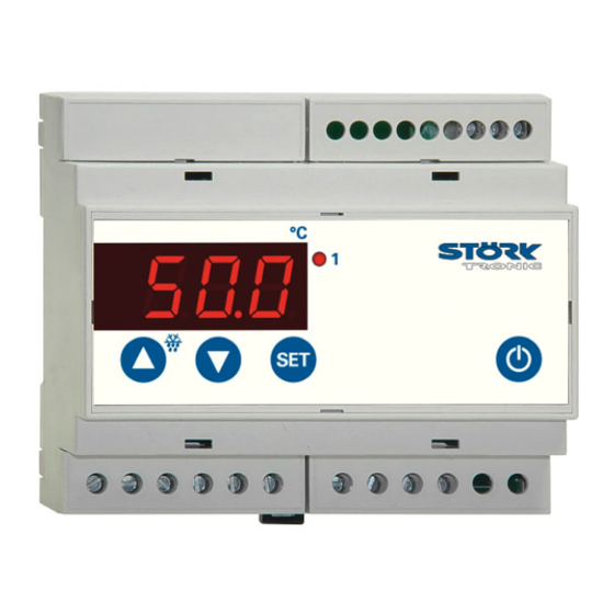
ST129-JA1TA.10
Temperature controller
Order number 900321.003
Wiring diagram
Product description
The controller ST129-JA1TA.10 is intended for the assembly on DIN rail, which allows easy in-
stallation in the switch gear cabinet. It was specifically developed for direct switching at high per-
formances. Given the high maximum electric load of 16A (ohm) and 6A (inductive) it can operate
without cut-out relay in many cases. The controller is supplied with 230V AC and has 4 keys.
Sensor: Pt100, PTC
Range: dependent on the type of sensor
Housing size(L x W x H): 106 x 95 x 60mm
Installation: Clip-on mounting on DIN-Rail 35 x 7.5mm
Connector: screw terminal
Advertisement

Subscribe to Our Youtube Channel
Related Manuals for STORK TRONIC ST129-JA1TA.10


Summary of Contents for STORK TRONIC ST129-JA1TA.10
- Page 1 Wiring diagram Product description The controller ST129-JA1TA.10 is intended for the assembly on DIN rail, which allows easy in- stallation in the switch gear cabinet. It was specifically developed for direct switching at high per- formances. Given the high maximum electric load of 16A (ohm) and 6A (inductive) it can operate without cut-out relay in many cases.
- Page 3 SOFTWARE .10 Adjustment options Key 1: UP Pressing this key you can increase the parameter or parameter value or scroll the parameter list. Key 2: DOWN Pressing this key you can decrease the parameter or parameter value or scroll the parameter list.
- Page 4 Second control level (P parameters): Setting of control parameters Simultaneously pressing the UP and DOWN key for at least 4 seconds opens a parameter list containing control parameters. With the UP and DOWN keys the list can be scrolled in both directions. Pressing the SET key will give you the value of the respective parameter.
- Page 5 Parameter description: P2: Hysteresis contact K1 The hysteresis can be set symmetrically or one-sided at the setpoint (see A40, A41). At one-sided setting, the hysteresis works downward with heating contact and upward with cooling contact. At symmetrical hysteresis, half of the hysteresis’ value is effective below and half of the value above the switching point (see fig.
- Page 6 d2: Defrosting temperature limit This permits to terminate defrosting when the adjusted desired temperature value is reached. The defrosting time set with "d3" nevertheless runs at the same time, i.e. it functions as safety net to terminate the defrosting process in case the defrosting temperature is not reached. d3: Defrosting time limit After the here set time the defrosting process is terminated.
- Page 7 Third control level, (A parameters): Setting of control parameters Access to the third control level is granted when selecting the last P-parameter on the second control level. Continue to press the UP key for approximately 10 seconds until “PA” appears. Continue to press the UP key and additionally press the DOWN key for about 4 seconds and the first A-parameter of the third control level is indicated.
- Page 8 Para- Function description Adjustment range Standard Custom meter setting setting Minimum action time 0…600 sec. 0 sec. contact K1 ”On” Minimum action time 0…600 sec. 0 sec. contact K1 ”Off” Delay after “Power-on” 0…600 sec. 0 sec. Alarm suppression after 0…60 min.
- Page 9 Parameter description: The following values can change the equipment characteristics and are therefore to be set with utmost care. A1: Switch mode contact K1 The switch mode for the relay, i.e. cooling or heating function, can be programmed independently at works. Heating function means that the contact opens as soon as the setpoint is reached, thus power interruption.
- Page 10 A50: Minimum action time contact K1 ”On” A51: Minimum action time contact K1 ”Off” These parameters permit a delay in switching on/off the relay in order to reduce the switching frequency. The adjusted time sets the entire minimum time period for a switching-on or switching- off phase.
- Page 11 Status messages Message Cause Error elimination “AUS” or “OFF” Standby modus, no regulation Switch on with standby key Sensor error, Check sensor short-circuit at sensor F1 Sensor error, Check sensor open-circuit at sensor F1 _ _ _ Key-lock active Change parameter P19 or A19 display flashes Temperature alarm at too high or too low temperature (if activated) see A31...
- Page 12 Technical data of ST129-JA1TA.10 Measuring input Resistance sensor PTC, Pt100 or Pt1000, 2-wire connection Measuring range: Pt100 -80° C...+400 ° C Pt1000 -99° C...+350° C -50° C...+150 ° C Measuring accuracy of the controller at 25°C: +/-0.5K und +/-0.5% of measuring range...
Need help?
Do you have a question about the ST129-JA1TA.10 and is the answer not in the manual?
Questions and answers