Table of Contents
Advertisement
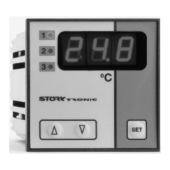
ST72-31.03
Temperature controller
Order number 900165.047
Wiring diagram
Product description
The switching exits of the thermal controller can be programmed as
-two-point controller with alarm contact
-three-point controller with alarm contact
-two-stage controller with alarm contact
-three-stage controller.
The setpoint and all parameters of the controller are set on a three-field plastic foil keyboard.
Range: dependent on type of sensor
Front size: 72mm x 72mm
Panel cut-out: 66.5mm x 66.5mm
Connector: plug and socket
Power supply: 230V
Advertisement
Table of Contents

Subscribe to Our Youtube Channel
Related Manuals for STORK TRONIC ST72-31.03


Summary of Contents for STORK TRONIC ST72-31.03
- Page 1 ST72-31.03 Temperature controller Order number 900165.047 Wiring diagram Product description The switching exits of the thermal controller can be programmed as -two-point controller with alarm contact -three-point controller with alarm contact -two-stage controller with alarm contact -three-stage controller. The setpoint and all parameters of the controller are set on a three-field plastic foil keyboard.
- Page 3 Software .03 Adjustment options Key UP Pressing this key you can increase the parameter or parameter value or scroll the parameter list. Key DOWN Pressing this key you can decrease the parameter or parameter value or scroll the parameter list. At alarm the buzzer function can be switched off with this key. Key 4: SET While SET key is pressed, the setpoint is indicated.
- Page 4 Second control level (P parameters): Setting of control parameters Simultaneously pressing the UP and DOWN key for at least 4 seconds opens a parameter list containing control parameters. With the UP and DOWN keys the list can be scrolled in both directions. Pressing the SET key will give you the value of the respective parameter.
- Page 5 Parameter description: P1: Setpoint / DeltaW for control circuit 2 Adjusting the setpoint of control circuit 2. If A5=1, the setpoints for control circuit 1 and 2 are linked with one another via switching difference DeltaW, which can be adjusted with P1. (operation with DeltaW) The following applies: setpoint thermostat 2 = setpoint control circuit 1 + delta W2.
- Page 6 Boundary alarm function (see fig. 5): Range alarm function (see fig. 6): The alarm contact is closed if the process Opposite switching behaviour to the boundary temperature is above the upper or below the lower value alarm. The alarm contact is closed if the boundary value.
- Page 7 Para- Function description Adjustment range Standard Custom meter setting setting Function alarm exit 0: Boundary alarm, relative 1: Boundary alarm, absolute 2: Range alarm, relative 3: Range alarm, absolute 0: no special function Special function at boundary 1: flashing display or range alarm Setpoint display 0: display shows actual value...
- Page 8 Parameter description: The following values can change the equipment characteristics and are therefore to be set with utmost care. A1: Switch mode contact K1 A2: Switch mode contact K2 The switch mode for the relays, i.e. cooling or heating function, can be programmed independently at works. Heating function means that the contact opens as soon as the setpoint is reached, thus power interruption.
- Page 9 A40: Hysteresis mode contact K1 A41: Hysteresis mode contact K2 These parameters allow selection as to whether the hysteresis values which are adjustable with P32, are set symmetrically or one-sided at the respective switching point. At symmetrical hysteresis, half of the hysteresis’ value is effective below and half of the value above the switching point.
- Page 10 Technical data of ST72-31.03 Input external potential-free contact Measuring input F1: Temperature sensor, available types: Pt100, 2-wire or 3-wire Thermo element, type J or type K Linear input 0-10V or 0-20mA Measuring ranges: Pt100: -200°C...+840 °C PTC: -50...145°C Type J: -200...1200°C...
- Page 11 Selection of sensor type Pt100, 2-wire (standard setting) Connection: clamp 11 and 13 Connection Dip switch 4,5 and 6 in position ON Pt100, 3-wire Connection: clamp 11, 12(correction) and 13 Connection Dip switch 4 in position ON Thermo element type J (Fe-CuNi) Connection: clamp 12 (+) and 13 (-) Connection Dip switch 2 in position ON...
Need help?
Do you have a question about the ST72-31.03 and is the answer not in the manual?
Questions and answers