Dahua VTH5221 Series User Manual
Digital vth
Hide thumbs
Also See for VTH5221 Series:
- User manual (109 pages) ,
- Quick start manual (28 pages) ,
- User manual (93 pages)
Table of Contents
Advertisement
Advertisement
Table of Contents

Related Manuals for Dahua VTH5221 Series


Summary of Contents for Dahua VTH5221 Series
- Page 1 Digital VTH User’s Manual V1.2.0...
-
Page 2: Foreword
UI operation and technical parameter of digital VTH products matched with version 4.2 UI interface. Models Type Model Series Specific Model VTH5221DW, VTH5221D, VTH5221DW-C, VTH5221D-C, VTH5221 series VTH5221E-H, VTH5221EW-H VTH5241 series VTH5241DW Type A VTH1520A, VTH1520AS-H, VTH1520AH, VTH1520AS Digital... - Page 3 Version Revision Content Release Date and installation drawing. About the Manual The manual is for reference only. If there is inconsistency between the manual and the actual product, the actual product shall prevail. We are not liable for any loss caused by the operations that do not comply with the manual. ...
-
Page 4: Important Safeguards And Warnings
Important Safeguards and Warnings The following description is the correct application method of the device. Please read the manual carefully before use, in order to prevent danger and property loss. Strictly conform to the manual during application and keep it properly after reading. Operating Requirement Please don’t place and install the device in an area exposed to direct sunlight or near heat ... -
Page 5: Table Of Contents
Product Profile ..........................1 Function ............................1 2 Product Structure ..........................2 Front Panel ............................ 2 2.1.1 VTH5221 Series /VTH5241 Series ..................2 2.1.2 VTH5221E-H/VTH5221EW-H .................... 3 2.1.3 VTH15 Series Type A/B ...................... 4 2.1.4 VTH15 Series Type CH /VTH5222CH ................6 2.1.5 VTH1660CH ........................ - Page 6 6.2.1 Ring Settings ........................38 6.2.2 DND Settings ........................42 6.2.3 Alarm Setting ........................43 6.2.4 Mode Setting ........................47 6.2.5 Forward Setting ........................ 48 6.2.6 General Setting ......................... 49 6.2.7 Product Info ........................55 Project Settings ........................... 56 6.3.1 Forget Password ....................... 56 6.3.2 Network Settings .......................
-
Page 7: Product Overview
Product Overview Product Profile VTH series product is a digital video intercom home station for numerous homes, integrating monitoring, intercom and unlocking. With embedded technology, all IP network, SNMP (Simple Network Management Protocol) technology and network encryption technology, achieve more stable system operation, richer functional extension, more convenient system management and safer data transmission. -
Page 8: Product Structure
Product Structure Front Panel 2.1.1 VTH5221 Series /VTH5241 Series VTH5221D is a 7″ digital indoor monitor. Their front panels have the same size, as shown in Figure 2-1. Please refer to Table 2-1 for details. Figure 2-1 Name Description Camera occlusion Slide it to occlude or open the camera. -
Page 9: Vth5221E-H/Vth5221Ew-H
Name Description VTO and fence station. During speaking, press this key to exit speaking. Press this key to call the Call Center in case of emergency. Table 2-1 2.1.2 VTH5221E-H/VTH5221EW-H VTH5221E-H/VTH5221EW-H is two types of digital VTH with handset. They are the same except appearance color, as shown in Figure 2-2 and Figure 2-3. -
Page 10: Vth15 Series Type A/B
Name Description TF card slot TF card slot, max. 64GB. RJ45 port RJ45 network cable port. RJ11 port Port of connecting cable between handset and VTH. Table 2-3 2.1.3 VTH15 Series Type A/B In VTH15 series, different types of devices have different front panels. Figure 2-4 VTH15 Series Type A Icon Name... - Page 11 Icon Name Description If this indicator turns on, it represents normal Network communication with VTO. indicator If this indicator turns off, it represents abnormal communication with VTO. Message If this indicator turns on, it represents that there are indicator unread messages.
-
Page 12: Vth15 Series Type Ch /Vth5222Ch
Icon Name Description Press this key during calling, talking, monitoring and Unlock speaking of VTO, so corresponding VTO will be unlocked. Message If this indicator turns on, it represents that there are indicator unread messages. Power If this indicator turns on in green, it represents normal indicator power supply. -
Page 13: Vth1660Ch
Icon Name Description Press this key to call the Call Center in case of emergency. Menu Press this key to return to main menu. In case of incoming call, press this key to answer the call. During talk, press this key to hang up. Call ... -
Page 14: Vth2221A
Rear Panel Port 2.2.1 VTH5221 Series /VTH5241 Series Port positions are slightly different on the rear panel of VTH5221 series and VTH5241 series, but the same port owns the same function. Taking VTH5221 as an example, specific functions of ports are introduced, as shown in Figure 2-9. -
Page 15: Vth5221E-H/Vth5221Ew-H
Figure 2-9 2.2.2 VTH5221E-H/VTH5221EW-H Port positions are slightly different on the rear panel, but the same port owns the same function. VTH5221E-H/VTH5221EW-H front panels are shown in Figure 2-10. Figure 2-10 2.2.3 VTH15 Series Type A/Type B/Type CH In VTH15 series, different types of digital VTH have different port positions, but the same port provides the same function. -
Page 16: Vth5222Ch/Vth5222Chw-2
In VTH15 type A/type B series, different types of digital VTH have different port positions, but the same port provides the same function. Taking VTH1560B as an example, specific functions of ports are introduced, as shown in Figure 2-12. Figure 2-12 2.2.4 VTH5222CH/VTH5222CHW-2 Except different numbers of 2-wire port, VTH5222CH and VTH5222CHW-2 are the same in other aspects. -
Page 17: Vth2221A
Figure 2-15 2.2.6 VTH2221A VTH2221A provides 8-ch alarm input ports, 1-ch network port and power port, as shown in Figure 2-14. Figure 2-14 Product Structure 11... -
Page 18: Network Diagram
Network Diagram 2-wire System Network diagram of 2-wire system is shown in Figure 3-1. Figure 3-1 Digital System Digital system network consist of two types: VTH adopts PoE power supply from floor switch, as shown in Figure 3-2. Network Diagram 12... - Page 19 Figure 3-2 VTH adopts independent power supply from power supply device, as shown in Figure 3-3. Network Diagram 13...
- Page 20 Figure 3-3 Network Diagram 14...
-
Page 21: Device Installation
Device Installation Installation Flow Chart VTH installation flow chart is shown in Figure 4-1 Please install VTH in the following steps. Figure 4-1 For cable connection, please refer to “2.2 Rear Panel Port“. For device installation, please refer to “4.4 Device Installation“. ... -
Page 22: Installation Requirement
Sequence Item Content Inspect whether it is torn or damaged. Don’t tear or discard the label, otherwise warranty Label on the service won’t be provided. When dialing our device after-sales hotline, please provide serial number of the product. Device Appearance Inspect whether there are obvious damages. -
Page 23: Installation With 86 Box
Figure 4-2 4.4.2 Installation with 86 Box Install the device with 86 box, which is suitable for all types of devices. Take “VTH1560B/BW “ for example. Step 1 Embed 86 box into a wall at a proper height. Step 2 Fix installation bracket onto 86 box with screws. - Page 24 Step 2 Please connect wire by reference to Figure 2-10. Step 3 After wiring, guide the wire through wire outlet in the rear or at the bottom of desktop bracket. Step 4 Put the handset VTH along slot at the top of metal bracket, and install it into the bracket.
-
Page 25: Device Debugging
Device Debugging Carry out debugging to ensure that the device can realize basic network access, call and monitoring functions after installation. Before debugging, please check whether the following work has been completed. Check whether there is short circuit or open circuit. Power on the device only after the ... - Page 26 Figure 5-1 Enter “Password” and “Confirm Password”, and click “Next”. Step 3 The system displays “step two”, as shown in Figure 5-2. This password is used to login WEB interface. It shall be at least 8 characters, and shall include at least two types of number, letter and symbol. Figure 5-2 Select “Email”...
- Page 27 Figure 5-3 Click “OK”. Step 6 The system displays WEB login interface, as shown in Figure 5-4. Figure 5-4 Enter user name and password, and click “Login”. Step 7 Log in the WEB interface of the device. Default user name is admin. Password is the one set during initialization.
- Page 28 Figure 5-5 Enter the planned “IP Address”, “Subnet Mask” and “Default Gateway”, and click “OK”. Step 2 After modification is completed, VTO reboots automatically, while the following two cases occur at WEB interface. If PC is in the planned network segment, WEB interface jumps to new IP login ...
- Page 29 Figure 5-7 Step 2 Select server type. When this VTO or another VTO works as SIP server, select “Server Type” to be “VTO”. It applies to a scenario where there is only one unit. When the platform (such as Express/DSS) works as SIP server, select “Server ...
- Page 30 Set parameters by reference to Table 5-1 and click “OK”. The VTO reboots automatically, and web interface jumps to login interface. Parameter Description IP Address IP address of VTO, which works as SIP server. Port It is 5060 by default. Username Use default value.
- Page 31 Figure 5-9 Click “Add”. Step 3 The system displays “Add” interface, as shown in Figure 5-10. Figure 5-10 Step 4 Set VTO parameters by reference to Table 5-3. Parameter Description Rec No. VTO number. Register Password Signaling interactive use in SIP system. Adopt default value. IP Address IP address of VTO.
- Page 32 The system displays “Room No. Management” interface, as shown in Figure 5-11. Figure 5-11 Click “Add”. Step 2 The system displays “Add” interface, as shown in Figure 5-12. Figure 5-12 Step 3 Set VTH parameters by reference to Table 5-4. Device Debugging 26...
-
Page 33: Vth Settings
Parameter Description First Name Last Name Set VTH username and nickname, in order to distinguish. Nick Name Set VTH room number. VTH short number consists of 1~6 numbers, which may include number and “#”. It shall be consistent with room number configured at VTH. - Page 34 Figure 5-13 Enter “Password”, “Confirm Pwd” and “Email”. Step 2 Step 3 Press [OK]. The system displays main interface, as shown in Figure 5-14. Figure 5-14 5.1.2.2 Set Device Network According to available network connection modes, configure VTH network information. IP addresses of VTH and VTO shall be in the same network segment.
- Page 35 The system displays “Network” interface, as shown in Figure 5-15 or Figure 5-16. Only devices with the wireless function can access to wireless network. Figure 5-15 Figure 5-16 Step 4 Set according to actual network access mode. Enter “Local IP”, “Subnet Mask” and “Gateway”, press [OK]. Or press to enable DHCP function and obtain IP info automatically.
- Page 36 Figure 5-17 Connect Wi-Fi. The system has 2 access ways as follows. At “WLAN” interface, select Wi-Fi, click “Wireless IP” tab to enter “Local IP”, ◇ “Subnet Mask” and “Gateway”, and press [OK]. At “WLAN” interface, select Wi-Fi, click “Wireless IP” tab, press ◇...
- Page 37 The system displays “VTH Config” interface, as shown in Figure 5-19. Figure 5-19 Step 4 Set VTH info. Be used as a master VTH. Enter “Room No.” (such as 9901 or 101#0) and press “OK” to save. “Room no.” shall be the same with “VTH Short No.”, which is set when adding ...
- Page 38 Figure 5-20 Step 4 Set parameters of SIP server by reference to Parameter Description When the platform works as SIP server, server IP is IP address of the platform. Server IP When VTO works as SIP server, server IP is IP address of the VTO.
- Page 39 Parameter Description When the platform works as SIP server, server IP is IP address of the platform. Server IP When VTO works as SIP server, server IP is IP address of the VTO. When the platform works as SIP server, network port is 5080. Network Port When VTO works as SIP server, network port is 5060.
-
Page 40: Debugging Verification
Switch the “Enable Status” to be “User Name” and “Password” shall be consistent with WEB login user name and password of VTO. Otherwise, it will fail to connect. Add sub VTO or fence station. Enter “Sub VTO/Fence Station Name”, “Sub VTO/Fence Station IP address”, “User Name”... - Page 41 Select “Monitor > Door”, as shown in Figure 5-23. Select the VTO to enter monitoring image, as shown in Figure 5-24. The following figure means that SD card has been inserted into VTH. If SD card is not inserted, recording and snapshot icons are gray. Figure 5-23 Figure 5-24 Device Debugging 35...
-
Page 42: Interface Operation
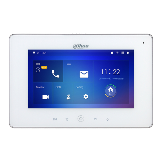
Interface Operation Main Interface There are six items at the main interface, namely, call, info, monitor, SOS, setting and arm/disarm, as shown in Figure 6-1. For description of every item, please refer to Table 6-1. Name Description Room No. Number of the room where VTH is located. Call a user. - Page 43 Name Description Press [Setting], input login password and enter system setting interface. Setting Press [Setting] for over 6 seconds, input the password set during initialization, and enter project setting interface. Press this icon to call Management Center. Monitor Monitor the VTO, fence station, IPC, NVT, HCVR and XVR. Table 6-1 Table 6-2 Figure 6-1 Name...
-
Page 44: Setting
Name Description : Wired network connection icon, meaning that the device isn’t connected with network. : Wired network connection icon, meaning that the device has connected with network in a wired way. : Wi-Fi network connection icon, meaning that the device ... - Page 45 You can only customize 10 ring tones. Other ring tones will not be displayed at the VTH. 6.2.1.1 VTO Ring Set a ring for the connected VTO, and support to set maximum 20 VTOs. Step 1 Press [Setting]. The system pops up “Password” prompt box. Step 2 Input login password and press [OK].
- Page 46 Select “Ring > VTH Ring Setup”. Step 3 The system displays “VTH Ring Setup” interface, as shown in Figure 6-3. Figure 6-3 Step 4 Press text box to select rings, and press to set the volume. 6.2.1.3 Alarm Ring Set the ring when VTH gives an alarm. Step 1 Press [Setting].
- Page 47 Figure 6-4 Step 4 Press text box to select rings, and press to set the volume. 6.2.1.4 Other Set VTO ring time, VTH ring time, MIC volume, talk volume and ring mute setting. “VTO Ring Time” and “VTH Ring Time” of extension VTH are synchronized with master VTH, and cannot be set.
-
Page 48: Dnd Settings
Figure 6-5 to enable “Ring Step 4 Press to set the time or volume. Press Mute”, and the icon becomes VTO ring time: ring time when VTO calls VTH. VTH ring time: ring time when another VTH calls this VTH. 6.2.2 DND Settings Set to avoid incoming calls within a time period. -
Page 49: Alarm Setting
Figure 6-6 Step 4 Press to enable DND function, and the icon becomes The system displays DND period, as shown in Figure 6-7. Figure 6-7 Step 5 Press time text box; set start time and end time. Step 6 Press [Click to select week] and select DND week. Step 7 Press [OK] to save settings. - Page 50 Zones can be set under disarm mode. 6.2.3.1 Wire Zone Set zone type, NO/NC, alarm status and delay. It supports to set 8 zones at most. Step 1 Press [Setting]. The system pops up “Password” prompt box. Step 2 Input login password and press [OK]. Default login password is 123456.
- Page 51 Parameter Description It includes instant alarm, delay alarm, bypass and remove. Instant alarm: in case of alarm after arm, produce alarm sound at once and enters alarm status. Delay alarm: in case of alarm after arm, enter alarm status after some time. ...
- Page 52 Figure 6-9 Step 4 Press [Add]. Step 5 Press wireless code button of wireless device. Please refer to wireless device user’s manual for details. After successful coding, display area info. Step 6 Press corresponding positions to set alarm status, enter delay and exit delay. Please refer to Table 6-3 for details.
-
Page 53: Mode Setting
Figure 6-10 Step 4 Press to enable alarm output function, and the icon becomes 6.2.4 Mode Setting Set area on/off status under different modes. Area mode can be set only in disarm status. Step 1 Press [Setting]. The system pops up “Password” prompt box. Step 2 Input login password and press [OK]. -
Page 54: Forward Setting
Figure 6-11 Step 4 Select arm mode in every tab. Step 5 Press in every area to add it into arm mode. Multiple areas can be added into one arm mode simultaneously, whereas one area can be added into different modes. 6.2.5 Forward Setting Forward incoming calls. -
Page 55: General Setting
Figure 6-12 Step 4 Input VTH no. in the corresponding forward mode, press to enable the forward function. Please refer to Table 6-4 for details. Parameter Description Always All incoming calls will be forwarded to preset number immediately. When the user is busy, incoming call from the third party will be forwarded to preset number. - Page 56 Parameters at this interface are set on master VTH only, and extension VTH synchronizes with master VTH. Step 1 Press [Setting]. The system pops up “Password” prompt box. Step 2 Input login password and press [OK]. Default login password is 123456. Please refer to “6.2.6.3 Password Setting“ for details.
- Page 57 Figure 6-14 DST setting Press of system time and the icon becomes , so as to enable manual setting function. Press to enable DST. Press DST text box, and select DST start time and end time. 6.2.6.2 Display Setting Set VTH screen brightness, screensaver time and clean.
- Page 58 Figure 6-15 Step 4 Set parameters. ; set “Brightness” and “Screensaver Time”. Press Press [Clean] and the screen will be locked for 10 seconds. During the period, clean the screen. It restores after 10 seconds. 6.2.6.3 Password Setting Set login password, arm/disarm password, unlock password and anti-hijacking password of VTH setting interface.
- Page 59 Figure 6-16 Enter “New Password” and “Confirm Password”. Step 4 Step 5 Press [OK] to complete password modification. 6.2.6.4 Other Settings Set monitor time, record time, VTO message time, VTO talk time, resident-to-resident call enable, resident-to-resident call time, auto capture and touch ring. Extension VTH can set “Auto Capture”...
- Page 60 Figure 6-17 Step 4 Set parameters. Please refer to Table 6-5 for details. Parameter Description Operation Maximum time to monitor VTO, IPC, fence station, Monitor Time HCVR, NVR and DVR. Maximum recording time of videos during call, talk, Record Time monitoring and speaking.
-
Page 61: Product Info
Parameter Description Operation After auto capture is enabled, 3 pictures will be captured automatically when VTO calls VTH. View them at “Info > Record and Picture” interface. Auto Capture This function is valid only when SD card is inserted. After enabling touch ring, there will be a ring when Touch Ring touching the screen. -
Page 62: Project Settings
Project Settings 6.3.1 Forget Password If you forget initialization password when entering project settings interface, reset password through “Forget Password” at the interface or in VDPconfig tool. 6.3.1.1 Reset the Password at the Interface Step 1 Press [Setting] for over 6 seconds. The system pops up “Password”... -
Page 63: Network Settings
6.3.2 Network Settings Set VTH network info according to actual conditions, since different types of devices support different access modes. IP addresses of VTH and VTO shall be in the same network segment. Otherwise, VTH will fail to obtain VTO info after configuration. Step 1 Press [Setting] for over 6 seconds. - Page 64 Figure 6-20 Figure 6-21 Step 4 Set according to actual network access mode. Enter “Local IP”, “Subnet Mask” and “Gateway” manually, press [OK]. Or press to enable DHCP function and obtain IP info automatically. If the device has wireless function, please click “LAN” tab to set it. ...
-
Page 65: Vth Config
Figure 6-22 Connect Wi-Fi. The system has 2 access ways as follows. At “WLAN” interface, select Wi-Fi, click “Wireless IP” tab to enter “Local IP”, ◇ “Subnet Mask” and “Gateway”, and press [OK]. At “WLAN” interface, select Wi-Fi, click “Wireless IP” tab, press ◇... -
Page 66: Vto Config
Figure 6-24 Step 4 Set VTH info. Be used as a master VTH. Enter “Room No.” (such as 9901 or 101#0). “Room no.” shall be the same with “VTH Short No.”, which is set when adding VTH at WEB interface. Otherwise, it will fail to connect VTO. In case of extension VTH, room no. -
Page 67: Default
Figure 6-25 Step 4 Add VTO or fence station. Add main VTO. Enter main VTO name, VTO IP, “User Name” and “Password”. Switch the “Enable Status” to be “User Name” and “Password” shall be consistent with WEB login user name and password of VTO. -
Page 68: Reset Msg
6.3.6 Reset MSG Modify the bonded Email. Step 1 Press [Setting] for over 6 seconds. The system pops up “Password” prompt box. Step 2 Enter the password set during initialization, and press [OK]. Step 3 Press [Reset MSG]. The system displays “Reset MSG” interface, as shown in Figure 6-26. Figure 6-26 Enter “New Email”... - Page 69 Figure 6-27 6.4.1.1 Add User Step 1 Press [Add]. The system displays “User Info” interface, as shown in Figure 6-28. Figure 6-28 Enter “Last Name”, “First Name” and “Room No.” of contact person. Step 2 Step 3 Press [OK] to complete adding. Interface Operation 63...
-
Page 70: Call User
6.4.1.2 Edit Contact Info Select the contact person, press to edit the info. 6.4.1.3 Delete Contact Person Press [Edit], select the contact person and press [Delete] to delete the contact person. Multiple contact persons can be selected once. 6.4.2 Call User Make sure that resident-to-resident call function has been enabled. - Page 71 Call a user in other buildings or units, add the building number. For example, dial 1#1#101 to call Building 1 Unit 1 Room 101. If master VTH (101#0) calls extension (101#1), please enter room no.: #1; if the extension calls master VTH, please enter room no.: #0. Step 3 Press to start.
-
Page 72: Call From User
Figure 6-30 Figure 6-31 6.4.2.2 Call User in Contact Please add contact persons to the contact, by reference to “6.4.1.1 Add User“. Select “Call > Contact”. Step 1 Step 2 Select the one you want to call. Step 3 Press to start. -
Page 73: Call From Vto
Figure 6-32 Press to talk with each other, as shown in Figure 6-33. For key description, please refer to Table 6-6. Press to hang up. Figure 6-33 6.4.4 Call from VTO Step 1 Dial VTH room no. (such as 9901) at VTO, to call VTH. VTH pops up a waiting picture, as shown in Figure 6-34. - Page 74 Answer the call and talk with each other. For key description, please refer to Table 6-6. Figure 6-34 Description Press this key to unlock the VTO remotely. The system provides 2-channel unlock function. If the icon is gray, it means that unlock function of this channel is not available. This key means to talk with the opposite end device.
-
Page 75: Recent Call
Description Press this key to refuse. Table 6-6 6.4.5 Recent Call View and manage the missed call, accepted call and called log of this VTH. Meanwhile, call back the contact persons. Select “Call > Recent Call”, and the system displays “Recent Call” interface. -
Page 76: Monitor
Monitor VTH is able to monitor VTO, fence station or IPC. 6.5.1 Monitoring of VTO Please confirm user name and password in VTH, which are set when adding VTO. They shall be consistent with WEB login user name and password of VTO. Otherwise, it will fail to obtain videos during monitoring. - Page 77 Icon Description Press this key to snapshot. This key is gray if SD card is not installed. Press this key to record. Complete recording when the call is completed or by pressing Videos are stored in SD card of this VTH. If SD card is full, the earlier videos will be covered.
-
Page 78: Monitoring Of Ipc
Icon Description Press this key to unlock VTO remotely. The system provides 2-channel unlock function. If the icon is gray, it means that unlock function of this channel is not available. Press this key to snapshot. This key is gray if SD card is not installed. Press this key to record. - Page 79 Figure 6-38 Step 2 Press [Add]. The system displays “Add IPC” interface, as shown in Figure 6-39. Figure 6-39 Step 3 Please refer to Table 6-9 to configure camera parameters. Parameter Description Press this key to select IPC, NVR, DVR and HCVR. Select IPC, meaning that VTH obtains video stream from the connected ...
- Page 80 Parameter Description IPC32 Name Input IPC/NVR/DVR/HCVR name. Input IP address of the connected IPC/NVR/DVR/HCVR. User Name Input user name password login interface IPC/NVR/DVR/HCVR. Password Port Default port is 554. Select stream type according to needs, including main stream and extra stream.
-
Page 81: Favorite
Step 2 Select IPC to be monitored, and press The system displays monitoring interface, as shown in Figure 6-40. Figure 6-40 Step 3 Please monitor the VTO by reference to Table 6-8. 6.5.3 Favorite Display VTO, fence stations or IPC that have been added to favorites. To view favorite list, please ensure that VTO, fence station or IPC have been added to favorites. -
Page 82: Sos
Figure 6-41 Step 2 Select the device to be monitored, and press The system displays monitoring interface. In case of multiple devices in “Favorite” tab, press to switch and monitor them. Please ensure that management center has been connected. Otherwise, it will fail to call. In emergency, press button on the front panel, or press [SOS] at the main interface to call management center. -
Page 83: Guest Message
Figure 6-42 Alternatively, select “Info > Security Alarm”, and the system displays “Security Alarm” interface, as shown in Figure 6-43. “All” tab displays all alarm info of the system, whereas “Unread” tab displays unread alarm info. Press [Edit] to select the info; press [Delete] to delete the selected info. ... -
Page 84: Publish Info
in SD card. If SD card is not inserted, but VTO WEB has set FTP and selected “Video-audio Message Uploading”, this function is valid too. All messages will be uploaded to FTP. Select “Info > Guest Message”, and the system displays “Guest Message” interface, as shown in Figure 6-44. -
Page 85: Video Pictures
Figure 6-45 6.7.4 Video Pictures When a SD card is inserted into the device, this function is valid. All videos and pictures are stored in SD card. Select “Info > Video Pictures”, and the system displays “Video Pictures” interface, as shown in Figure 6-46. -
Page 86: Unlock Function
Figure 6-46 Unlock Function When the VTH is being called, during monitoring, talking and speaking, press unlock button, and the VTO will be unlocked remotely. Arm and Disarm Function 6.9.1 Arm In case of triggering alarm after arm, produce linkage alarm and upload alarm info. Please ensure that the area has been added into arm mode. -
Page 87: Disarm
Figure 6-47 Step 2 Select arm mode. The system displays password input interface. Step 3 Enter arm and disarm password; press [OK]. The device beeps continuously, which represents successful arm. The key displays corresponding arm mode. Default password of arm and disarm is 123456. Please refer to “6.2.6.3 Password ... -
Page 88: Dss Mobile For Vdp
DSS Mobile for VDP You can download the DSS mobile app and bind your VTH to the app to unlock the door, talk to the connected VTO devices, call the management center, and view call records and messages. Downloading the App Before start, make sure your VTO, VTH, and DSS server are properly connected. - Page 89 Figure 7-3 , and then scan the Register code on the VTH. See “Step 2“ in “7.1 Step 2 Downloading the App“. The IP address and port number of your DSS server is displayed. DSS Mobile for VDP 83...
- Page 90 Figure 7-4 Step 3 Tap Confirm, then Input the user name and password you need, and then tap Registration. You can register 5 users on a VTH at most. DSS Mobile for VDP 84...
- Page 91 Figure 7-5 Step 4 Tap Login. The Login interface is displayed. Step 5 Input the user name and password you registered, and then tap Login. The Call Records interface is displayed. DSS Mobile for VDP 85...
- Page 92 Figure 7-6 DSS Mobile for VDP 86...
-
Page 93: Call Functions
Call Functions 7.3.1 Configuring Call Forward Confirm your SIP ID, and then configure call forward on the VTH. If any device is calling the VTH, you will receive the call on the phone. Step 1 Log in the app, and then tap Setting. The Settings interface is displayed, and the SIP ID here is 3#1#1001#115. - Page 94 Figure 7-8 Step 3 Input the password you configured, and then tap Forward. The Forward interface is displayed. Figure 7-9 You can select the forward type you need: Always: All the calls come to this VTH will be forwarded. Busy: If the VTH is busy, then the call will be forwarded.
-
Page 95: Calling Operations
7.3.2 Calling Operations After call forward is properly configured, you can receive and answer phone calls from the VTO or the management center. When the VTO is making video call, you can answer the call and unlock the door remotely. Figure 7-10 You can also receive the call from the management center. - Page 96 Figure 7-11 DSS Mobile for VDP 90...
-
Page 97: Monitor
Monitor You can add the connected VTO manually to do monitor, voice communication, and unlock. Step 1 Log in the app, and then tap Monitor. The Monitor interface is displayed. Figure 7-12 You can tap Call Manager to call the management center. Tap the “+”... - Page 98 Figure 7-13 Tap Open Door to unlock the door. Tap Speaking to do voice communication with the VTO. DSS Mobile for VDP 92...
-
Page 99: Call Records
Call Records After call forward is properly configured (See “7.3.1 Configuring Call Forward“), you can view the call records from the VTO or the management center. Step 1 Log in the app, and then Tap Call Records. The Call Records interface is displayed. Figure 7-14 Step 2 You can view the missed calls and all the records. -
Page 100: Message
Message Step 1 Log in the app, and then tap Message. The Message interface is displayed. You can view the access messages and alarm messages. Figure 7-14 DSS Mobile for VDP 94... - Page 101 Figure 7-15 You need to enable event subscription first. See “7.7 Setting.” DSS Mobile for VDP 95...
-
Page 102: Setting
Setting Step 1 Log in the app, and then tap Setting. The Settings interface is displayed. Figure 7-16 Step 2 to enable the function you need, and then it changes to Enable Event Subscription, and then you can view the access messages and alarm messages. -
Page 103: Appendix 1 Cybersecurity Recommendations
Appendix 1 Cybersecurity Recommendations Cybersecurity is more than just a buzzword: it’s something that pertains to every device that is connected to the internet. IP video surveillance is not immune to cyber risks, but taking basic steps toward protecting and strengthening networks and networked appliances will make them less susceptible to attacks. - Page 104 We suggest you to change default HTTP and other service ports into any set of numbers between 1024~65535, reducing the risk of outsiders being able to guess which ports you are using. Enable HTTPS We suggest you to enable HTTPS, so that you visit Web service through a secure communication channel.
- Page 105 use VLAN, network GAP and other technologies to partition the network, so as to achieve the network isolation effect. Establish the 802.1x access authentication system to reduce the risk of unauthorized access to private networks. Cybersecurity Recommendations 99...
Need help?
Do you have a question about the VTH5221 Series and is the answer not in the manual?
Questions and answers