ETC Element User Manual
Hide thumbs
Also See for Element:
- User manual (306 pages) ,
- User manual (282 pages) ,
- How to open (2 pages)

Related Manuals for ETC Element


Summary of Contents for ETC Element
- Page 1 Element User Manual Version 2.9.0 Part Number: 4330M1210-2.9.0 Rev: A Released: 2019-08...
- Page 2 To view a list of ETC trademarks and patents, go to etcconnect.com/ip. All other trademarks, both marked and not marked, are the property of their respective owners. ETC intends this document, whether printed or electronic, to be provided in its entirety.
-
Page 3: Table Of Contents
Table of Contents Introduction Using this Manual Register Your Console Online Eos Family User Forums Help from ETC Technical Services Other Reference Materials Important Concepts Console Overview Element Geography Console Components Cleaning Your Console Element Console Capacities System Basics About System Basics... - Page 4 Exporting Logs Deleting a File File Manager Patch About Patch Patch Main Displays Patching Conventional Fixtures Patching Moving Lights, LEDs, and Accessories Patching Multicell Fixtures Labeling Using the Scroller/Wheel Picker and Editor Settings in Patch Using Device List Clearing the Patch Update Profile Fixture Editor Setup...
- Page 5 Flash Using Groups About Groups Recording Groups Live Selecting Groups Opening the Group List Using Groups as a Channel Collector Using Fan About Fan Fanning Parameter Data Fan From the Command Line Fanning References Fanning Timing and Delays Using Subgroups with Fan AutoMark About Mark AutoMark...
- Page 6 Editing Presets in Blind Using By Type Presets Removing Channels From a Preset Deleting Presets Presets and Palettes Fader Properties Working with a Cue List About Cue List Basic Cueing Recording Cues in Live Using [Cue Only / Track] Move Fade Selective Storing Cues in Live Timing Assigning Cue Attributes...
- Page 7 Playback Controls Selected Cue Out-of-Sequence Cues Virtual Faders Changing Fader Pages Playback Fader Controls Multipart Cues About Multipart Cues Record a Multipart Cue in Live Storing a Multipart Cue in Blind Deleting a Part from a Multipart Cue Creating and Using Effects About Effects The Effect List Effects Editor...
- Page 8 Park Values from the Park Display Storing and Using Submasters About Submasters Paging Submasters Recording a Submaster Submaster List Submaster Properties Submaster Information Labeling a Submaster Loading Submasters Using Bump Button Timing With Submasters Execute List Freeze and StopEffect on Submasters Moving and Copying Submasters Releasing Content From a Submaster Updating a Submaster...
- Page 9 Applying a Curve To Scroller Fans Delete a Curve Storing and Using Snapshots About Snapshots Recording Snapshots Recalling Snapshots Editing Snapshots Deleting Snapshots Storing and Using Macros About Macros Store a Macro from Live Using the [Learn] key Macro Editor Display Create a New Macro from the Display Edit an Existing Macro Play a Macro...
- Page 10 How to Use Partitions Setting Up Partitioned Control Partition List Creating New Partitions Deleting Partitions Using Partitions Partitions in Playback Partitions on Cue Lists Flexichannel in Partitioned Control Multi-console and Synchronized Backup Overview Multi-console Setup Synchronized Backup Mirror Mode Eos Configuration Utility Overview Eos Configuration Utility Reference General Settings...
- Page 11 Facepanel Shortcuts Element Hotkeys Table of Contents...
- Page 12 Eos Family v2.9.0 Operations Manual...
-
Page 13: Introduction
Introduction Using this Manual Register Your Console Online Eos Family User Forums Help from ETC Technical Services Other Reference Materials Important Concepts Introduction... -
Page 14: Using This Manual
Registering your console with ETC ensures that you will be notified of software and library updates, as well as any product advisories. To register your console, you will need to enroll in “My ETC,” a personalized ETC website that provides a more direct path of communication between you and ETC. -
Page 15: Help From Etc Technical Services
Follow the registration instructions provided by the community page. Help from ETC Technical Services If you are having difficulties, and your problem is not addressed by this document, try the ETC support website at support.etcconnect.com or the main ETC website at etcconnect.com. If none of these resources are sufficient, contact ETC Technical Services directly at one of the offices identified below. -
Page 16: Important Concepts
HTP vs. LTP • Channel A channel is a single numerical name that is used by Element to control a dimmer, a group of dimmers, a dimmer and a device, or a complete moving light fixture. Eos Family v2.9.0 Operations Manual... - Page 17 Each of these attributes is addressed by a different output. Element treats fixtures and channels as one and the same. Unlike former ETC consoles where a fixture occupied one channel for each parameter, Element assigns each fixture a single channel number.
- Page 18 Track (on page 140) for more information. Element also has a [Cue Only/Track] button that allows you to record or update a cue as an exception to the default setting. Therefore, if the console is set to Tracking, the button acts as Cue Only.
- Page 19 When in tracking mode, edits made to an existing cue will track forward through the cue list until a move instruction is encountered. Changes made to Cue 3 will affect the cue list as shown below in bold. Cue Only Mode The [Cue Only/Track] key is an exception to this behavior.
- Page 20 Move Fade Move Fade is a lighting control philosophy which determines how cues are played back. Element adheres to this philosophy. In a Move Fade system, parameters do not change from their current setting until they are provided a move instruction in a cue or are given a new instruction manually.
- Page 21 Any new values sent to the channel will supersede any previous values, regardless of the level supplied. Element determines the LTP value for a channel, which is overridden by any HTP input values that are higher than the LTP instruction. This is then finally modified by manual control.
- Page 22 Eos Family v2.9.0 Operations Manual...
-
Page 23: Console Overview
Chapter 1 Console Overview Inside this section you will find general descriptions of your console and various areas of the user interface. Element Geography Console Components Cleaning Your Console Element Console Capacities Console Overview... -
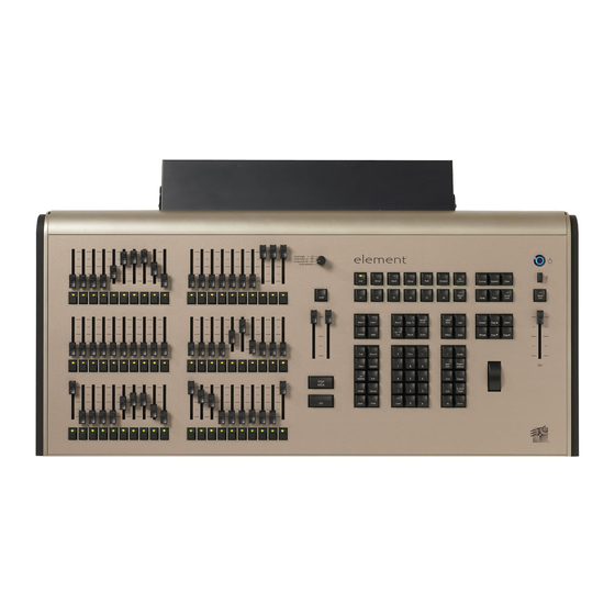
Page 24: Element Geography
Element Geography Below is a diagram of Element with references made to specific areas of use. The terms and names for each area and interface are used throughout this manual. Note: Element can support up to 2 monitors. For more information, see... - Page 25 The USB ports cannot be used for charging devices such as cell phones. External Monitors Element can support up to 2 display port, DVI-I, or DVI-D monitors. Display port can use an active adapter to VGA, DVI, or HDMI. DVI-I can be converted to VGA with a passive adapter.
- Page 26 Navigation Keypad Used for quick access to the Live and Blind displays, tab selection, location, paging and navigation within displays. Fader Control Buttons The {Fader Control} softkey is used to access the fader control softkeys. Control softkeys include: {Manual Override}, {Rate}, {Release}, {Off}, {Assert}, {Go to Cue 0}, {Stop Effect}, {Freeze}, {Filter}, and {Timing Disable}.
- Page 27 Level Wheel Adjusts intensity for selected channels. It also provides scrolling and zoom functions in various modes. See Level Wheel (on page 155) for more information. Master Playback Controls The master playback fader pair is located to the left of the control keypad. The master is a split cross-fader pair.
-
Page 28: Cleaning Your Console
Element has two DMX ports. To output, connect one 5 pin XLR cable per port. The first port will default to outputting the first universe of DMX, addresses 1-512, and the second port to the second universe, outputting addresses 513-1024. - Page 29 a maximum of 1000 configurable submasters • 120 channel faders • Console Overview...
- Page 30 Eos Family v2.9.0 Operations Manual...
-
Page 31: System Basics
Chapter 2 System Basics About System Basics The Central Information Area (CIA) Browser Softkeys Displays Display Control and Navigation Live and Blind Displays Playback Status Display Using Direct Selects Moving Light Controls Fader Configuration Virtual Keyboard sACN Output Viewer System Basics... -
Page 32: About System Basics
This will provide power to all internal electronics. Press the power button, located on the face panel. The button LED will illuminate blue to indicate the console is running. The console will boot up into the Element environment. The system is now ready for use. - Page 33 Favorite CIA Display You can select a favorite default display for the CIA that will show when [Displays] is pressed. The standard default display for the CIA is the Browser. The favorite display will show a gold star icon at the top of the CIA by the arrow and lock icons. Displays that can be selected as a favorite, but are currently not, will show a gray star at the top of the CIA.
- Page 34 When collapsed, only the {All NPs}, {All Speed}, and {Expand Arrow} buttons will be displayed. Labeling [Label] is used to attach an alphanumeric label to an object such as cues, channels, submasters, etc. Eos Family v2.9.0 Operations Manual...
-
Page 35: Browser
[Label] [Label] when appended to a record target command, clears the current label. This includes show file labels. Editing Labels The page arrow keys on the console or an external alphanumeric keyboard can be used to move the cursor within a label to aid in editing. [Page p] - takes the cursor to the beginning of the label. - Page 36 From this menu you can select one of the available clear options by clicking on the desired button in the CIA. Element will ask you for a confirmation before performing the selected clear. For {Clear Targets}, Element will allow you to choose which record targets you want to clear.
-
Page 37: Softkeys
[Escape] again. Softkeys Some of the features and displays in Element are accessible from the softkeys, which are located under the Browser. Softkeys are indicated in documentation with bold {braces}. The softkeys are context sensitive, therefore they repaint to display softkeys relevant to the display or command you are working with. - Page 38 They are viewed in tabs. Element has the ability to have one of three different workspaces active on individual monitors, as well as to have up to four frames in use in any workspace. Each frame can hold multiple tabs.
- Page 39 Note: From an alphanumeric keyboard, hold down either of the bracket buttons ([ or ]) and type in the number of the workspace you wish to view. For example, hold down [ and press 2 to view workspace 2. Frames Each workspace can have up to four frames in its layout. The number of frames in a workspace layout is determined by choosing the layout options offered in the Home Screen.
- Page 40 9 Pixel Maps 19 Snapshots 29 About 100 User Manual Command His- 10 Pixel Preview 20 Park tory Display Tabs The following displays can be selected, and they will open in a new tab in the selected frame: The following displays can have multiple instances open: Channel (Summary) •...
- Page 41 Tab Tools Every frame has a tab tools menu in the lower left corner of the frame. Selecting this menu icon will open the tab tools menu, which provides options for opening and closing tabs in that frame. You can left click with a mouse or double tap a tab in focus to also see this menu. The following is a list of menu options.
-
Page 42: Display Control And Navigation
Reset Columns - resets all of the column widths in the selected tab to Eos defaults. This • option will only be available for displays with columns. Lock Frame - prevents any additional tabs from being opened in the selected frame. •... - Page 43 Browser • Magic Sheet • Workspace • Command History • Curves • Pixel Maps • Show Control • Mirror • Any of these softkeys will open the associated display with a single press. Closing Displays To close any tab display, select the display by using the [Tab] key or other means of navigation. When the desired display is active, press [Escape] to close it.
- Page 44 Control Tabs Layout Options These tools offer you greater flexibility in the number of tabs you can view in any given workspace. A workspace can have up to four frames. Selecting a layout icon will assign the frame layout identified in the icon. Once a layout is assigned, you can select which displays and controls will be in which frames.
- Page 45 Close All Tabs In This Workspace Select this icon to close all of the tabs in the active workspace on this monitor only. Reset This Workspace This icon will close all of the tabs and frames and will reset the layout for the active workspace to a single frame displaying theWorkspace Layout Menu, from which you can select new tabs to open.
- Page 46 Single Monitor Snapshots The snapshots displayed here are single monitor-only snapshots recorded for the visible About Snapshots (on page 338) workspace. For information about snapshots, see . These snapshots can be recalled from any selected monitor from the Workspace Layout Menu. You can recall a monitor-only snapshot from the command line by using the syntax [Snapshot] [n] [Enter].
- Page 47 Selecting Displays When a display is selected, the screen is highlighted in a gold border and the display name (such as “1. Live Channel”) will be in gold as well. When a display is not selected, there is no border and the tab name is gray.
- Page 48 Magic Sheet List • Park Address List • Patch Display • Spreadsheet Display • Macro List • Quick Access Quick Access tools are available at the top of each display. There are three icons: Wand - popup magic sheet • Moving Light Beams - popup moving light controls •...
-
Page 49: Live And Blind Displays
You can lock this mode by holding [About] and double tapping [Time]. When in display time mode, “Display Timing” will display in the upper left of the live display. To exit this mode, press [About] again. [Data] Key Pressing and holding [Data] allows you to view the values behind any referenced or marked data. - Page 50 In Live, table view displays all active channel data being output from Element. In Blind, it will display all data for a single record target (cue, preset, palette) depending on what is viewed. In table view, focus, color, and beam information can be viewed in either a summary of these three categories or an expanded view to show all parameter data.
- Page 51 In the table, a slight space is provided between fixture types, giving a clear delineation between them. The name of the fixture type is displayed at the top of the section for that fixture. Channels with only intensity parameters will display the same as in summary view. Preview Mode in Live A {Preview} softkey is available when in Live Summary.
- Page 52 Channels in Use To open the Channels in Use display, click on the {CIU} icon in the home screen or press [Tab] & [3][2]. A Channels in Use display shows the following information for each channel: Number of cues the channel appears in. •...
- Page 53 Live and Blind Configuration Menu (on page 46) Indicators in the Live/ Blind Display Element relies on many traditional ETC indicators which you may be familiar with, as well as some new ones. This section identifies the conventions used in Element to indicate conditions to you.
- Page 54 Conventionals Conventions display only the top field, intensity, as no other parameters are available on a conventional channel. Moving Lights or Multi-parameter Devices This view also has additional data fields beneath intensity (F, C, B). This information can be suppressed by pressing and holding [Data] and any of the parameter buttons in the parameter display (Focus, Color, Image, Shutter, or Form).
- Page 55 Multicell Devices Parameter data can also be suppressed in the same way as moving lights. You can use flexichannel modes to hide cells or master channels. See Using Flexichannel (on page 47) for more information. When in Flexi Cells Off mode, the master channel will display its own information in the normal font size, and data indicators will be used for the cells.
- Page 56 When using Flexi Cells off in table view, plus signs are also used to indicate a difference in the cells. Color Indicators Element uses color to indicate the selection state and information about channel/parameter levels. Channel Numbers/ Channel Headers Gray number Unpatched channel number.
- Page 57 Channel/ Parameter Levels Bright Red Manual Data (any data that has been set but not yet stored to an active cue or • submaster) on all consoles using the same user ID. When manual channels are used, there will be an advisory that says "Manual Channels" in red in the upper left hand corner of any Live display.
- Page 58 IP, CP, FP, BP Indicates that the value is referenced to a palette (Intensity, Color, Focus, or • Beam). This text is followed by a number, indicating which palette is being referenced. This can be substituted with the palette label if the “Show Reference Label” setting is Show Reference Labels (on page 144) activated (see ).
- Page 59 MC Line Wrap - When enabled, this option keeps all of the cells together of a multicell • fixture when viewing it in Live summary view instead of breaking them up across multiple rows. Suppress Target Labels - Hides the Label column in Blind spreadsheet view. •...
- Page 60 All channels • All patched channels • Manual channels • All show channels (any channels that have data stored in a cue or submaster) • Active channels (channels with intensity above zero or a move instruction) • In Use Channels (channels with intensities that are above zero or fading to zero, running •...
-
Page 61: Playback Status Display
Flexichannel with Timing You may also engage the “channels with timing” flexichannel state by pressing [Flexi] & [Time]. This will display all channels that have discrete timing in the current cue and will remove channels without discrete timing from view. The display will remain in this state until you disengage it by pressing [Flexi] again. - Page 62 PSD visible showing that cue list, nothing will be paged. Indicators in the Playback Status Display Element relies on many traditional ETC indicators which you may be familiar with, as well as some new ones. This section identifies the graphical and colorful conventions used in Element to indicate conditions to you.
- Page 63 Color indicators Cue List Gold - Any item (cue, list, page) highlighted in gold indicates “current”. • Outlined in gold indicates “selected”. Red - Cue fade is in progress • Text indicators * - Indicates a link to a non-existent cue. Found in the cue display "Link" area. •...
- Page 64 Note: If any show control options are currently enabled in Setup>System>Show Control, they will display at the top of the Playback Status Display. For more details on information contained in the playback status display, see Playback Status Display (on page 49) Playback Status Display Configuration Playback Status Display (PSD) has a configuration menu, which is accessed by double clicking or right-clicking on the PSD tab, or by selecting the gear icon, and clicking PSD.
-
Page 65: Using Direct Selects
Reorder Columns Reorder columns allows you choose what data displays in the PSD and what order it displays in. By default, all columns except notes will be displayed. The arrow keys on the right can be used to move columns around. Columns are moved in groups. To select a column header to move, click or tap the name. - Page 66 Snapshots - red • Magic Sheets - magenta • Scenes - green • Custom - light gray • If there are more items than can be viewed at once, you may view subsequent pages by using the page touchbuttons ({ }, { }) by the direct selects.
- Page 67 The following options are available: # of Banks - sets the number of direct select banks that will display. • Layout 25, 50, 100, 200 - allows you to select the number of buttons that will display per bank. • Rows - allows you to select the number of rows in the banks.
- Page 68 Maximize Button Size - sets the size of the direct select buttons to fill the available space. • This is similar to Fit to Screen in previous versions of software. Reset to Default - will restore the settings to the default state. If no default state has been •...
- Page 69 From the configuration window, you can select the target type of scene, and the scene number. Only one scene can be assigned at a time. From the command line, you can select a scene, such as [Cue] [1] {Attributes} {Scene} [1] [Enter].
- Page 70 From the configuration window, you can select the target type of scene, and the scene number. Only one scene can be assigned at a time. From the command line, you can select a scene, such as [Cue] [1] {Attributes} {Scene} [1] [Enter].
-
Page 71: Moving Light Controls
Note: A single empty direct select tile may remain if the adjacent direct select tiles are not sequential. This is to allow an easy way to insert a new direct select between the existing ones. [Shift] & Direct Select Selecting record targets from direct selects will terminate the command line. To post a control to the command line without terminating it, hold down [Shift] while pressing the direct select. -
Page 72: Fader Configuration
Palette or Preset button (Clicking the button will put the palette or preset on the command line.) Fader Configuration The fader configuration display is found on Tab 36 .The Fader List (on page 62) , which shows all of the faders and their assignments, can be found in Tab 35. At the top of the fader configuration display, you can select the fader page, which has 100 pages of 10 faders each page. - Page 73 Target This setting allows you to map a submaster, intensity, focus, color, or beam palette, preset, global effect fader, manual time master, or grandmaster to a fader. This sets the number of the target assigned to the fader, such as Preset 2 or Submaster 5. For a list of available Target IDs, click or press the {...} button beside ID.
- Page 74 Manual Time Master (on page 64) • Indicators in the Element Fader Status Display Each fader is color coded based on its assigned target type. Channel faders are orange. Grandmasters and inhibitive submasters are in red, additive submasters are yellow ,and presets, palettes, global effects, and manual time masters are brown.
- Page 75 You can also make changes to a fader's configuration while in the fader list display by clicking on a column. A virtual fader will be displayed. Click on the appropriate area of the fader to access the configuration options. Selection can be done by clicking in the column or from the command line.
- Page 76 Manual Time Master A fader can be mapped as a manual time master. Note: Manual Time Master applies to changes made manually, not to playback. A manual time master can be used to impact any manual control timing. For a manual time master, you need to assign a minimum and maximum time settings to the fader.
- Page 77 Master Only Master Only is a fader option that can be assigned in the fader configuration display (Tab 36) or in the fader list (Tab 35) for submasters, presets, and palette faders. Submasters can also be configured in the Submaster List (Tab 15). Master Only faders are used to set a level for content to fade to.
- Page 78 Clearing Channel and Parameter Filters Press the red [X] to clear the channel or parameter filters listed. Virtual Fader Module A virtual fader module can be opened from the home screen by selecting the Faders button or by pressing [Tab] [2][8]. The virtual fader module has a configuration menu, which is accessed by first selecting the module tab and then double clicking on the tab to open the menu.
-
Page 79: Virtual Keyboard
1 and places it in fader 4. Levels, effects, and labels are not copied when using the {Attrs Only} softkey. Virtual Keyboard It is possible to open a keyboard which mimics the hard keys found on the actual Element keypad. To open, you can select the virtual keyboard from the Workspace Layout Menu (on page 31) - Page 80 The left side of the viewer is the universe grid. It displays 512 address cells. Cells outlined in a color are currently patched addresses. Each patched cell contains an address number and output value. Unpatched cells are black and only have an address level. Output values are 0 through 255.
-
Page 81: Managing Show Files
Chapter 3 Managing Show Files About Managing Show Files Create a New Show File Open an Existing Show File Merging Show Files Printing a Show File Saving the Current Show File Importing Show Files Exporting a Show File Exporting Logs Deleting a File File Manager Managing Show Files... -
Page 82: About Managing Show Files
Press {OK} to confirm or {Cancel} to discontinue the operation. In Element, a new show file defaults to a 1-to-1 patch, which will have a 1-to-1 patch and 1-to-1 channel to sub assignment. Clicking {Patch 1to1} will deselect the option and result in a blank patch. - Page 83 (selected). To stop the show load process, press the {Cancel} button. When you have selected/deselected all of the show components you require, press the {OK} button. Element loads the selected show to the console. CAUTION: On a partial show open, if any record targets are not opened, any existing data of that type will be cleared from the console.To merge show data, merge...
- Page 84 As you specify components, they are added to a table in the CIA. In the table, fields with a dark background may be edited, fields with a light gray background do not apply to that component. For each component in the list, you can specify the desired range by pressing the proper area in the table and entering numbers from the keypad.
-
Page 85: Merging Show Files
USB device. To merge a show file, navigate within the Browser to: File> Merge>. Navigate to the desired storage location and press [Select]. When using merge, Element displays only the available files. Navigate to the specific file and press [Select]. - Page 86 If you select the {Advanced} button in the merge show loading screen, you will have the opportunity to load partial components from the show file and be able to specify the desired location of those partial components in the current show file. For example, you could specify only cues 5-10 and load them as cues 20-25 in the current show.
-
Page 87: Printing A Show File
Printing a Show File Element provides you with the ability to save a show file or aspects from a show file to a PDF file for printing. Element has three locations to save the PDF files including the Show File Archive, the File Server (if connected), or a USB device (if connected). - Page 88 This will open the printing screen in the CIA. From this screen you can choose which aspects of the show file you want to save to PDF. By default all aspects are selected (gray) and will be saved. To withhold any show aspects from printing, simply deselect them in the CIA by touching the respective button.
-
Page 89: Saving The Current Show File
Note: In the {Advanced} view, you can use the [Thru] key to jump to the End column. To deselect all show aspects, press the {Reset} button and all buttons will return to black (deselected). To return to the main print screen, press the {Return} button. To stop the show file from being saved to a PDF file and return to the browser, press the {Cancel} button. - Page 90 Browser to: File> Save As> and press [Select]. Element provides you with three locations to save an Eos Family show file (.esf) including the Show File Archive, the File Server (if connected) or a USB device (if connected).
-
Page 91: Importing Show Files
If you are importing an USITT ASCII file, you will have two options, Import as Library Fixtures or Import As Custom Fixtures. Import as Library Fixtures will allow Element to try to match the fixtures in the file with •... - Page 92 You can select starting and ending channels for the import. Mapping You can map Element patch fields to fields in the Lightwright file. Channel and Address must be mapped for the file import to work. Any other field can be set to ignore if desired. Once a Lightwright field has been mapped, it will display in grey in the dropdown menu.
-
Page 93: Exporting A Show File
Note: Element does not currently support multiple gels per fixture from Lightwright. Address Formats Element will accept mulitple address formats for importing. Examples of those formats are 2/3, 2.3, 2,3, 2-3. Element will convert all formats to n/n. Device Mapping Devices can also be mapped. -
Page 94: Exporting Logs
An exporting logs message will appear while the log files are being created. Deleting a File Element provides you with the ability to delete show files from the Show File Archive and the File Server from within the Browser. To Delete a Show File Navigate within the Browser to: File>... -
Page 95: File Manager
Navigate within the Browser to: File> Open and press [Select]. Navigate to the desired folder and press [Delete]. Press [Enter] to confirm or any other key to abort the deletion process. File Manager Element has a File Manager (on page 420) , which also provides a way to manage show files. - Page 96 Eos Family v2.9.0 Operations Manual...
-
Page 97: Patch
Chapter 4 Patch About Patch Patch Main Displays Patching Conventional Fixtures Patching Moving Lights, LEDs, and Accessories Patching Multicell Fixtures Labeling Using the Scroller/Wheel Picker and Editor Settings in Patch Using Device List Clearing the Patch Update Profile Fixture Editor Patch... -
Page 98: About Patch
Creating multipart and compound channels (on page 93) When you open a new show file, Element can create a 1-to-1 patch. This means that the patch will automatically have channel 1 patched to address 1, channel 2 to address 2, and so on up to the maximum channel count of your console. -
Page 99: Patch Main Displays
Element defaults to patch by channel mode. Pressing [Format] while in the Patch display will toggle the mode between patch by channel and patch by address. The patch screen will display the following information if available: Channel - the patched channel number. -
Page 100: Patching Conventional Fixtures
For patching fixtures, there are two different patch modes: Patching By Address (on the facing page) . Element defaults to patch by channel mode. Pressing [Format] while in the patch display will toggle the mode between patch by channel and patch by address. - Page 101 [2][0][3] [At] [1][2] [Enter] - patches address 203 to channel 12. • Note: If, at any point, you try to patch an address that is already in use, Element will post an advisory to indicate this, preventing you from duplicating addresses in your patch.
- Page 102 Replace By default, if you patch an address to a channel that is already patched, Element will create a new part for the new address. If you want to replace the current address with the new, use {Replace}: [n] {Replace} [n] [Enter] - replaces the address in part 1 of the selected channel.
- Page 103 Example: Let’s assume you patch 96 channels of dimmers to addresses 1 through 96. [1] [Thru] [9] [6] [At] [1] [Enter] • Now you wish to dimmer double 1 through 12 of your Sensor+ rack and you want these to be channels 97 through 108. To patch this, press: [9] [7] [Thru] [1] [0] [8] [At] [1] {B} [Enter] •...
- Page 104 [Copy To] {Only Show} - copies a channel to another location with all record targets in the • show but not the patch data. [Copy To] {Only Text} - copies only the notes and keyword fields from one channel to •...
- Page 105 By default, Element will add a part if you are trying to patch to a channel that has already been assigned an address.
-
Page 106: Patching Moving Lights, Leds, And Accessories
This will perform the same action as the previous example, assuming channel 8 was previously patched to an address. To select multiple parts for editing: [1] [Part] [1] [Thru] [5] • This is useful for deleting or assigning new addresses to existing parts. To patch a compound channel in channel format: [1] [Part] [2] [At] [5] {Type} <scroller profile>... -
Page 107: Patching Multicell Fixtures
In the search window, press {Parameters} to view a parameter list for a fixture, or press {Fixture Notes} to see any notes that exist for it. You can also view this information in the Fixture Editor. Press [At] and then enter a starting address for the selected channel or group of channels. The desk will automatically offset addresses based on the fixture type selected. - Page 108 When these devices are patched, they will patch a master channel with a whole number for a channel number and the appropriate number of additional cells, which will have point numbers for their channel numbers. [1][0] [At] [5] [Enter] - patches channel 10 and all of its cells starting at address 5. •...
- Page 109 On the right, you can see the full personality of the selected multicell fixture. If you have the whole fixture selected, you will be able to see all of the parameters for each cell and the master but changes cannot be made here. Editing Multicell Fixtures You will need to select the master or cell profile to edit parameters.
-
Page 110: Labeling
To change specific cell data such as DMX offset, you will need to use {Edit Multicell}. With a multicell fixture or a master cell selected in the fixture editor, press {Edit Multicell}. In the Edit Multicell window, you can edit cell numbers, DMX offset, and mastered cells for each cell. Once you are finished editing, press {Save Fixture} to save your changes or {Cancel Edit} to remove the changes and exit the edit mode. - Page 111 In the above image, {ETC Scroll} is the default scroll for the selected ETC Source Four Revolution. The list of gel colors as they are installed in the scroll are displayed to the left with a color chip for easy reference.
- Page 112 Creating a new scroll or wheel When you create a new scroll or wheel, {New Wheel n} appears in the wheel list as the selected button. The frame list will be empty with only “New” displayed in frame 1. You can label the new wheel by pressing [Label] and typing the desired label on the virtual keyboard and pressing {Enter}.
- Page 113 Editing a copy of a scroll or wheel If a copy has been made of an existing scroll or wheel, the copied scroll or wheel will display as {New Wheel n} before the standard manufacturer offerings. The frame list will include an exact duplicate of the copied selection.
- Page 114 Scroller Fan Curves Curves can be applied to the scroller fan parameter allowing for the output of the fan to be controlled by the intensity of the channel. The curves available for this are the same used for Applying a Curve To Scroller Fans (on page 335) intensity parameters and cues.
- Page 115 The displayed calibration information is the DMX level that puts the frame into its center position. Information in the calibration column can be manually edited by clicking on it and typing in a new DMX level. Note: Calibration data will only be applied to scroller wheels that are assigned to a channel.
-
Page 116: Settings In Patch
When creating and editing your patch, page through each of these softkeys individually to enter more specific data about your selected device. {Patch} Display and Settings With patch open, Element defaults to this display. It provides access to data input fields that you may use to define devices in your lighting system. Note: The Artnet and sACN offset will display here. - Page 117 • port and offset value.You may enter a start address without defining an end address. Element will draw this information from the library data. If you wish to leave a larger • output gap than required by the library, use {Offset}. See Using {Offset} in Patch (on page 93)
- Page 118 {Preheat} - This field allows you to specify an intensity value to preheat incandescent • filaments. When a preheat flag is applied to a cue, any channels that are fading from zero to an active intensity and have been assigned a preheat value in patch will preheat in the immediately preceding cue.
- Page 119 {Invert Pan} {Invert Tilt} - A moving light attribute used to invert the output of pan, tilt, or • both. Select either the {Invert Tilt} or the {Invert Pan} button on the CIA. [2] {Attributes} {Invert Pan} - inverts the output of the pan parameter on channel 2. •...
- Page 120 {Text} - Text fields are used to provide up to ten keywords about any channel or group of • channels. These fields can be anything that you think is important about a channel, such as its location (FOH), an attribute of it (wash, spot) or other characteristics of the channel (such as gel R80).
-
Page 121: Using Device List
Renaming Text Fields in Patch You can rename the text fields. By default, the text fields are named {Text 1} through {Text 10}. Text fields 1 through 10 display in the Patch display. Renaming those fields will rename the columns associated with them in the Patch display. {Text 1} [Label] <Position>... - Page 122 Note: The System ID number from CEM3 is not currently supported. Note: Rack numbers and dimmer numbers need to be unique for Element to properly recognize them. For CEM+, dimmers also need to be patched to different sACN addresses. With a dimmer or dimmers selected, you can edit various dimmer settings in the property view, which will display in the CIA.
- Page 123 ECU tab. By default RDM is disabled. See page 416) If using Network RDM, this must be done via an ETC Net3 Gateway and RDM must also be enabled on the DMX ports of the Gateway. The Gateway needs to be running version 5.1 or newer.
- Page 124 Footprint • Element will also display what personality from the library the device matches in the Eos Type column. This information will not display until you first select the device. Once the device has been selected for the first time, Element will extract the type information from the device and display it.
- Page 125 Patching Discovered Dimmers and RDM Devices When dimmers/devices are discovered, they are not automatically attached to any patched channels in Element. If you want the benefits of dimmer or RDM feedback, you must attach a dimmer or device to a channel.
- Page 126 Errors and Warnings One of the advantages of using dimmer and RDM feedback is error and warning reporting. If something happens with a patched and attached dimmer/ device, you will be notified in live, patch, and about. Errors can be viewed in the About Channel and About Address displays. The notifications you can see are: A red “!”...
-
Page 127: Clearing The Patch
{Cancel} from the confirmation screen. Update Profile When a new library is installed on Element either from a software update or a separate fixture library file from the ETC website, changes in library data will not automatically update your show files. - Page 128 The fixture creator is accessible from patch. Once a fixture has been created, it is stored in the show file. It is not added to the fixture library. If you want to use the created fixture in another show file, you will need to use merge. See Merging Custom Fixtures into a New Show File (on page 129) If you would like to remove any unused fixtures from this list, press {Delete Unused}.
- Page 129 Use the [Page] keys, mouse, or touchscreen to select the new fixture. Select the parameter list by clicking on it or touching it. Determine the total number of parameters that your fixture has. Do not count 16-bit parameters as two parameters, this will be done in a later step. Press {New} or {+} to add parameter slots.
- Page 130 If you are missing a parameter slot: At any point you can use the [Page] keys and {Insert}, to insert a parameter slot above the selected one. If you want to remove a parameter: you can use the [Page] keys and {Delete}, to remove a parameter from the list.
- Page 131 Range editing a parameter You can enter the operational ranges for specific slots within any specific parameter (such as color scroller, color wheel, gobo wheel, and so on). You can do this by either defining each range individually or you can use the quick action tools to define multiple ranges at once.
- Page 132 • ranges. The console then distributes the DMX values and assigns a user range exactly as any of the wheel or frame parameters are automatically created. (Frames 1, 2, 3, etc would be represented as 0.5-1.4, 1.5-2.4, 2.5-3.4, etc) Matched - The user values are set to match the DMX values. This is required for a •...
- Page 133 Units • Degrees • Percent • (none) • Labels • Open • Open/Color N • Blackout • Animation • Animation N • Color • Color N • Color N/N • Color N/Open • Effect • Effect N • Gobo • Gobo N •...
- Page 134 Note: When adding a new mode, you will need to first add the parameter that the mode needs to be associated with before you will be able to assign the mode. See Creating Modes (on the facing page). Modes can be edited in the range editor.
- Page 135 Note: A single range parameter is not useful as a condition so those will not be available for selection. Note: Some fixtures use virtual modes. Those are modes without a DMX address assigned to them. Creating Modes Let's take a look at how to create modes for a gobo wheel. This gobo wheel can be indexed or rotated.
- Page 136 Click in the mode cell to open the mode selection window. This window will display all possible conditions that can be applied to your fixture. In this case, there are only two possible. If a parameter has multiple ranges and is selected as a condition for a mode parameter, all the ranges for that parameter must be used.
- Page 137 Once the modes are created using the index and rotate ranges, the gobo wheel mode parameter will be read only. The range editor for gobo wheel mode will give an advisory saying which mode the ranges are used in. If changes are needed to those ranges, press {Remove as Mode} in the range editor.
- Page 138 Level - the 0-255 level of the parameter. • Snap Parameters Certain parameters may not want to be subjected to cue timing. Those parameters can be set to snap. By default, Element will snap the parameters listed in the following table: Beam FX Effect Library MSpeed...
- Page 139 Save Fixture Unsaved fixture profiles will have a red background in the fixture editor. Press {Save Fixture} to store the new profile, or {Cancel Edit} to exit out and not save your changes. Note: If you leave the patch display without saving or using {Cancel Edit}, an advisory will display above the command line letting you know that you have unsaved data.
- Page 140 Create Multicell With the new fixture selected, press {Create Multicell}. Press {+} to add cells. This will open a fixture list display. Only fixtures added to your fixture list will be here. Select a fixture, a cell profile from an existing multicell fixture, or create a new cell profile by selecting + Add New Cell Profile.
- Page 141 Editing Fixtures You can view and edit existing fixtures in the Fixture Editor. Edited fixtures will display with an "*" beside their name. With the fixture selected, you can change the name by pressing [Label] or tapping on the fixture. You can press [Label] twice to clear the name. The virtual keyboard will open in the CIA. The fixture's name as it is in the library will still display by the new name.
- Page 142 Eos Family v2.9.0 Operations Manual...
-
Page 143: Setup
Chapter 5 Setup About Setup System User Device Console Status Display Setup... -
Page 144: About Setup
{Num of Channels} You may use this field to set the number of channels in your Element up to 10,000. However, you are limited to only patch up to the number of channels that are available from your system, either 250 or 500 depending on the channel count for your Element. - Page 145 {Dim. Dbl. Offset} This allows you to set the address offset for dimmer doubling. The default for this is 20000, to match the Net2 standard offset, including Sensor dimming software. For dimmer doubling over Local DMX, this value should be set to 256. {Create Virtual HSB} {Create Virtual HSB} allows you to disable creation of virtual hue and saturation parameters.
- Page 146 The categories for which you may set default times are: Intensity Up • Intensity Down • Color • Focus • Beam • Show Control Setup This section allows you to adjust settings for MIDI show control, time code (MIDI or SMPTE), analog, and serial functions.
- Page 147 {MSC Rx Device ID} This setting allows you to choose the devices from which the console will receive MSC. When set, the console will respond to MSC data from any Net3 gateway that has a matching “ACN MSC Rx ID.” Gateways will send the MIDI data over an ACN connection. When built-in MIDI ports are available, the setting needs to match or at least contain the MSC Rx ID.
- Page 148 Example: {MIDI Tx Source ID} [2][5] [Enter] • MIDI - MTC {MIDI Time Code Rx} As above, but for MIDI Time Code instead of SMPTE. Defaults to “Enabled." Contacts {Analog Inputs} This is a master setting for receiving analog inputs from a Net3 I/O Gateway or the built-in I/O port (when available).
- Page 149 Multiple ports can be assigned. A space needs to be used to separate the addresses. Note: ETC recommends using 8000 and 8001 respectively for port numbers. Remember that when setting port numbers on your external device that they should be set to the opposite of what Eos is set.
- Page 150 {String RX Source IDs} This setting allows you to choose the Net3 I/O Gateways through which the console will receive serial strings. When set, the console will receive serial from any Net3 I/O Gateway that has a matching “ACN Serial Group ID.” The gateway will send serial data over an ACN connection to the console.
- Page 151 Note: Changes to these settings may require a restart. When required, a warning message indicating a needed restart will display. Local DMX The following settings are available: Enable - enables DMX output from the local DMX ports. • Default Output Protocol - enables DMX as a default output. •...
-
Page 152: User
Off Time • Release Time • Record Confirm • Delete Confirm • Cue Only • Auto Playback • Plus % • Minus % • Level • Update Defaults (all) • Partition • Highlight • Lowlight • Highlight Remdim • Live Remdim Level •... - Page 153 Delete Confirm This field allows you to enable/ disable a required confirmation before any delete command is executed. The default is “Enabled”. Auto Playback When enabled, this feature automatically plays back cues and submasters as they are stored and releases manual control. For submasters to automatically play back, the slider must be at full.
-
Page 154: Device
Highlight Rem Dim - This enables a remainder dim when in highlight mode, thereby • temporarily dimming any channel not participating in the High/Low. An intensity level or a preset can be assigned in this field. Channels not in highlight or lowlight that are not included in the preset are not affected. - Page 155 {Visible to Remotes} {Visible to Remotes} allows your console to be automatically detected by the application. If not used, you will need to manually configure a connection to your console. Note: If using {Visible to Remotes}, the application will identify the consoles by their name and IP address, so it is useful to know the device names and addresses to ensure that you are connecting to the right one.
- Page 156 {Use Shift as Eos Shift} - allows the SHIFT key on an alphanumeric keyboard to be used as • the console's [Shift] key. If not selected, the Z key on an alphanumeric keyboard will function as the [Shift] key. Volume Level Note: External speakers are required for playing sounds.
- Page 157 Reset This button resets all three trackball settings back to their default. Brightness Settings This screen on Element allows you to adjust the light level for desk lamps, and the direct select brightness. Desk Lamp Desk lamps, such as Littlites, can be dimmed from within the software application. The {Desk Lamp} slider has a range of 0% (dimmest) to 100% (brightest).
-
Page 158: Console Status Display
If the slider is set to 0, the color coding for the direct selects is removed, and a yellow outline will display around valid palettes based on your fixture selection. PDF Settings This screen allows you to select the orientation and paper type for PDF files. Recall Device Settings When multiple devices are in a system, this option allows you to select a device to recall their settings. - Page 159 Memory Problems Memory Fragmentation / System Memory • Largest Free Block is under %1 MB. • RAM usage is at or above %1% (threshold %2%). • Application memory usage is at or above %1 (threshold %2), which is close to •...
- Page 160 Eos Family v2.9.0 Operations Manual...
-
Page 161: Basic Manual Control
Chapter 6 Basic Manual Control About Basic Manual Control Using Channel Faders Selecting Channels Setting Intensity Manual Control of Non-intensity Parameters (NPs) Home Multiple Intensity Channels Multicell Fixtures Lamp Controls Using [+%] and [-%] Remainder Dim Highlight and Lowlight Sneak Select Keys Channel Check Address at Level... -
Page 162: About Basic Manual Control
About Advanced Manual Control (on page 254) Using Channel Faders One way to bring up channel levels with Element is using the channel faders. The fader position switch is used to select between channels 1 through 40, channels 41 through 80, or channels 81 through 120. - Page 163 Note: When manual channels are used, there will be an advisory that says "Manual Channels" in red in the upper left hand corner of any Live display. Note: Selecting channels from the summary or table displays will start a new command line.
- Page 164 {Offset} [4] [Enter] -selects every fourth channel in the current channel selection. • [1] [Thru] [2] [4] {Offset} [4] [/] [4] [Enter] - selects channels 4, 8, 12, 16, 20, and 24. You • can select to offset by 2/2, 4/4, 3/3 etc. Eos Family v2.9.0 Operations Manual...
- Page 165 Channels are deselected when any action is taken on the keypad that is unrelated to manual control, such as recording groups and cues, or updating a record target, etc. You can also press [Clear] after a terminated command line to clear the channel selection.
-
Page 166: Setting Intensity
Note: {Select Last} is a fast way to regain your last channel selection. See Select Last (on page 173) Any manual control action taken while record or update is on the command line will automatically reselect your last channel selection. Setting Intensity Channel intensity may be manually entered from the keypad, set with an intensity palette (if programmed) or set with the level wheel. -
Page 167: Manual Control Of Non-Intensity Parameters (Nps)
You can continue manipulating the selected channels so long as the channels are selected and displayed on the command line. Level Wheel You may set intensity for selected channels or addresses using the level wheel. Rolling the level wheel upwards increases intensity. Rolling it downwards (towards you) decreases it. Manual Control of Non-intensity Parameters (NPs) Non-intensity parameters can be set with a variety of controls including the control keypad, buttons on the central information area (CIA) and the Moving Light Controls. - Page 168 Setting Parameters with the Keypad When the CIA is placed in parameter mode, all parameters of selected channels may be given numeric values through the keypad. When no channels are selected, the CIA shows all of the parameters that are available in the lighting system.
- Page 169 Color Spaces There are six color spaces that you can choose to work in. All of these spaces are connected. So it doesn't matter which space you wish to work in, the console will translate the information to work with your fixtures. When the color picker is first opened, the CIE xy color space and the gel picker will open by default.
- Page 170 For the CIE xy (CIE 1931) and CIE uv (CIE 1976), the triangle represents the RGB space as defined by the PLASA standard E1.54. Fixtures that comply to that standard can achieve any color within the triangle. The cone represents the color spectrum that we can see. Controls Each color space has three virtual encoders, a vertical encoder, a {?} button, and a {^} button.
- Page 171 Basic Manual Control...
- Page 172 {Brightest} - determines the color match used. This is helpful when working with fixtures • that have more than three color components, such as RGBA, RGBWm or ETC's fixtures. Pressing {Brightest} or {Shift} +a gel from the picker will cycle through the three modes.
- Page 173 How the Gel Picker Affects Scroller and Color Wheel When possible the Gel Picker will select the closest gel as defined in a scroller or color wheel. Note: Some devices contain manufacturer specified gel mixes, and will only allow selection from the Gel Picker of the exact gels in their list. The channel display will show the frame number and the corresponding label that is defined for that frame.
- Page 174 Color Path Note: Color path is only applicable for additive mixing systems. Color Path is a option for controlling color fades between cues. By default, color fades happen in the native space of the fixture. If you want a fade that resembles a fade in a different color space, you can do that using color paths.
- Page 175 • - plays / resumes the color fade. • - skips to the end of the color fade. You can also click on the color path preview bar to scrub to any point along the fade. Additional controls may be available based on the color path selected. For example, Color Path 7 has additional controls for Hue, Saturation, and Brightness.
-
Page 176: Home
Home On Element, the {Home} softkey, located in the ML Controls, allows you to home a specific parameter. Additionally, you may home all of a channel’s non-intensity parameters or home only a specific category (I, F, C, B). To home all parameters, use the {Home} button above {All NPs}, and to home specific categories, use that category's {Home} button. -
Page 177: Multiple Intensity Channels
Multiple Intensity Channels When a fixture with multiple intensity parameters is patched, Element assigns it a master intensity. The master intensity can be used to control the multiple intensities together. The master intensity is handled in the same way as the intensity of a single intensity channel. - Page 178 When you have selected a cell, if you apply data that does not apply to the master, Element understands to apply it to the cells instead. In the example above, IF the master had color parameters, this action would apply color data ONLY to the master.
-
Page 179: Lamp Controls
Example: Cell 2 of a fixture is currently selected. You can adjust the encoders for pan and tilt even if the master actually controls those parameters. The cell will send that information to the master. This allows for greater ease of control. The following are additional multicell syntax examples: [5] [.] [2] [+] [+] - pressing [+] twice will put channel on the command line. -
Page 180: Using [+%] And [-%]
Use [+%] and [-%] keys to incrementally change parameter values. To access this function on Element, press [Shift] & [+] or [Shift] & [-]. By default, the [+%] and [-%] keys are assigned a value of 10. This can be changed in Setup. - Page 181 Pressing [Rem Dim] again releases all channels from rem dim mode and restores the stage to its previous state. Using the [Next] and [Last] buttons releases the current selected channel from remainder dim mode and sets its intensity to zero, while selecting the next or last channel and continuing rem dim operation.
-
Page 182: Highlight And Lowlight
Channels 2 through 10 will be dimmed to 30. Highlight and Lowlight Element can be placed in Highlight mode. Channels selected while in this mode will either go to a default setting, or to a value provided by a highlight preset (established in setup, Manual Control (on page 141) - Page 183 Example: [Group] [1] {Highlight} [Enter] - places channels 1 through 5 in highlight. [Next] - specifies channel 1. 1 is in the highlight value. • 2 - 5 are in the lowlight value. • All other channels go to the defined rem dim level. •...
-
Page 184: Sneak
Sneak The [Sneak] command (when a destination is not provided) removes manual changes from selected channels and allows the channels to sneak back to their background states (cue or submaster instruction, if any).Sneaking channels to their previous state is similar to the Expression release function, except sneak has the ability to release in time. - Page 185 The {Select Last} softkey allows you to reselect whatever the previous channel selection was. This includes multiple channel selections, groups, etc. Using {Select Last}, Element will recall your last command line and leave it unterminated for further operation. This will work for a loop of the last five commands.
-
Page 186: Channel Check
On a completed command line, using [At] or {Select Last} after {Select Active} or {Select Manual} will post the numeric channel list to the command line. For example, cue 1 is active, and has channels 1 through 5 at full. Using the syntax, {Select Active}[Enter] [At] will post channels 1 through 5 onto the command line. -
Page 187: Address Check
Address Check Address check allows you to quickly step through all of your patched addresses. Address check differs from Address at Level (on the previous page) because it skips non-intensity parameters of patched addresses. Since address check follows the current flexichannel state, it can be used with all channels to identify unpatched channels, or with flexi-patched to only show the intensity addresses of patched channels. - Page 188 Eos Family v2.9.0 Operations Manual...
-
Page 189: Using Groups
Chapter 7 Using Groups About Groups Recording Groups Live Selecting Groups Opening the Group List Using Groups as a Channel Collector Using Groups... -
Page 190: About Groups
• select. Note: On Element, Record Only is accessed by pressing [Record] twice. Ordered Channels When recording groups, channels are ordered in the group based on their selection order when the group is stored. This ordering is useful when combined with [Next] and [Last] functions, and when applying effects to groups. - Page 191 When a group is previewed using the Group List, the display defaults to showing the ordered view. Channels can be reordered as needed from this list. Use the [Format] key to change to a numeric listing of channels. Example: [1] [0] [Thru] [2] [Record] [Group] [1] [Enter] •...
- Page 192 The following options are available as extensions of {Offset}. Options can be used together. These extensions can be used to create Subgroups (on the previous page) . To close the Offset display, press {Close}. Direction {Reverse} creates a group with the channels in the reverse order that they were selected •...
- Page 193 {Num Groups} creates a specified number of subgroups. • [1] [Thru] [1][2]{Num Groups} [3] [Enter] would create these 3 subgroups: (1,2,3,4) • (5,6,7,8) (9,10,11,12). Spacing {Jump} is used to skip over a specified number of channels. • [1] [Thru] [1][2]{Chan Per Group} [3] {Jump} [1] [Enter] would create these 3 subgroups •...
-
Page 194: Selecting Groups
Offset (on You can also use the {Offset} softkeys to aid in create of groups and subgroups. See page 179) for more information. Selecting Groups Groups may be selected from the control keypad or the direct selects. To select a group: [Group] [1] [Enter] - selects all channels in Group 1 •... -
Page 195: Using Groups As A Channel Collector
switched (channels will appear in numeric order from lowest to highest). This setting is important in defining next/last functionality within groups in live/blind. If left in numeric format, when using [Next]/[Last] group selection channels will be selected in numeric order. If left in ordered view, they will be selected based on their order of being stored to the group. - Page 196 Eos Family v2.9.0 Operations Manual...
-
Page 197: Using Fan
Chapter 8 Using Fan About Fan Fanning Parameter Data Fan From the Command Line Fanning References Fanning Timing and Delays Using Subgroups with Fan Using Fan... -
Page 198: About Fan
About Fan Fan provides the ability to spread parameter and timing values in a range across a channel selection set and have those values be evenly spaced. Fan is applied by channel selection or group order. By default, fan operation is from the start channel. When {Fan} is pressed after a channel selection, the softkeys will repaint to the following fan styles: {Center} - The middle channel in the order is set as the start and will remain unchanged,... -
Page 199: Fanning References
[1] [Thru] [5] [At] [1] <0> [Thru] [3] <0> {Fan} {Mirror} [Enter] - sets channel 1 to 30%, 2 to • 20%, 3 to 10%, 4 to 20%, and 5 to 30%. Fanning References When fanning references, such as palettes, if there are more than 2 reference lists are used then the data will be referenced data. - Page 200 Eos Family v2.9.0 Operations Manual...
-
Page 201: Automark
Chapter 9 AutoMark About Mark AutoMark AutoMark... -
Page 202: About Mark
About Mark Mark is an instruction that automates the process of presetting moving lights to their required state in a cue, prior to fading intensity up. This allows your moving lights to unobtrusively perform non-intensity parameter transitions in an inactive (darkened) state. AutoMark The AutoMark feature is a system default setting and can be turned off on a cue-by-cue basis if required. -
Page 203: Storing And Using Palettes
Chapter 10 Storing and Using Palettes About Palettes Palette Types Palette Options Storing Palettes Live Recalling Palettes Editing Palettes Live Editing Palettes in Blind Using By Type Palettes Removing Channels from a Palette Deleting Palettes Storing and Using Palettes... -
Page 204: About Palettes
{Locked} (on the facing page) • Element supports up to 1,000 palettes of each of the four types, which can be recorded as decimal (up to three places, 0.001) or whole number (up to 9,999.999). Palettes are automatically filtered into IFCB categories. Color data cannot be placed in beam palettes, intensity cannot be included in focus palettes, and so forth. -
Page 205: Palette Options
[Record], [Record Only] and using filters are the most common ways. When [Record] is used, Element will store the relevant parameter category data (intensity, focus, color or beam) for all channels that are not currently at their default value. - Page 206 Storing Palettes with [Record] The most common method to create palettes is to store them from Live. Palettes can be numbered from 0.001 through 9999.999, and each can be given a label. [Record] will store the relevant current parameter data for all channels with non-default data for the appropriate palette type, as modified by the filter settings.
- Page 207 [1] [Thru] [9] {Iris} {Zoom} [Record] {Beam Palette} [5] [Enter] - stores all zoom and iris data • for channels 1 through 9 to beam palette 5. [-] [5] [Record] {Beam Palette} [Next] [Label] <name> [Enter] - stores to the next •...
-
Page 208: Recalling Palettes
Example: If you want to store color data to color palette 4, press: [Record] • and then press the button in the bank of color palette direct selects that is labeled in the lower right corner with a light gray “4”. {Color Palette Direct Select Button 4} •... - Page 209 Recalled palettes will appear as manual data for the specified channels. That data will appear as abbreviations of the palette type (IP3 = Intensity Palette 3, FP8 = Focus Palette 8, and so on), or as the palette label if defined/enabled in the displays settings in Setup (see Show Reference Labels (on page 144) ).
-
Page 210: Editing Palettes Live
Editing Palettes Live If a palette is already recorded, [Record] replaces all existing data, unless channels have been excluded. [Record Only] is a selective store, therefore it adds data. Recording over a previously existing palette requires a confirmation, if confirmations are enabled in Setup. See Record Defaults (on page 140) It is also possible to [Update] to add manual changes to the record... - Page 211 Offset • Make Null • Make Absolute • Replace With • Query • Entering Blind Palette from Live [Blind] {Palette} [Enter] - pressing this will display the first recorded palette of the selected • type (Intensity, Focus, Color or Beam) in blind or return to the last palette of this type viewed in blind.
- Page 212 • through 5 to palettes 9 through14 respectively. You do not have to supply the end value for Element to perform the move. {Beam Palette} [1] [Thru] [5] [Enter] {Iris} [5] [0] {Replace With} [2] [5] [Enter] - for palettes •...
-
Page 213: Using By Type Palettes
While in the specific palette category list view, the {Edit} softkey is available for use. The {Edit} softkey opens a blind channel view of the selected palette and changes focus from the palette list. You can change the blind display to spreadsheet or table view by pressing the [Format] key. To copy a specific palette to a new palette: You can copy palettes within the list to another location in the list using [Copy To]. -
Page 214: Removing Channels From A Palette
[1] [0] [Thru] [2] [0] {Discrete} [Enter] - changes the levels for channels 10 through 20 to • discrete. If any of those channels are default, the lowest numbered tracking channel will become the new default channel. [5] [Thru] [8] [At] [Enter] - removes the discrete data for channels 5 through 8. They will •... -
Page 215: Storing And Using Presets
Chapter 11 Storing and Using Presets About Presets Preset Options Storing Presets Live Recalling Presets Effects In Presets Editing Presets Live Using the Preset List Editing Presets in Blind Using By Type Presets Removing Channels From a Preset Deleting Presets Presets and Palettes Fader Properties Storing and Using Presets... -
Page 216: About Presets
Element supports up to 1,000 presets, which can be recorded as decimal (up to three places, 0.001) or whole number (up to 9,999.999). They can contain absolute data and/ or a mix of IFCB palettes. - Page 217 When you record data to a preset live, the channels involved in that preset will then actually be in that preset. Note: To access [Preset] on Element, press [Shift] & [Intensity Palette] or use the {Preset} button in ML Controls. The following methods can be used to store presets using [Record]: [Record] [Preset] [5] [Label] [name] [Enter] - records all parameter data for all channels •...
-
Page 218: Recalling Presets
Recalling Presets Channels must be selected when recalling a preset. If a selected channel or parameter has no value in the preset, it will stay in its current position. If you want to recall all channels in a preset, you can press [Recall From] [Preset] [x]. Presets on direct selects will be highlighted if they are applicable for the current channel selection. -
Page 219: Editing Presets Live
Note: If used with submasters and cues, the data is not referenced. So if changes are made to the effect in the preset, the effect saved to the submasters and cues will remain unchanged. The preset list display has a column for effects. For more information, see Recording an Effect to a Preset (on page 299) Editing Presets Live... -
Page 220: Editing Presets In Blind
Opening the Preset List When you press the [Shift] & [Intensity Palette] twice, the preset list will open on a new tab (or brings the list view into focus if already open). You can also open the list view from the home Workspace Layout Menu (on page 31) screen. - Page 221 Press [Blind] {Preset x} - opens to the specific preset. • Press [Tab] & [2][6] - opens the preset list. • Press [Shift] & [Intensity Palette] twice and then {Edit} when a preset is selected in the list. • CAUTION: When editing presets in Blind, changes to presets are automatically stored.
-
Page 222: Using By Type Presets
[Preset] [1] [Thru] [5] {Move To} <Preset> [9] [Enter] - this will move presets 1 through 5 to • presets 9 through 14 respectively. You do not have to supply the end value for Element to perform the move. If presets 9 through 14 already exist you will be asked to confirm this move. -
Page 223: Removing Channels From A Preset
[3] {By Type} [Enter] - makes channel 3 the new default channel for that device type. If • another channel for that type was the default channel, its data will now be discrete. [1] [0] [Thru] [2] [0] {Discrete} [Enter] - changes the levels for channels 10 through 20 to •... -
Page 224: Presets And Palettes Fader Properties
[Delete] [Preset] [1] [Enter] • [Delete] [Preset] [1] [Thru] [5] [Enter] • Presets can be deleted from any screen, at any time. A confirmation is required to delete, unless Record Defaults (on page 140) confirmations have been disabled in Setup. See Presets and Palettes Fader Properties Presets and Palettes can be mapped to faders by using the fader configuration display. - Page 225 Priority The Independent setting for faders has been changed to priority. There are 10 levels of priority for faders. 1 is the lowest and 10 is the highest. faders can still be shielded, which means that their content is automatically made exclusive and can't be controlled by anything other than that fader and park, including by manual control.
- Page 226 bump again to fire it. Note: This option is for faders that are set to Intensity Master. Exclusions Those exclusions include: Exclude From Record - output is not recorded into any other record target. • Exclude From Grandmaster - content cannot be mastered by a grandmaster. •...
- Page 227 Start Stop Effect -starts the effect while ignoring dwell times. Will stop effects if any are • running. Button Disabled - no action is assigned to the button. • Solo - suppresses any intensity values not provided by the associated content while the •...
- Page 228 Eos Family v2.9.0 Operations Manual...
-
Page 229: Working With A Cue List
Chapter 12 Working with a Cue List About Cue List Basic Cueing Recording Cues in Live Using [Cue Only / Track] Move Fade Selective Storing Cues in Live Timing Assigning Cue Attributes Flags Using External Links Modifying Cues Live [Update] Recording and Editing Cues from Blind Deleting Cues Using The Cue List Index... -
Page 230: About Cue List
When cues are created, they are stored in a cue list. Basic Cueing In Setup, you determine if Element will operate in a Cue Only or Tracking mode. See Tracking vs. Cue Only (on page 6) By default, the system is set to tracking, therefore this section primarily addresses working in tracking mode. - Page 231 Release (on page 258) for more information. Element is a tracking console, meaning once something is recorded into the cue list, the cue list will always contain information about that channel/ parameter unless it is nulled, by using the {Make Null} command, released by using the {Release} command, or filtered using the parameter filters.
-
Page 232: Using [Cue Only / Track]
[Record Only] <Cue> [Next] [Enter] - stores only the manually set values into the next cue • in the list. [Record Only] [Cue] [3] [Enter] - stores only the manually set data into cue 3. • As with [Record], filters can further restrict stored data if deployed when using [Record Only]. About Filters (on page 250) Record and Record Only [+] [+] can be used to specify a range of cues when using [Record] and [Record Only]. -
Page 233: Move Fade
After cue 7, values will continue to track until a move instruction or block is encountered. Move Fade Element uses Move Fade philosophy. This means that only changing levels are executed from cue to cue, and also that those levels that are moving will continue to do so in their own time if you execute cues before previous cues are done fading. -
Page 234: Timing
Since Element is a tracking console, any channels not included in the selective store, but that do have values in the previous cue will track into the recorded cue. This is true even when the desk is in Cue Only mode. To remove intensity values that would otherwise track when on a selective Remainder Dim (on page 168) - Page 235 • The command line will show the time as: Setting Cue Level Timing Unless you specify otherwise, Element assigns default fade times to any cue you record. Default timing is designated in Setup ( Cue Settings (on page 133) ). Cue level timing can be applied when a cue is recorded or can be added or modified later.
- Page 236 Non-intensity Parameter Category Timing Timing can be also applied for Focus, Color and Beam parameter categories at a cue level. By default, FCB timing is the same as intensity upfade time. Once FCB timing is different than intensity upfade time, those times are no longer affected by intensity upfade changes. When you apply a time to an individual parameter category and that category has no movement, the time is displayed in gray.
-
Page 237: Assigning Cue Attributes
[channel list] {Color} [Time] [3] [Enter] - adds a time of 3 seconds to all of the color • parameters of the channel list that have a move instruction. {Focus} [Time] [7] [Enter] - assigns a time of 7 seconds for the focus attribute of all •... - Page 238 Note: Preheat is a flag. Please see Preheat (on page 232) for more information. Follow/ Hang A follow automatically activates the next cue in the sequence when the follow time of the associated cue has elapsed. The follow time begins counting from the moment the cue is executed.
- Page 239 Following is an example of using link: [Record] <Cue> [2] {Link/Loop} <Cue> [8] [Enter] - records the specified cue 2 and • provides a link to cue 8 in the cue list. When cue 2 is played back, the linked cue is loaded into the pending queue of the associated fader.
- Page 240 Rate The {Rate} softkey can be used to apply a rate adjustment to all timing in the cue. The default rate is 100%, which is real time. To slow a cue down, set the rate below 100%. To speed the cue up, set the rate above 100%.
- Page 241 To add a note to a cue: [Cue] [n] {Attributes} {Notes} • To add a note to the currently selected cue, you can use [Shift] & [Label]. You can use the virtual alphanumeric keyboard or an external keyboard to enter the desired text.
-
Page 242: Flags
You can create a scene and a scene end at the same time by using [Thru]. For example, [Cue] [1] [Thru] [5] {Scene} will add a scene to cue 1 and a scene end to cue 5. Update Using Scene End The {Scene End} softkey can also be used when updating the cues in a scene. - Page 243 NPs. I is displayed in the Block field. Auto-Block Element also supports an auto-block function. Auto-block can protect your cue data from unwanted changes. For example, in cue 5 you set channel 1 to 50%. It is stored as a move instruction.
-
Page 244: Using External Links
Channel level blocks are indicated in the cue list by a “b” and auto-blocks are indicated in the cue list by a “b”, representing a partial block. To remove auto-blocks, see Auto-block Cleanup (on page 243) Moves There are two types of moves, live and dark. A live move is a NPs move in a channel with an intensity that is zero in the previous cue, that moves above zero in the current cue. -
Page 245: Modifying Cues Live
Removing an External Link To remove an external link: [Cue] [5] {Execute} {external link option} [Enter] • Modifying Cues Live Recorded cues can be modified live. Assigning Cue Attributes (on page 225) (such as link, loop, label and so on) may be edited as well. The cue does not need to be active (played back) to change cue attributes. -
Page 246: [Update]
Note: Using [Record] will store all parameters of all non-default channels onstage. This means that all other cue data and submaster data will be included in the record action. Modifying Using Record Only You may modify a cue by using record only as well. Record only is similar to record except that it selectively stores only manually set values, preventing unwanted levels (such as from a submaster), from being recorded into the cue. - Page 247 “R” in superscript next to the channel’s intensity. By default, Element updates any referenced data that was included in the cue. Example: Cue 5 is recalled Live. It contains references to color palette 1 and preset 2. You make changes to channels included in these record targets.
- Page 248 updated in cue 5 will now be shown as absolute data. • [5] [Thru] [9] [Update] {Make Absolute} [Enter] - this will break only the references for • channels 5-9 and record their manual values to the cue. Other manual values will not be included in this update.
- Page 249 [Update] <Cue> [3] [Thru] [7] [Track] [Enter] - updates cues 3 through 7. Range updates • are subject to the normal rules of track/cue only in determining impact on subsequent cues. Using Trace {Trace} works just as Track does, except it allows changes to be tracked backwards through the cue list, until it sees a move instruction.
-
Page 250: Recording And Editing Cues From Blind
Example: If you are currently in cue 5 and you want to update through cue 10, you would use the following syntax: [Update] [Thru] <Cue> [10] <CueOnly/Track> [Enter] • Update [+] [+] can be used to specify a range of cues for updating. [+] can also be used with [Record] and [Record Only]. - Page 251 Example: Suppose you are in blind cue 5 and you make changes to channels 1 through 5: [1] [Thru] [5] [At] [5] <0> {Iris} [3] [5] [Enter] • Intensity goes to 50% and Iris to 35%. You decide to remove the Iris instruction: {Iris} [At] [Enter] •...
- Page 252 Editing From the Blind Spreadsheet The blind spreadsheet is another useful blind view of cue data. While in blind, press [Format] to access the spreadsheet. See Spreadsheet (Blind Only) (on page 40) for more information. In spreadsheet view, cues are listed on the y axis and channels/ parameters are displayed on the x axis.
-
Page 253: Deleting Cues
In the above example, if running in cue only mode, any tracked values in cue 2 become blocks (see Block (on page 231) ) or moves in cue 9, as well as any move instructions which now match the previous cue. Cues after cue 9 are affected based on the default setting of track/ cue only. Any values in the cue after cue 2 that tracked from moves in cue 2 are changed to move instructions. - Page 254 Note: {Priority} and {Background} are cue list attributes. See Cue List Properties (on page 244) for more information. Note: {Time Code} is an external link. See Using External Links (on page 232) for more information. Opening the Cue List Index You can access the cue list index by pressing [Cue] [Cue],[Tab] [1][6], or you can navigate within the browser to Record Target Lists >...
- Page 255 [Cue] [n] [/] {Partition} [n] [Enter] • To remove a partition from a cue list: [Cue] [n] [/] {Partition} [Enter] • Auto-block Cleanup {Autoblock Clean} is used to remove all auto-blocks from a single cue or cue range. {Autoblock Clean} is a softkey that will be posted when the cue list and/ or cue number are on the command line in the Cue List Index, Live, and Blind.
- Page 256 Display PSD Time Countdown - displays the cue category times countdown in the PSD as a • cue is fading. Reorder Columns Reorder columns allows you choose what data displays in the top and bottom halves of the Cue List Index and what order it displays in. To make changes to the top half, select {Cues}. To make changes to the bottom half, select {Cue List}.
- Page 257 HTP instruction is higher than the LTP value. When a cue from an HTP cue list is executed, Element determines if the intensity value when the cue is complete will be higher than the current setting. If so, the intensity will begin to fade from its current value to the required value in the incoming cue using the cue's upfade time.
- Page 258 Note: This behavior is relevant only to cues. If a submaster is going to provide a higher level, Element will wait until the value is matched before assuming control of the intensity. The following example illustrates the use of the {HTP/LTP} softkey in the cue list index: [Cue] [1] [/] {LTP/HTP} [Enter] - toggles the selected cue list between HTP/LTP behavior.
- Page 259 Restore Background - any background cue, submaster, and effect levels are restored • following background priority. Manual levels will not be restored. This setting uses the Release time. Go From Last Go From Last controls the behavior that happens when you press the [Go] button while in the last cue.
- Page 260 When a filter has been applied, an indicator will display in the fader ribbon. C will display for channel filter, and F is for parameter filter. Press the red [X] to clear the channel or parameter filters listed. Eos Family v2.9.0 Operations Manual...
-
Page 261: Using Filters
Chapter 13 Using Filters About Filters Record Filters Partial Filters Clearing Filters Storing Data with Record Filters Using Filters... -
Page 262: About Filters
About Filters Filters are used to determine which parameters can be stored to cues, palettes, and presets. The filter selection tool in the CIA affects record operations as long as the filters are set. Note: Channel and parameter filters can be applied to faders and submasters. Those type of filters affect playback and not record functions. -
Page 263: Clearing Filters
the softkey. Release {Filter}. The buttons return to their normal appearance. In subsequent record functions, only the filtered parameters will be recorded. You may apply as many partial filters at once, as you wish. Any unfiltered parameters will not be included in record actions. - Page 264 Eos Family v2.9.0 Operations Manual...
-
Page 265: Advanced Manual Control
Chapter 14 Advanced Manual Control About Advanced Manual Control Using [Copy To] Using [Recall From] Using {Make Null} Using {Make Manual} Using {Make Absolute} Using {Query} Using [Undo] Advanced Manual Control... -
Page 266: About Advanced Manual Control
About Advanced Manual Control This section describes some advanced features for manual control functions. These features can save you valuable programming time. For additional manual control functions, see About Basic Manual Control (on page 150) Using [Copy To] [Copy To] allows you to copy all data from one channel to another, either within the current working mode or to a different record target. -
Page 267: Using [Recall From]
When a Move To command is given, data is removed from its current location and moved to its new location. If the new location already contains data, a confirmation is required by Element Record Defaults (on page 140) (unless disabled in Setup). - Page 268 Note: The {Only Levels} and {Only Active} softkeys can be used with [Recall From] if no channel selection had been previously made. In live, you can use [Sneak] with [Recall From] to fade in the change. Below are some examples of recall commands from record targets: [2] [Recall From] [Cue] [5] [Enter] - recalls all recorded data from cue 5 for channel 2.
-
Page 269: Using {Make Null
Note: This does not release the Park buffer. Using {Make Null} The {Make Null} softkey can be used to withhold parameter data from record or update actions in live, and remove parameter data from record targets in Blind. {Make Null} is applied using channel selection and can impact entire channels, individual parameters, or parameter categories. -
Page 270: Using {Make Manual
In the cue scenarios above, {Make Null} differs from using [At] [Enter] in that instead of allowing values established in previous cues to track in, {Make Null} both restricts the recorded data from playing back and prevents other values from tracking in. Therefore, if the cue were executed as an out-of-sequence cue, no data would play back or track in for any nulled values. -
Page 271: Using {Query
• Note: Unless otherwise specified, Element assumes that a query will apply to current output. Therefore use of the {Is In} softkey is optional. The CIA also repaints to display all of the available softkeys by which you can search. These can be used in defining your query criteria. -
Page 272: Using [Undo]
{Default} - includes the query softkeys along with additional query conditions. • {Text} • {Keywords} - displays buttons for all the text used in the text 1 through 10 fields and all • of the default keywords in Patch. {Gel} - displays all of the gels used in the current show file. •... - Page 273 You may use the page arrow keys or a mouse to select multiple commands. When [Enter] is pressed, an advisory is posted. When [Enter] is pressed again, all highlighted commands will be undone and subsequently removed from the command history. When removing more than one command, a confirmation is required.
- Page 274 Eos Family v2.9.0 Operations Manual...
-
Page 275: Cue Playback
Chapter 15 Cue Playback About Cue Playback Playback Controls Selected Cue Out-of-Sequence Cues Virtual Faders Changing Fader Pages Playback Fader Controls Cue Playback... -
Page 276: About Cue Playback
The [Load] button is located directly above the fader pair. Playback Controls It is important to familiarize yourself with the playback controls and their locations on your console. Element Geography (on page 12) Please see the for more information. Selected Cue When in Live or Blind, if you press [Live] or [Blind] respectively, the selected cue will be the last executed cue. -
Page 277: Out-Of-Sequence Cues
[Cue] [3] [Time] [6] [Load] - loads cue 3 with the manual time of 6. • Note: For multipart cues, the temporary time will be applied to the entire cue, not just the part on the command line. For cues with discrete timing, its parameters will use the temporary time instead of the assigned discrete timing. - Page 278 [Go To Cue] [2] [Time] [1] [Enter] - this command would take you to cue 2 in one second. • [Go To Cue] [3] [Time] [4] [/] [3] [Enter] - this command would take you to cue 3 and all •...
-
Page 279: Virtual Faders
Playback Fader Controls In Element, many of the buttons mentioned below exist as softkeys. In order to have access to some of these keys, press [Live] {Fader Control}. The softkeys will change to display the fader control keys. You may press [More SK] if the green LED is illuminated, to view additional fader control buttons. - Page 280 Using [Go] The [Go] button is used to execute the pending cue. When [Go] is pressed, all parameters assume their required positions in the recorded times, unless they have been recorded with manual timing. Manual Timing Control (on page 270) For information on manual timing, see and for manual master, see Master (on page 245)
- Page 281 Cues will snap from move instruction to the next move instruction in a time of zero, which is the default time. To set a different time for Timing Disable, go to Setup>User>Manual Control>Timing Disable. See Manual Control (on page 141) for more information. Using Freeze {Freeze} can be used to halt all effect activity on any active faders.
- Page 282 Using Manual Control There are four types of manual control for playbacks: Cues can be stored with manual timing. When cues have stored manual timing, the • default behavior of the fader is to control those manual values. Cues can be captured for manual intensity control only. This is possible only when the •...
- Page 283 control is released from the fader when the cue is considered complete (when the fader is brought back to 100%). If the fader is set as an Intensity Master, the intensity control is maintained, even when the cue has completed. If a pending cue has any manual control properties, you may either preset the fader to zero or the console will automatically set the fader to zero when the [Go] button is pressed.
- Page 284 Eos Family v2.9.0 Operations Manual...
-
Page 285: Multipart Cues
Chapter 16 Multipart Cues About Multipart Cues Record a Multipart Cue in Live Storing a Multipart Cue in Blind Deleting a Part from a Multipart Cue Multipart Cues... -
Page 286: About Multipart Cues
About Multipart Cues Cues can be divided into up to 20 parts. Each part can have its own channels or parameters, levels, and timing information. Multipart cues can be stored in Live or Blind using the same conventions to record a standard cue. There are three basic ways to create a multipart cue: Building a multipart cue part-by-part in Live •... - Page 287 Also, you can put channel parameters into different parts by including them after the channel selection but before the [Record] command. [1] [Thru] [1] [0] {Focus} [Record] [Part] [3] [Enter] - places pan and tilt parameters for • channels 1 through 10 into part 3. Part 1 of any multipart cue is where all unassigned move instructions will reside.
-
Page 288: Storing A Multipart Cue In Blind
Example: When cue 2 is active, select channels 1 through 5 and set new levels for the color scrollers. Update only part 4 of the multipart cue 2 with the new scroller levels. [1] [Thru] [5] {Scroller} [Update] [Part] [4] [Enter] •... - Page 289 [Delete] <Cue> [1] [Part] [1] [Enter] [Enter] • [Delete] <Cue> [6] [Part] [1] [Cue Only/Track] [Enter] [Enter] • [Delete] [Part] [1] [+] [2] [Enter] [Enter] • [Delete] [Part] [1] [Thru] [3] [Enter] [Enter] • Multipart Cues...
- Page 290 Eos Family v2.9.0 Operations Manual...
-
Page 291: Creating And Using Effects
Chapter 17 Creating and Using Effects About Effects The Effect List Effects Editor Effect Status Display Effect Channel Display Step Effects Absolute Effects Effect Background Value Modification Beats Per Minute Multiple Intensity HTP Effects Relative Effects Preprogrammed Rainbow Effects Apply an Existing Effect Editing Effects Live Stop an Effect Query and Group Effect... -
Page 292: About Effects
About Effects Effects are a method within Element to provide dynamic, repetitive action to channels.This chapter explains the different types of effects, and how to use them. Effects are manual control functions that can be applied to a channel parameter and then included in presets, cues, or submasters. -
Page 293: Effects Editor
Display Control and Navigation (on To navigate this list use the navigation keys as described in page 30) or select the effect number you wish to work with. Notice that when you select the effect list, the CIA changes to display the information for the currently selected effect. Effect List Navigation Using the [Next]/ [Last] keys will only move between effects in the effect list display. - Page 294 Type Defines the effect type: step-based, absolute, or relative (linear, focus, or color). To change the type, press {Type} and then press the desired effect type in the buttons to the left. <Effect> [1] {Type} {Step based} [Enter] • Scale Applies only to relative effects.
- Page 295 Parameters This allows you to select which parameters will be involved in the selected effect, by default. By entering a value here, you do not need to specify the required parameter when placing an effect on a channel group. To add/ remove parameters to the effect, press {Parameters} and then select the desired parameters from the buttons that appear to the left.
- Page 296 Grouping defaults to {Spread}. This means that every light the effect is applied to will act as an individual element, moving through the effect sequentially based on the channel selection order, cycle time, and trail times. You can enter any number from 1 through 2000. A grouping of 2 means that every other light in the selection list when the effect is applied will move together through the effect.
-
Page 297: Effect Status Display
{Solo} - The first group will execute the entire pattern. When done, the second group will • execute the entire pattern, and so on. Effect Editor Navigation To navigate the effect editor, you will need to use the page arrow keys. You can use [Page t]or [Page u] when in the effect list display to begin navigating in the effect editor. - Page 298 The effect itself can be accessed for editing from this display by pressing {Edit} - any changes made directly in the effect status display are made to the effect itself and must be stored. Cue level overrides also must be stored or updated to the required cue, but do not impact the basic effect itself.
-
Page 299: Effect Channel Display
Note: {Repeat on Go} is similar to {Restart Effect} but it is applied to the effect. For more information on {Repeat on Go}, see Effects Editor (on page 281). Effect Channel Display In the Effect Channels Display, you can override certain effect properties per channel at the cue level. - Page 300 When building step effects, channels must be defined for each step. This is different from absolute and relative effects. Once complete, you may play back the effect on all channels embedded in it by pressing [Recall From] [Effect] [x] [Enter]. Or you may specify only certain channels to play back from the embedded channel list.
- Page 301 Example: To open the effects list press: [Effect] [Effect] • Establish the number of the effect by pressing: <Effect> [1] [Enter] • The CIA will repaint with unpopulated fields for the new effect. Assign the effect as “step” by pressing: <Type>...
-
Page 302: Absolute Effects
Example: Using the above example, select steps 1 through 6. {Steps} [1] [Thru] [6] [Enter] • Page arrow to the On State column and enter the on state range: [1][0] [Thru] [1][0][0] - assigns the range starting at 10 and ending at 100 to steps •... - Page 303 Level - indicates either the level of the parameter specified in the effect, or the referenced • value for the channel(s) to perform (Palette or preset as defined in the command line). In the above image, actions 1 through 7 indicate referenced values in the “Level” column (palettes or presets), though these values can be absolute data as well.
- Page 304 Example: To open the effects list press: [Effect] [Effect] • Establish the number of the effect by pressing: [Effect] [8] [Enter] • The CIA will repaint with unpopulated fields for the new effect. Assign the effect as absolute by pressing: <Type>...
-
Page 305: Effect Background Value Modification
Example: Using the above example, select actions 1 through 6. {Actions} [1] [Thru] [6] [Enter] • Page arrow to the level column and enter the range: [1][0] [Thru] [1][0][0] - assigns the range starting at 10 and ending at 100 to •... - Page 306 The BPM will display on the right side of the effect editor beside the effect number/ label. Editing the cycle time, the step time for a step-based effect, or the time/ dwell for an absolute effect will remove the BPM. Learning BPM If you don't know the desired BPM, you can learn the BPM.
-
Page 307: Multiple Intensity Htp Effects
Relative effects have many of the same properties and attributes as step-based and absolute effects. Element is preprogrammed with 16 relative effects which represent some of the most commonly used patterns and parameters. You may also custom build relative effects. - Page 308 patched channels. New color effects default to a circle. You can clear this and draw your own shape by pressing {Edit}>{Clear} and drawing on the graph with your finger or the mouse. Press {Apply} when you are done. Other pre-made color effects can be modified in the same manner. The green arrow indicates default direction of color shift, which can be modified in attributes.
-
Page 309: Preprogrammed Rainbow Effects
The following tools are also available to edit the curve with the mouse or touchscreen: Draw - draw a new line for linear effects or append points to focus effects • Select - select points of the curve (if no points are selected, all are changed) •... -
Page 310: Apply An Existing Effect
parameters are at their default levels. 0 is the default for CMY, and Full is the default for RGB. Apply an Existing Effect Once an effect has been created, it will appear in the effects list. To apply an existing effect, press: [Select Channels] [Effect] [x] [Enter] •... -
Page 311: Query And Group Effect
Query and Group Effect You can use {Query} [Effect] [n], {Query} [Effect], and [Group] [Effect] [n] to select the channels currently running in the selected effect. Using {Query} will select the channels in numeric order. [Group] will select the channels in the order that they were originally selected. -
Page 312: Recording An Effect In A Cue
Note: To access [Preset] on Element, press [Shift] & [Intensity Palette] or use the {Preset} button in ML Controls. Recording an Effect in a Cue To apply an existing effect, press: [Select Channels] [Effect] [x] [Enter] • Recording to a cue, press: [Record] [Cue] [x] [Enter] •... - Page 313 Below is an example of four different submasters, in different modes, with the same effect stored to them. Effect on an Additive/ Proportional Submaster The submaster contains the intensity, pan/tilt data, along with the effect. Pressing the bump button starts the effect. The fader controls values not affected by the effect. Pressing the bump button again stops the effect.
-
Page 314: Delaying Effects
Button Options The following options are available for global effect buttons: Bump - plays back the effect at 100% of the recorded level. It will continue to do so until • released. Freeze - halts all effect activity on the fader. •... -
Page 315: Using Park
Chapter 18 Using Park About Park Park Display Parked Values in Live Parked Addresses in Live Park Values from the Park Display Using Park... -
Page 316: About Park
About Park The park instruction allows you to set a channel or parameter to a specific value and have it remain at that level on stage (live mode), prohibiting manual control override, cue or submaster playback modification. Park may also be used to place a scaling instruction on the intensity output of a channel. -
Page 317: Parked Addresses In Live
[2] [At] [5] [0] [Park] [Enter] - parks channel 2 intensity at 50% • [2] {Intensity} [Park] [Enter] - parks the intensity of channel 2 at its current value • [2] [Park] [Enter] - parks all parameters of channel 2 at their current settings •... - Page 318 Following are examples for parking channel parameters from the park display: [3] [At] [4] [5] [Enter] - parks channel 3 at 45%. • [3] {Color Palette} [4] [Enter] - parks color for channel 3 at color palette 4. • You can use the {Offset} softkey to aid in channel selection. For a list of the {Offset} options, see Offset (on page 179) Following are examples for clearing parked values while in the park display: {Select Active} [Park] [Enter] - clears all parked channel parameter values.
-
Page 319: Storing And Using Submasters
Chapter 19 Storing and Using Submasters About Submasters Paging Submasters Recording a Submaster Submaster List Submaster Properties Submaster Information Labeling a Submaster Loading Submasters Using Bump Button Timing With Submasters Execute List Freeze and StopEffect on Submasters Moving and Copying Submasters Releasing Content From a Submaster Updating a Submaster Deleting a Submaster... -
Page 320: About Submasters
Element has a total of 1000 submasters. With the fader position switch in submaster mode, an Element 60 will display 60 submasters, and an Element 40 will display 40 submasters at a time. Element will default to the first 40 or 60 submasters. To page through the available submasters, hold down the {Page Subs} softkey in the Live display. -
Page 321: Recording A Submaster
Recording a Submaster You can record current stage contents directly to a submaster. To do this, set levels in live as needed then record them to the submaster. See the following examples: [Record] [Sub] [5] [Enter] - records all current values to submaster 5. •... -
Page 322: Submaster Properties
You may define your submaster as additive (contributes to the live output), inhibitive (limits live output) or an effect submaster. Element defaults to submasters being additive. Additive submasters are indicated by a green LED and a yellow fader icon in the fader ribbon. - Page 323 The bump button can be used to bump all values to their recorded levels in the submaster, or, by assigning timing values, fade the contents of the submaster up or out. Element defaults to submasters as proportional.
- Page 324 Shielded Submasters can be shielded, which means that their content is automatically made exclusive and can't be controlled by anything other than that submaster and park, including by manual control. Shielded has a higher priority than 10. Channels stored to shielded submasters will display in yellow with a superscript ‘s’ beside it. If channel parameters stored to shielded submasters were previously stored to cues or other submasters, those instructions will be ignored on playback.
- Page 325 Stomp Mode Stomp happens when all the content owned by a submaster is now being controlled by other targets. The submaster is being removed from the background , and once that happens, it would not be eligible to fade back. You can assign behavior that will happen when a submaster is stomped.
- Page 326 FX Off 0 Starts the effect when master fader is moved from 0, stops the effect when it is moved to 0. This is enabled by default. Submaster Fader and Button Configuration Click or tap on the virtual buttons or fader to see a list of available configuration options. Button Options The following options are available for submaster buttons: Bump - plays back the submaster at 100% of the recorded level.
-
Page 327: Submaster Information
Master - fader will be a proportional master, a manual master, or an intensity master. • Effect Rate - fader centers to home. It controls the rate of any running effects (same • behavior as using rate via the Effect Status Display). The adjusted setting from this control cannot be stored. -
Page 328: Using Bump Button Timing With Submasters
Using Bump Button Timing With Submasters Each submaster bump can have three different timing values: Up fade, Dwell, and Down fade (see Submaster Properties (on page 310) ). The default timing is set so that the bump functions as an “on” flash key for additive submasters and an “off” flash key for inhibitive submasters. Effects on submasters will follow submaster timing, unless timing has been placed in the effect itself. -
Page 329: Freeze And Stopeffect On Submasters
Freeze and StopEffect on Submasters Freeze [Live] {Fader Control} {Freeze} can be used to halt all effect activity on any active submaster. To activate a freeze for only a specific submaster, press [Live] {Fader Control} {Freeze} & [Load]. There are two ways to remove the freeze command: Press {Freeze} &... -
Page 330: Deleting A Submaster
[Update] [Sub] [5] [Enter] - updates submaster 5 to include changes in live output only for • channels already in submaster 5. You can also press the bump button for submaster 5 to select it. [Channel list] [Update] [Sub] [5] [Enter] - adds only the specified channels to submaster 5. •... -
Page 331: Using About
Chapter 20 Using About About [About] [About] {What's New} [About] System [About] Channel [About] Address [About] Cue [About] Curves [About] Effects [About] Groups [About] Submaster [About] Macro [About] IFCB Palettes [About] Presets [About] Color Path [About] Live Using About... -
Page 332: About [About]
Pressing [About] puts the console in about mode, which allows you to examine about information indefinitely, simply by selecting the element you are interested in. When opened, it appears in the CIA and remains open until closed or until another action forces it to close. -
Page 333: [About]
[About] When [About] is pressed when the command line is clear, the CIA presents the following information: System address count • Software version • Fixture library version • Copyright notifications • Device name • Assigned as (Primary/Backup/Client/Offline) • User ID •... -
Page 334: [About] System
Only one instance of the documentation can be open at a time. Note: For consoles running Windows XP or Macs running ETCnomad, the manual is not available for viewing. Please see ETC's website, etcconnect.com, to view the online manual or download a PDF version. [About] System When {About System} is pressed, the CIA displays a list of all network devices that are connected to Element. -
Page 335: [About] Channel
Clearing CEM+ / CEM3 errors from Element will be temporary unless the errors have been fixed at the CEM+ / CEM3. Errors displayed on Element will clear on their own once they have been cleared from the CEM+ / CEM3. Some CEM+ / CEM3 errors can only be cleared at the CEM+ / CEM3. - Page 336 Next move • Value of the next move (preset, palette, or absolute data) • {Usage} displays information on how the channel is used, such as: Maximum Intensity • Total number of cues it appears in (based on intensity) • Total number of intensity moves •...
-
Page 337: [About] Address
{Next/ Last Unpatched} will allow you to see what addresses closest to the current address are currently unpatched. {Dimmer Feedback} - appears when the current address is patched to a dimmer in an ETC Sensor rack with a CEM+ or CEM3. Sensor feedback must be enabled. See Interface Protocols (on page 416) - Page 338 Clearing CEM+ or CEM3 errors from Element will be temporary unless the errors have been fixed at the CEM+ or CEM3. Errors displayed on Element will clear on their own once they have been cleared from the CEM+ or CEM3. Some CEM+ or CEM3 errors can only be cleared at the CEM+ or CEM3.
-
Page 339: [About] Cue
Head DC Voltage • Lamp On/Off • Gel Distance Traveled • Gel2 Distance Traveled • Fan RPM • Ambient Temperature • Gel Temperature • Device Errors (will only display if there are current errors) • Clear Errors • Device Errors are displayed in four different colors depending on severity. Note: Color severity is determined by the device manufacturer. -
Page 340: [About] Effects
the channels that use the curve as a fan curve • the cues/cue parts that use the curve • [About] Effects When an effect is selected, the following information will be displayed: Note: To view About Effect in live, the effect must be running. effect number •... -
Page 341: [About] Presets
the number of cues the palette is used in • the number of presets the palette is used in • the number of channels • the first cue the palette is used in • the last cue the palette is used in •... - Page 342 Eos Family v2.9.0 Operations Manual...
-
Page 343: Storing And Using Curves
Chapter 21 Storing and Using Curves About Curves Creating a Curve Editing Curves Applying a Curve To Channels In Patch Curves Applied to Cues Applying a Curve To Scroller Fans Delete a Curve Storing and Using Curves... -
Page 344: About Curves
CIA. Click one or more buttons to apply a curve to the desired parameter (s). Element provides ten pre-programmed, commonly used curves. They can be edited or copied to a new curve location. When a pre-established curve is deleted, it will return to its original state. -
Page 345: Creating A Curve
Creating a Curve When you have opened the curves display (see About Curves (on the previous page) ), you can select a curve or create a new curve by pressing: {Curve} [x] [Enter] • If the curve is already stored, the contents are displayed in the CIA. If this is a new curve, a linear curve is displayed. -
Page 346: Applying A Curve To Channels In Patch
If you add points to the curve (from the keypad) those points will be adjusted as well. You can also toggle between an “interpolated” or “stepped” curve shape. Element defaults to “interpolated”. To switch to “stepped”, press the {Stepped} softkey. Once pressed, this softkey changes to {Interpolated}, which allows you to switch back. -
Page 347: Applying A Curve To Scroller Fans
[Cue] [5] {Attributes} {Curve} [4] [Enter] - applies curve 4 to cue 5. • [Cue] [5] {Attributes} {Curve} [At] [Enter] - removes any curve from cue 5. • [Cue] [8] [Part] [3] {Attributes} {Curve} [6] [Enter] - applies curve 6 to part 3 of cue 8. •... - Page 348 Eos Family v2.9.0 Operations Manual...
-
Page 349: Storing And Using Snapshots
Chapter 22 Storing and Using Snapshots About Snapshots Recording Snapshots Recalling Snapshots Editing Snapshots Deleting Snapshots Storing and Using Snapshots... -
Page 350: About Snapshots
About Snapshots Snapshots are record targets that store the current state of the Element external monitor configuration. These can then be recalled to instantly reset the displays to the state stored in the snapshot. You can choose which parts of the displays you wish to store as a part of the snapshot. -
Page 351: Recalling Snapshots
If the recalling device does not have the same physical layout or has other limitations that differ from the recording device, Element will map the snapshot to the best of its ability. Storing and Using Snapshots... -
Page 352: Editing Snapshots
CIA buttons or the softkeys found beneath the CIA. If an element is added to the command line using the softkeys, it will be enabled when [Enter] is pressed. All other elements will be disabled. -
Page 353: Storing And Using Macros
Chapter 23 Storing and Using Macros About Macros Store a Macro from Live Using the [Learn] key Macro Editor Display Create a New Macro from the Display Edit an Existing Macro Play a Macro Stop a Macro Delete a Macro Storing and Using Macros... -
Page 354: About Macros
About Macros Element provides you with the ability to record macros, which allow you to compose a series of programming actions and be able to execute them later by recalling the macro. Macros are comprised of any series of button presses (both hard and softkeys), screen commands and events. -
Page 355: Macro Editor Display
You can also create a macro in live that bumps submasters across fader pages but first you must have content assigned to the submasters. Example: Write submasters 1 through 5 and 15 through 17, each with its own channel selections at 100%. - Page 356 [Delete] - when a macro is selected and [Delete] [Enter] is pressed, you will be prompted • to confirm the deletion of the selected macro. To confirm press [Enter], to abort press [Clear]. [1] [Delete] [Enter] [Enter] - deletes macro 1 from the list. •...
-
Page 357: Create A New Macro From The Display
{SC Learn} - enables or disables excluding specific macros from being learned as show control events. See Adding Events using Learn Mode (on page 440) for more information. Create a New Macro from the Display From the macro editor display, enter any unrecorded macro number from 1 to 99,999 and press [Enter]. -
Page 358: Play A Macro
{Loop Begin} - inserts a loop start command • {Loop End} - inserts an end command for a loop with a limited number of iterations. An • infinite loop is assigned when you use “0” for the iterations. {Wait} - inserts a pause for a period of time. This needs to be followed with a whole •... -
Page 359: Delete A Macro
Delete a Macro You can delete a macro from the Macro Editor display by selecting the macro and pressing [Delete] [Enter]. You will be prompted to confirm the deletion. Confirm by pressing [Enter] again, or abort by pressing [Clear]. Example: Delete macro 5 from the macro list. - Page 360 Eos Family v2.9.0 Operations Manual...
-
Page 361: Using Magic Sheets
Chapter 24 Using Magic Sheets About Magic Sheets Magic Sheet Browser Navigating a Magic Sheet Creating and Editing Magic Sheets Limited Expand Mode Examples of Magic Sheets Using Magic Sheets... -
Page 362: About Magic Sheets
About Magic Sheets Magic Sheets are user created interactive displays that offer customizable views for displaying data and programming. Magic Sheets are comprised of objects that are tied to show data, such as channels and palettes. The following are two examples of magic sheets. For additional examples, see Examples of Magic Sheets (on page 370) Magic Sheet Browser... - Page 363 After you have created a magic sheet, you can recall a specific magic sheet, by pressing [Displays] {Magic Sheet} [#] [Enter] or you can navigate to Displays> Record Targets>Magic Magic Sheet List (below) Sheet and press [Select] to open the magic sheet list (see All available magic sheets will also be shown in the magic sheet browser.
- Page 364 Pressing [Label], when a label has already been applied to a magic sheet, will display the label on the command line for editing. Pressing [Label] a second time will clear the label, or you can press [Clear] to remove the label one character at a time. Display Tools The display tools for Magic Sheets are available by either right clicking or double tapping on the Magic Sheet's tab.
-
Page 365: Navigating A Magic Sheet
Limited Limited Expand Mode - allows a magic sheet to be displayed at fullscreen. See • Expand Mode (on page 369) for more information. The following options are only available while in Limited Expand Mode: Disable Keyboard Input - disables input from the facepanel and an external keyboard. •... -
Page 366: Creating And Editing Magic Sheets
Multi-Touch Gestures The following multi-touch gestures can be used with an external multi-touch touchscreen or the on-board monitors on Eos Ti, Gio, and Gio @ 5. Multi-touch is not available on the on-board monitors of Eos. Scroll - touch with two fingers to move around the page. •... - Page 367 The main area of the magic sheet will display a grid to aid with layout. The editing tools will be displayed on the right side of the magic sheet. The editing tool window is divided up into three areas: layout tools, the MS Object Library, which is made up of four tabs that contain the MS Objects, and the MS Object Properties.
- Page 368 Edit Mode Clicking on the arrow will open the edit mode options, which include: Grid Enabled - toggles between a grid being displayed and no grid. With the grid enabled, • the magic sheet will also have a snap to grid behavior when placing objects. •...
- Page 369 Reset Zoom - sets the zoom level to 1:1 and centers the magic sheet. • Zoom to All - zooms to show all objects. • Zoom to Selection - zooms to show all selected objects. • Center on Selection -centers the display on the selected objects without changing the •...
- Page 370 • Align Settings - allows you to align objects either to the left, right, center, or top, middle, • bottom. Align Rotation - allows you to select multiple objects and align their rotation to the first • object selected. Distribute Horizontally -allows you to distribute objects horizontally at an equal distance •...
- Page 371 you positioned), click the {Distribute Vertically} button. • Distribute Rotation - allows you to distribute objects at an equal rotation between two • objects. Set the level of rotation you would like by placing the first and last objects at a rotation.
- Page 372 Magic Sheet Objects The following table contains the various magic sheet objects located in the first tab, and a brief description of what they do. Settings for objects can be adjusted in the MS Object Properties (on page 366) area. acts as a direct select for a Channel channel.
- Page 373 Clock adds a clock. displays the status of a Response connected Response Analog IO Analog IO gateway. displays the status of a TimeCode specified event list's time code. sACN Input displays the sACN input values. Adds a Foundation Motor item Foundation to sync with an actual Motor Foundation.
- Page 374 From the second tab, fixture symbols can be placed on a magic sheet. The symbols can be tied to a channel number. Information about that channel can be displayed with the symbol, such as intensity, FCB data, and error indicators. See MS Object Properties (on page 366) for more information on the customizing options available.
- Page 375 Importing Images You will need to have the images on a USB drive to import them into the desk. Once an image has been imported, it is saved with the show file. To import an image: Click on the import image icon. A separate window will open displaying any found USB drives.
- Page 376 Display Behavior The following display behaviors are available: Normal Display - The display will behave the same as a Display Tab. • A locked tab will not be skipped. • A single click on the tab will draw focus to that tab. •...
- Page 377 When solid is selected, you will have the chance to select a color for the magic sheet background. You can either click on the color square in the tab, which opens a color selection window, or you can manually enter the RGB values. Gradient When gradient is selected, you will have the chance to select a two color gradient for the magic sheet background.
- Page 378 MS Object Properties You can customize MS objects and fixture symbols in numerous ways found in the MS Object Properties area. With an object selected, you can modify its options. The customizable options include: Color - the object’s outline width, outline and fill colors can be adjusted here. The object’s •...
- Page 379 Cue - Active • Cue - Pending • Effect • Fader • Focus Palette • Group • Intensity Palette • Macro • Magic Sheet • Pixel Map • Preset • Scene • Snapshot • Submaster • User • Console Button •...
- Page 380 Color • Beam • Status • Prev Move • Next Move • Channel • Address • Port/ Offset • • DMX Bar • If multiple fields have the same justification, they will be stacked in field order. The orientation of fields around the object can be adjusted by pressing the field orientation icon. You can also choose to keep text upright by pressing the icon to the right of the orientation icon.
-
Page 381: Limited Expand Mode
Position - shows the position of the object on the magic sheet. Position can be manually • entered here. Size - shows the size of the object. Size can be manually entered here. • Rotation - shows the rotation of the object. Rotation can be manually entered here. •... -
Page 382: Examples Of Magic Sheets
Those options include: Disable Keyboard Input - disables input from the facepanel and an external keyboard. • Fader and macro buttons will still work. Lock Fader Page - locks the fader page to the currently displayed one. • Examples of Magic Sheets The following are examples of magic sheets created using the magic sheets feature. - Page 383 Using Magic Sheets...
- Page 384 Eos Family v2.9.0 Operations Manual...
-
Page 385: Virtual Media Server
Chapter 25 Virtual Media Server About Virtual Media Server Media Content Exporting Media Content Patching the Virtual Media Server and Layers Creating a Pixel Map Working with the Virtual Media Server Effect Layers Pixel Mapping in a Multi-Console System Virtual Media Server... -
Page 386: About Virtual Media Server
About Virtual Media Server The virtual media server feature of Element is comprised of two areas, the virtual media server and its virtual layers, and pixel maps. These areas are completely dependent on each other. The virtual media server is a feature used to create layouts of fixtures, known as pixel maps, which then applies media content (images, movies, text, and procedurally generated effects) by way of virtual media layers to the pixel map. -
Page 387: Exporting Media Content
Options in this display include: {Library (1-255)} - selects the library to import media. • {File (0-255)} - selects the file number. • {Reorder Libraries} - specify whether or not the library on the source device will be • renumbered. If the source device’s library is not numbered, it will be assigned the specified library number. -
Page 388: Patching The Virtual Media Server And Layers
You will need to be in the patch by channel display. In the patch display, enter the channel number that will be your virtual media server. Press {Type} then {Manufctr} to display the fixture library. Select {ETC}, {Virtual}, and then {Server_ Ver_1.0}. - Page 389 40 pixel maps per show file • 12 layers per pixel map • 16,384 pixels per pixel map grid • Open up the Pixel Map display,Displays>More SK>Pixel Maps. The display can also be opened from the home screen, or by using [Tab] [9]. Note: Hovering your cursor above the pixel map will display the column and row location for the pixel.
-
Page 390: Working With The Virtual Media Server
If using {Starting Channel}, any overlapping channel-based pixels will be removed and any • overlapping address-based fixtures will be unpatched. If using {Starting Address}, any overlapping address-based pixels will be removed and any • overlapping channel-based fixtures will be unpatched. When the [Data] key is latched, the address for channel-based pixels will display. - Page 391 Server Channel Controls When working with the Server Channel, the following controls will be available: {Intensity} • {Pan} and {Tilt} - used to adjust layers within the frame. • {Color} - filters color for all layers. • {FoView} - field of view, or perspective. •...
- Page 392 {Playback Mode 1}: • {Display Centered} • {Display In Frame} • {Display Out Frame} • {Play Loop Forward} • {Play Loop Reverse} • {Play Once Forward} • {Play Once Reverse} • {Stop} • {Playback Speed} • {In Point} - determines where in the clip (frame number) you want to enter in. •...
- Page 393 Mode Description Result Top layer with opacity reduced by {In} opacity of bottom layer Top layer with opacity reduced by {Out} inverse opacity of bottom layer Top layer with opacity reduced by opacity of bottom {Atop} layer and then blended with bottom layer Top and bottom layers color and...
- Page 394 Mode Description Result Top and bottom layers color and {Multiply} opacity multiplied together Top and bottom layers colors {Screen} inverted and then multiplied together Does a multiply or screen effect based {Overlay} on the lightness or darkness of the bottom layer Top layer’s color merges with bottom {Lighten}...
- Page 395 Mode Description Result Bottom layer’s color {Dodge} brightened to reflect top layer’s color Bottom layer’s color {Burn} darkened to reflect the top layer’s color Does a multiply or screen effect on the {Hard Light} lightness or darkness of the top layer Darkens or lightens {Soft Light}...
-
Page 396: Effect Layers
{Mask On/Off} - masks takes a lower layer and a higher layer, finds only the non- • transparent pixels they have in common, and then displays the common pixels of the higher layer. {FoView} - perspective • {Scale} - changes the scale of the content to either be larger or smaller than the standard •... - Page 397 {Intensity 2} and {Intensity 3}- specifies the opacity of the start and end colors respectively. • {Intensity} is a master opacity control for the entire layer. This is for Virtual Effect Layer 1.1. If you want to fade a two color effect using this layer, you can just fade the {Intensity}.
-
Page 398: Pixel Mapping In A Multi-Console System
You can copy or swap a color between the two color pickers using the buttons located between them. Pixel Mapping in a Multi-Console System When using file based media in a multi-console environment, the primary console should be used as the ‘base’ media archive. Media can be imported to the primary, and the backup console and/or any other clients can then synchronize their own, local media archives with the primary. - Page 399 Press {Network Drives}. In the Network Drives display, click the {Add} button. In the Add Network Drive display, choose a drive letter for {Local Drive}. Enter in the {Network Path}. The path name is listed next to the primary’s {Share Media Archive} checkbox.
- Page 400 On the backup or client, navigate to the browser. Expand File>Import>Import Pixel Map Media>Import Show Pixel Map Media. Select the appropriate network drive. The Import Show Media display will open. Press the {Start Import} button. A progress bar will appear to indicate the status of the import process. When finished, click {Done}.
-
Page 401: Using Partitioned Control
Chapter 26 Using Partitioned Control About Partitioned Control How to Use Partitions Setting Up Partitioned Control Partition List Creating New Partitions Deleting Partitions Using Partitions Partitions in Playback Partitions on Cue Lists Flexichannel in Partitioned Control Using Partitioned Control... -
Page 402: About Partitioned Control
To view the partition list display, press the {Partitions} button in Setup>System. This display lists all existing partitions. There are four pre-programmed partitions in Element, they are: Partition 0 - No channels and no fader control. This is the default for all users when •... -
Page 403: Deleting Partitions
If you try to control a channel that is not in your partition, Element will post an advisory that this channel is outside of the partition, and you must confirm that you want to control that channel. You will not, however, be able to store information for that channel. -
Page 404: Flexichannel In Partitioned Control
To assign a partition to a cue list: [Cue] [n] [/] {Partition} [n] [Enter] • To remove a partition from a cue list: [Cue] [n] [/] {Partition} [Enter] • Flexichannel in Partitioned Control When partitioning is enabled, a flexi mode, “Partitioned” is available as a softkey. When this is enabled, the flexi mode is limited to only those channels defined in the current partition. -
Page 405: Multi-Console And Synchronized Backup
Chapter 27 Multi-console and Synchronized Backup Overview Multi-console Setup Synchronized Backup Mirror Mode Multi-console and Synchronized Backup... -
Page 406: Overview
This chapter outlines the procedures required to use multiple control devices (such as an Element, ETCnomad, ETCnomad Puck, or Remote Video Interface (RVI)) simultaneously on a network. It outlines the setup, configuration, and behavior that is entailed in a multi-console scenario. - Page 407 Software versions must match exactly between all devices. • All devices have to use the same fixture library. See Update Profile (on page 115) • The language settings in the ECU must match. See Language (on page 406) • Keyboard (on page 406) The keyboard language setting in the ECU must match.
- Page 408 Element can be set to act as a separate user from other Element consoles, RVIs, ETCnomad, and ETCnomad Pucks in the system, or it can be set to act as the same user as another Element, RVI, ETCnomad, or ETCnomad Puck. This is done by changing the user ID.
-
Page 409: Synchronized Backup
(layout, format, visible parameters, flexichannel) • paging without changing selected target or channels • Data identical between all Element devices, regardless of User all stage levels and edits • all data stored in the show file • playback, fader and grandmaster contents and progress •... - Page 410 Setting up Synchronized Backup Before backup is possible, you must have at least two Eos devices (Consoles or RPUs only) connected to the network. One must be assigned as primary and one as a backup. To assign a backup to a primary: Exit the Eos environment (Browser>...
- Page 411 Your backup is now acting as the master and is controlling the lighting system. Note: If the primary comes back online, it will not retake control of the lighting system. The primary will wait until it is re-designated as the master and the backup is reassigned to it.
-
Page 412: Mirror Mode
With the devices synchronized with the Primary, install the new version of software onto the Primary. All devices will lose their connection with the Primary at that time. When the Primary comes back online after installing the software, all the connected devices will be forced to update their software before they can reconnect with the Primary. - Page 413 The mirror display can be navigated using the arrow keys or a mouse. When the required host is highlighted, press [Enter] or double click with a mouse to confirm the selection. This display can also be opened with the keyboard shortcut of ALT + F1. Note: While in Mirror mode, the display will also have options for exiting and powering off the device.
- Page 414 Exiting Mirror Mode Exiting mirror mode can be done by selecting {Stop Mirroring} in the mirror display or using the keyboard shortcut ALT + F2. When exiting mirror mode, the device will return to its normal, working state. Note: Clients without a dongle cannot exit mirror mode. Shutdown/Start Up in Mirror Mode When a device is shut down in mirror mode, it will restart in mirror mode mirroring the same host as before.
-
Page 415: Eos Configuration Utility
Chapter 28 Eos Configuration Utility Overview Eos Configuration Utility Reference General Settings Network Settings Maintenance Eos Configuration Utility... -
Page 416: Overview
Primary mode can be run on Eos Ti, Eos, Gio, Gio @ 5, Ion, Ion Xe, Element 2, Element, ETCnomad Puck, ETCnomad with dongle, and RPUs (Remote Processor Unit). -
Page 417: General Settings
Backup mode can be run on Eos Ti, Eos, Gio, Gio @ 5, Ion, Ion Xe, Element 2, Element, ETCnomad Puck, and RPUs. For more information on backup systems, see Multi-console and Synchronized Backup (on page 393) Client A device set to client mode can act as a remote controller or remote video station for a system. - Page 418 Chinese - simplified, and Chinese - traditional. Keyboard Allows you to select the language for the alphanumeric keyboard within Element. A wide variety of keyboards are supported. The keyboard can also be changed in the application when the virtual keyboard is open. Click on the flag icon to see a language drop-down menu.
- Page 419 Use Shift As Eos Shift Allows the SHIFT key on an alphanumeric keyboard to be used as the console's [Shift] key. If not selected, the Z key on an alphanumeric keyboard will function as the [Shift] key. Open in Shell E.C.U When this is checked, the desk will boot into the Configuration Utility every time instead of booting directly into the main application.
- Page 420 External Monitor Arrangement display. See Monitor Arrangement (on the facing page) Allows you to calibrate an ETC touchscreen. With the touchscreen connected, press the {Calibrate ETC External Touchscreen}. The first display will have you touch various parts of the display to make sure the cursor follows your finger and the second will have you touch some targets.
- Page 421 Monitor Arrangement Note: The selected monitor will display in yellow. External monitors can be dragged to any of the surrounding black boxes to mimic actual monitor layout. Internal monitors are locked in relationship to each other and cannot be changed. The Monitor Arrangement Tool will dictate how and where the pointer moves from one screen/monitor to another.
- Page 422 You will also receive a message if no software update file can be found. Installer Archive Element has an installer archive, which saves selected installers directly onto the console's local hard drive. You can save multiple software versions onto your console's hard drive in case you wish to downgrade.
-
Page 423: Network Settings
Local Area Connection These are the settings that determine the method to get an IP address and/or the actual IP address information that Element uses for network communication. Status This reports if the port is “Online” (configured, connected to a network and operational). It reports as “Offline”... - Page 424 Obtain an IP Automatically Note: ETC recommends the use of a static IP address for compatibility with other ETC devices, though the needs of your particular installation may vary. Clicking in the enable box will set the desk to get its IP address dynamically from a DHCP server.
- Page 425 10.101.96.201 192.168.96.201 Element 10.101.97.101 NA Element 2 10.101.99.101 192.168.99.101 If DHCP is enabled, this field will display the gateway IP address that is being used by the desk (whether it is served via DHCP or a self-generated link-local IP address).
- Page 426 When enabled, a launching window will display on start-up. If a network connection is not made, you will have the option to {Start Anyway}, {Start Offline}, or to {Cancel}. {Start Anyway} - launches without a network interface. Only User 1 is displayed above the •...
- Page 427 256 contiguous universes. The address range equals 1 to 32,767,488, which is 63,999 times 512. Element and the Net3 Gateways support two versions of sACN, the draft version and the final ratified version. The ratified version is outputted by default unless this is selected.
- Page 428 [About] Address (on page 325) for more information. RDM can be enabled to allow Element to perform RDM functionality including device discovery for each ethernet port on a console. By default, RDM is enabled. {Patch} Display and Settings (on page 104) [About] Address (on page 325) for more information.
- Page 429 DHCP servers to prevent this from happening). If this occurs, it will result in unstable conditions and possibly result in network communications failures. Clicking in the enable box will start the DHCP server in the Element desk. It will use the settings below to determine which IP addresses it gives out.
-
Page 430: Maintenance
When configured as a server, a desk will serve out time to other devices on the network, acting as a time “master” ETC Net2 Time - With ETC Net2 Time enabled, the time server will periodically broadcast •... - Page 431 USB drive. If you experience software problems with your system that we are unable to reproduce, sending Help from ETC Technical Services (page 1) these log files to ETC Technical Services (see ) can help us isolate the issue.
- Page 432 Face Panel Test {Face Panel Test} provides a way to verify the functional state of all of the keys and faders on the Element. Press/ move every key and fader to verify that those events register on the diagnostic test screen.
- Page 433 If installed on your console, the {Gateway Configuration Editor (GCE)} button will display. Concert If installed on your console, the {Net3 Concert} button will display. UpdaterAtor If installed on your console, the {UpdaterAtor} button will display. Touch Screen Test {Touch Screen Test} opens an application for testing your touchscreens. Upgrade Console {Upgrade Console...} is used for upgrading the desk's outputs.
- Page 434 (Example: \\10.101.90.101\ShowArchive or \\YourDeviceName\ShowArchive) The network path type can be Eos, Eos Ti, Gio, Gio @ 5, Ion, Ion Xe, Ion Xe 20, Ion Xe RPU, Element, Element 2, or ETCnomad Puck. If Other is selected, you will have additional fields to fill out for Username and Password.
-
Page 435: Rfr
This screen is used for setting up the Radio Focus Remote (RFR) to work with Element. Note: These settings need to match between the desk and the RFR. High Frequency Channel The frequency that the RFR is using. There are 1-12 channels. - Page 436 Eos Family v2.9.0 Operations Manual...
-
Page 437: Show Control
Chapter 29 Show Control Eos Family consoles support a variety of show control protocols. Specific information about using each type of show control can be found in each type’s section. About Eos Family Show Control Show Control Settings Show Control Display Time Code Real Time Clock (RTC) Analog Inputs... -
Page 438: About Eos Family Show Control
About Eos Family Show Control The following is an overview of the show control types and general setup information. The Eos Family can use the following show control protocols: SMPTE - An analog signal indicating time (subdivided into hours, minutes, seconds, and •... -
Page 439: Show Control Settings
Show Control Settings In [Setup]>{System}>{Show Control}, you can adjust settings for MIDI Show Control, time code (MIDI or SMPTE), analog, and serial functions. See Show Control Setup (below) Show Control Setup This section allows you to adjust settings for MIDI show control, time code (MIDI or SMPTE), analog, and serial functions. - Page 440 {MSC Rx Device ID} This setting allows you to choose the devices from which the console will receive MSC. When set, the console will respond to MSC data from any Net3 gateway that has a matching “ACN MSC Rx ID.” Gateways will send the MIDI data over an ACN connection. When built-in MIDI ports are available, the setting needs to match or at least contain the MSC Rx ID.
- Page 441 Example: {MIDI Tx Source ID} [2][5] [Enter] • MIDI - MTC {MIDI Time Code Rx} As above, but for MIDI Time Code instead of SMPTE. Defaults to “Enabled." Contacts {Analog Inputs} This is a master setting for receiving analog inputs from a Net3 I/O Gateway or the built-in I/O port (when available).
- Page 442 Multiple ports can be assigned. A space needs to be used to separate the addresses. Note: ETC recommends using 8000 and 8001 respectively for port numbers. Remember that when setting port numbers on your external device that they should be set to the opposite of what Eos is set.
- Page 443 String UDP {String RX} This setting will enable receiving strings on all Serial RX formats. {String RX Source IDs} This setting allows you to choose the Net3 I/O Gateways through which the console will receive serial strings. When set, the console will receive serial from any Net3 I/O Gateway that has a matching “ACN Serial Group ID.”...
- Page 444 Sending From User Events Port Setup Options Eos Ti, Gio, Eos RPU3, Gio @5, Ion Xe, Element 2, Ion, Ion RPU, Element, and Eos Programming Wing have additional ports and connectors located on the rear panel for show control. Additional setup options for these ports and connectors are in the ECU>{Settings}>{Local I/O} and in ECU>{Settings}>{Network} .
- Page 445 Interface Protocols Additional settings are found in the ECU>Settings>Network. Open Sound Control (OSC) for more information. Show Control...
-
Page 446: Show Control Display
Show Control Display The Show Control Display allows for the creation of event lists, which are comprised of events. An Event List defines how incoming show control events are processed by the console – any protocol that can be received by the console is handled here. Each event list uses a different type of show control at a time (time code, analog inputs, RTC, or network). - Page 447 Event - is the event number, used to select or create a specific event from the command • line. Can also use [Next]/[Last] to select/navigate through the events. Note: The event number is not fixed, it is just provided as a way to select an event. For example, in time code lists, the events are always chronological.
- Page 448 First Time - sets the first time that the console will use when using internal timing. • Last Time - sets the last time that the console will use when using internal timing. • FPS - sets how many frames per second (FPS) will be used; 30, 25, 24. •...
-
Page 449: Time Code
Time Code Eos Family consoles can receive internal or external time code to execute event lists. Time code lists can receive timing data from either SMPTE or MIDI sources. Eos Family consoles accept up to 32 SMPTE sources and 32 MIDI Time Code (MTC) sources (each are numbered from 1-32). - Page 450 When you enable the internal clock only, it starts running immediately and triggers events appropriate to the time. When both internal and external clocks are enabled, the internal clock does not start running until the first valid external time is received. After that, it will run whenever the external time source is absent.
- Page 451 Note: You will notice as events are added in the Event List that the time code will display on the Playback Status Display. Note: This is the same process for MIDI and SMPTE Time code. Adding Events from the Show Control Display Events can be added directly from the show control display, however a new event number must be specified for each event action.
- Page 452 Note: You will notice as events are added to the event list, the time code will display on the Playback Status Display. Adding Events using Learn Mode If you select an event list within the show control display, you can press the [Learn] hardkey to activate learn mode for that event list.
-
Page 453: Real Time Clock (Rtc)
Real Time Clock (RTC) Eos Family consoles have the ability to run Real Time Clock (RTC) events. RTC events are used to run a cue, submaster, or macro at a specific time on specific days. RTC events can run at a certain time of day, like 5:00pm on Tuesdays, a certain date, or at a time based off of astronomical events, such as sunrise and sunset. - Page 454 Note: Days of the week can either be entered in from their softkeys, or you can enter them in from the keypad using the conventional modifiers (+, -, thru). Monday is 1. Define the Astronomical Time and Date. <Event> [2] [Time] {Before Sunset} [3] [0] [Enter] - sets the time for 30 minutes before •...
-
Page 455: Analog Inputs
Analog Inputs Eos Family consoles can accept analog input through a variety of interfaces. 0-10VDC inputs are received through a Net3 I/O Gateway. Contact closures can be received through the built-in remote trigger port on the desk (when available) and through a Net3 I/O Gateway. The I/O Gateway can be set up through the Net3 Concert software. - Page 456 Note: As there is no action softkey, pressing [Cue], [Sub], or [Macro] assumes you are posting to the action field. Actions Cues, macros, and submasters can all be triggered from analog inputs (contact closure or analog voltage above 6.67V) or sACN Input Cues Execute the cue with its programmed cue timing.
- Page 457 sACN input: <Event> [4] [/] [1] {sACN} [5] [Sub] [1] {Off} [Enter] • Bump Acts as if the input is directly controlling the bump button. If the submaster is set to have a dwell time of Man (manual), then it will instantly flash and turn back off. It is generally recommended to set the submaster to have a dwell time of Hold or a specified time.
- Page 458 Relay Outputs Eos Family consoles can trigger relay outputs on Net3 I/O Gateways and on the built-in relay output (when available). Relay outputs are also often called remote triggers, contact closures, or contact outputs. Relay outputs are controlled by external links in cues and submasters only. Note: You enter relay information in the live or blind displays.
-
Page 459: Sacn Input
sACN Input Eos Family consoles can receive streaming sACN level information from itself and other devices on the lighting control network. Similar to Analog Inputs, these received sACN input levels can then be used by the Event List display to execute certain actions. sACN allows for multiple sources to be present on the network. - Page 460 Create a new event <Event> [2] [Enter] • Assign the sACN address using universe/address format {sACN} [4] [/] [2] [Enter] • Add the action to execute. Actions can be either a cue, submaster, or macro {Action} {Sub} [1] {Fader} [Enter] •...
-
Page 461: Midi Show Control
MIDI Show Control Eos Family consoles can receive MIDI Show Control (MSC) data from Net3 Show Control Gateways and the built-in MIDI ports on a console or programming wing (when available). There can be up to 32 sources, and these sources can be assigned Group IDs between 1 and 32. MIDI Show Control is one of many different types of MIDI signals –... - Page 462 Cue Data Field List Data Field Action Runs the specified cue in cue list 1 List Runs the next cue in the specified list Runs the next cue in cue list 1 Stop When accompanying a MIDI “Stop” command, data for the following fields will result in the following actions: Cue Data List...
- Page 463 Sending MIDI Show Control Show Control Settings When MSC Transmit is enabled in Setup (see ), the console will send MIDI Show Control commands to the specified MSC Transmit Channel (or Device ID) that correspond to the console’s current action. For example, if Cue 1 in List 2 is executed, the console will send a MSC Go command for Cue 1 List 2. ...
- Page 464 Specify the cue number first, and then the cue list Place a “3” in front of every digit of the number Place a “2E” wherever there is a decimal Place a “00” when separating a cue number from the cue list Examples include: Eos - Cue 1/54 •...
- Page 465 Firing Macros Macros are relatively simple. Only macros 1-127 can be triggered, represented by one hexadecimal byte. Eos - Macro 12 • MSC Formatted - 0C • For example, sending Device ID 5 a FIRE command for macro 17 would be formatted as follows: F0 7F 05 02 01 07 11 F7 Show Control...
-
Page 466: String Interface
String Interface RS232, UDP serial strings, ACN EPI strings, and OSC commands can be sent and received from the console. Enabling Serial You can configure sending and receiving the various serial protocols supported by the desk in Setup, see Show Control Settings . - Page 467 Event Handler (Non-Command Line) All other text that doesn’t start with a “$” will be sent to the console’s event handler. Here are a few examples: Go 1 - fire cue list 1 • Cue 1 2 - run cue 2 from list 1, on the appropriate fader •...
- Page 468 For example, the ACN component name could be Paradigm. Bidirectional ACN Strings (Send and Receive) To send and receive ACN strings from devices such as a Net3 Gateway, both {String TX} and {String RX} must be enabled, and the ACN component name must be set in the {String TX IP Address} field with the B: prefix.
- Page 469 Cue - fire a cue • Submaster - bumps a submaster, turns a submaster on or off, sets a submaster to a fader • percentage. (Note that OSC cannot be used to set fader levels via custom serial commands). Macro - fire a macro •...
- Page 470 Note: The console can be configured to send either ACN strings or UDP strings, as they share the String Tx IP Address field. A combination of device names for ACN and IP addresses for UDP is not supported. Combinations of I/O Gateways and either UDP or ACN Strings are allowed.
- Page 471 New softkeys will appear, press the {Strings} softkey. [Cue] [1] {Execute} {Strings} • Define the serial string, in this case we will trigger a Macro On in Paradigm. [Cue] [1] {Execute} {Strings} macro on Lights1 [Enter] • Sending from Macros A {Send String} softkey is available in the Macro Editor display.
- Page 472 If you have multiple devices sending or receiving strings, separate each entry in the {String TX IP Address} field with a comma. Note: The console can be configured to send either ACN strings or UDP strings, as they share the String Tx IP Address field. A combination of device names for ACN and IP addresses for UDP is not supported.
-
Page 473: Midi Raw
MIDI Raw Also known as MIDI Strings, MIDI Notes, MIDI Messages, or Channelized Event Data. Originally intended for communication between musical instruments, MIDI has been adapted for a variety of uses between devices. Eos Family consoles can send or receive MIDI messages through the built-in MIDI ports (when available). - Page 474 Message Structure Note On has a structure of 9A BC DD, where 9 represents the Note On command, A represents the channel number, B represents the octave of the note, C represents the note value, and DD represents the velocity. Note Off has a structure of 8A BC DD, where 8 represents the Note Off command, A represents the channel number, B represents the octave of the note, C represents the note value, and DD represents the velocity.
- Page 475 Example: Velocity 127, Threshold 0, box checked – The console is looking for an incoming • MIDI note with a velocity of 127 (7F). The threshold is ignored. Velocity 127, Threshold 0, box unchecked – The console is looking for an •...
- Page 476 {Program Number} The program number is any value between 0-127 (0-7F). Many devices will display this as 1-128 – if this is the case for your other device, subtract one from the desired program number. Control Change Events Control Change commands were designed to represent specific actions on MIDI devices, like pedals actuations and effects.
- Page 477 System commands allow you to specify specific MIDI Show Control messages that can be received and interpreted by the console. While any MIDI Show Control command that matches the configured Device ID will be executed normally, this type of event setup allows you to respond to messages sent to different device IDs, or take additional actions based on a show control command.
- Page 478 <Event> [1] [More SK] {MIDI String} • Select the {Note On} type {Note On} • Select the MIDI Note value, for example, Bb (B-flat) {A#/Bb} • Select the MIDI Note octave or leave it as Any. In this example, we’ll choose Any. <Octave>...
- Page 479 <Event> [2] [Macro] [2] [Enter] • Creating a Program Change Event Create a new event and open the MIDI String configuration screen <Event> [3] [More SK] {MIDI String} • Select the {Program Change} type {Program Change} • Select the MIDI channel <Channel>...
- Page 480 The string will be sent any time the cue is executed or the submaster is bumped. Sending a MIDI Raw String from a Cue or Submaster Hexadecimal Format Select a cue or sub. [Cue] [1] • Press the {Execute} softkey. [Cue] [1] {Execute} •...
-
Page 481: Open Sound Control (Osc)
Open Sound Control (OSC) Open Sound Control (OSC) is a protocol that uses network communication (wired or wireless) to communicate between varying audio, video and lighting devices. Using OSC An OSC command contains a method and an optional list of arguments, or additional data for a particular command. - Page 482 When using UDP, the appropriate IP address and ports must be configured in the Show Control section of Setup. For systems without specific networking requirements, ETC recommends UDP port assignments in the range 4703 to 4727 or 8000 and 8001.
- Page 483 OSC Method Arguments Examples/Comments Ping response - see Implicit OSC Output (on page 489) for more information /eos/out/ping /eos/out/ping Same number of arguments that were sent /eos/out/ping=”abcde” /eos/out/ping/=”abcde”,4 Supported OSC Input All OSC commands must begin with “/eos/...” or “/eos/user/<number>/...”. Note: All of the command examples given can also use the “/eos/user/<number>/...”.
- Page 484 OSC Method Arguments Examples/Comments (set channel 1 pan & tilt to <parameter 1>/<parameter multiple numbers for each /eos/chan/1/param/pan/ 2>/... parameter level tilt=45,90 (set channel 1 pan to 45 & tilt to 90) /eos/chan/<number>/param/ number for parameter DMX /eos/chan/1/param/pan/ level dmx=255 <parameter>/dmx /eos/chan/<number>/param/ number(s) for parameter DMX...
- Page 485 OSC Method Arguments Examples/Comments number for the button edge /eos/at/-% 1.0=down, 0.0=up /eos/at/-% (optional) Set parameter or DMX information /eos/at/dmx/128 (useful for mapping to an /eos/at/dmx number for the DMX level OSC slider) /eos/param/pan=270 (useful /eos/param/<parameter> number for the level for mapping to an OSC slider) number for the button edge /eos/param/<parameter>/out...
- Page 486 OSC Method Arguments Examples/Comments 1.0) Argument 2: Green (0.0-1.0) Argu- saturation) ment 3: Blue (0.0-1.0) Argument 1: x (0.0- For setting (x, y) chromaticity point in the CIE 1931 /eos/color/xy 1.0) Argument 2: y xyY color space /eos/color/xy=0.464, 0.254 (pink (0.0-1.0) color with 75% saturation) Argument 1: X Argu-...
- Page 487 OSC Method Arguments Examples/Comments (defaults to Coarse mode, but wheel mode can be changed with the /eos/wheel command below) number for wheel /eos/wheel/<index> /eos/wheel=1.0 mode: 0=coarse, 1=fine Parameter wheels and encoders number for wheel ticks /eos/wheel/<parameter> /eos/wheel/pan=1.0 (positive or negative) /eos/wheel/<parameter 1>/ number for wheel ticks /eos/wheel/pan/tilt=1.0...
- Page 488 OSC Method Arguments Examples/Comments /eos/switch/course/<parameter X course wheel mode ticks for 1>/ specified param- eters (ex: red, green, blue) <parameter 2>/... Active Parameters Note: The parameter <index> is a 1-based index referencing the list of current parameters for the selected channel(s).Eos will send the parameter name and current value for each active parameter, so that the wheels on your OSC-enabled device may be labeled appropriately.
- Page 489 OSC Method Arguments Examples/Comments with the /eos/ switch command) number of fine wheel /eos/active/switch/fine/<index> ticks (positive or nega- /eos/active/switch/fine/1=1.0 tive) number of coarse wheel /eos/active/switch/coarse/<index> ticks (positive or nega- /eos/active/switch/coarse/ 1=1.0 tive) Active Wheel Data Sent by Eos - see Implicit OSC Output (on page 489) for more information 2 arguments:...
- Page 490 OSC Method Arguments Examples/Comments /eos/ds/1/chan/3/10 (create /eos/ds/<index>/<target OSC direct select bank #1 with type>/ 10 channel buttons on page 3) <page number>/<button Can also be used to quick jump count> to a specific page /eos/ds/1/chan/flexi/3/10 (create OSC direct select bank /eos/ds/<index>/<target #1 with 10 channel buttons on type>/ flexi/<page...
- Page 491 Fader Banks Fader banks share fader mapping with Eos, but since an OSC Fader Bank can have any number of faders per page, the paging will be different. Like Direct Selects, you must first send one of the OSC Fader Bank creation commands before the fader pages will work. Faders will be mapped to the same fader number as Eos.
- Page 492 OSC Method Arguments Examples/Comments stop /eos/fader/<index>/<fader index>/ none /eos/fader/1/2/fire fire /eos/fader/<index>/<fader index>/ none /eos/fader/1/2/out /eos/fader/<index>/<fader index>/ none /eos/fader/1/2/home home /eos/fader/<index>/<fader index>/ none /eos/fader/1/2/min /eos/fader/<index>/<fader index>/ none /eos/fader/1/2/max /eos/fader/<index>/<fader index>/ full none /eos/fader/1/2/full /eos/fader/<index>/<fader index>/ none /eos/fader/1/2/level level /eos/fader/<index>/<fader index>/ none /eos/fader/1/2/+% /eos/fader/<index>/<fader index>/- none...
- Page 493 OSC Method Arguments Examples/Comments (press & release [Go] button) Note: For the slash key, use a backslash /eos/key/\ Address OSC Method Arguments Examples/Comments Selection number for address to /eos/addr /eos/addr=513 select Set Levels (Parks address while on the OSC command line) number for level to set /eos/addr/513=100 (useful for /eos/addr/<address>...
- Page 494 OSC Method Arguments Examples/Comments number for button edge: /eos/group/<number>/min /eos/group/1/min 1.0=down, 0.0=up (optional) number for button edge: /eos/group/<number>/max /eos/group/1/max 1.0=down, 0.0=up (optional) number for button edge: /eos/group/<number>/+% /eos/group/1/+% 1.0=down, 0.0=up (optional) number for button edge: /eos/group/<number>/-% /eos/group/1/-% 1.0=down, 0.0=up (optional) number for dmx level /eos/group/<number>/dmx 1.0=down, 0.0=up...
- Page 495 OSC Method Arguments Examples/Comments 0.0=up (optional) number for button edge: 1.0=down, /eos/sub/<number>/home /eos/sub/home 0.0=up (optional) number for button edge: 1.0=down, /eos/sub/<number>/level /eos/sub/1/level 0.0=up (optional) number for button edge: 1.0=down, /eos/sub/<number>/full /eos/sub/1/full 0.0=up (optional) number for button edge: 1.0=down, /eos/sub/<number>/min /eos/sub/1/min 0.0=up (optional) number for button edge: 1.0=down, /eos/sub/<number>/max...
- Page 496 Color Palette OSC Method Arguments Examples/Comments Select Color Palette /eos/cp number of color palette to select /eos/cp=1 Recall Color Palette /eos/cp/fire number of color palette to recall /eos/cp/fire=1 number for button edge: 1.0=down, 0.0=up /eos/cp/<number>/fire /eos/cp/1/fire (optional) Beam Palette OSC Method Arguments Examples/Comments Select Beam Palette...
- Page 497 OSC Method Arguments Examples/Comments String argument with /eos/out/active/cue/text= /eos/out/active/cue/text descriptive text about “1/1 Label 5.00 100%” active cue /eos/out/pending/cue/<list>/<cue> None /eos/out/pending/cue/5/1.5 String argument with /eos/out/pending/cue/text= /eos/out/pending/cue/<list>/<cue>/text descriptive text about “1/1.5 Label 5.00” active cue Show Control...
- Page 498 Cue List Banks Note: <index> is a 1-based index of any number of OSC cue list banks you wish to create. Eos will send the cue list label and cue information for all OSC cue list banks. Explicit OSC Output for more information.
- Page 499 Command Line Command line instructions can be sent directly. String substitution with arguments is also allowed. To add a substitution, add %1 (or %2, %3, etc…) where the number given is the argument number where the actual value should be found.
- Page 500 OSC Method Arguments Examples/Comments in-line command line /eos/cmd=”Chan 1 At %1#”, 75 (results in command line /eos/cmd arguments “Chan 1 At 75#” /eos/cmd=”Chan %1 At %2#”, 1, 75 /eos/cmd/Chan/1/At/75 in-line command line /eos/cmd/<text>/<text>/<text>/... /eos/cmd/Chan/%1/At/ arguments (optional) %2#=1, 75 Clear command line each time Same behavior as /eos/ cmd, /eos/newcmd but it resets the command line...
- Page 501 “/device/command” No arguments • “/device/command=1” One integer argument • “/device/command=1.5” One floating point argument • “/device/command=1.5,3.0” Two floating point arguments • “/device/command=1.5,3.0,text” Two floating point arguments, one string argument • Implicit OSC Output When UDP transmit is enabled, certain OSC commands are sent out as appropriate. These events are typically generated as the target changes or in response to user input.
- Page 502 “/eos/out/pending/cue/text”, <string argument with descriptive text about the pending • cue, ex: “1/2.4 Label 0:30”> OSC Direct Select Banks “/eos/out/ds/<index>”, <string argument with descriptive text for the OSC direct select at • <index>: target name, page number, and mode>> “/eos/out/ds/<index>/<button index>”, <string argument with button label for OSC direct •...
-
Page 503: Eos Family Show Control Capabilities
Wing Wing only) (Win7 only) (Win7 only) Local Local Local In/Out Via SC GW Element Yes, In/Out In Only Also Out Only Also In Only Also via SC via SC GW via SC GW Via SC GW Via SC GW... - Page 504 *Ion consoles that have a DVI splitter and any Ion RPU have a local RS-232 port that is not enabled. For questions, please contact ETC Technical Services. See Help from ETC Technical Services (on page 1) to find the office closest to you.
-
Page 505: Advanced Osc
Advanced OSC OSC List Convention The OSC List convention is used to send OSC commands that may exceed 512 bytes of data. To add an OSC List of items to an OSC Command, append the OSC Command Path with /list/<index>/<count>, where <index> is the zero-based index offset into the entire list and <total>... - Page 506 OSC Gel Gels will be represented as strings in the following format: <Gel Manufacturer Abbreviation><Gel Number> Example: “AP1150” (Apollo 1150) “G101” (Gam 101) “L2” (Lee 2) “R80” (Rosco 80) “SG1” (Rosco Super Gel 1) “E194” (Rosco E Color 194) “T12” (TokyoBS Poly Color 12) Integrating Your App with Eos There are four steps to integrating an OSC App with Eos.
- Page 507 /eos/get/ip/count (ip = Intensity Palette) • /eos/get/fp/count (fp = Focus Palette) • /eos/get/cp/count (cp = Color Palette) • /eos/get/bp/count (bp = Beam Palette) • /eos/get/curve/count • /eos/get/fx/count (fx = Effect) • /eos/get/snap/count (snap = Snapshot) • /eos/get/pixmap/count • /eos/get/ms/count (ms = Magic Sheet) •...
- Page 508 /eos/out /get/cuelist/<cue list number>/list/<list index>/<list count> = <uint32: list index> • <string: UID> ... /eos/out /get/cue/<cue list number>/<cue number>/<cue part number>/list/<list • index>/<list count> = <uint32: list index> <string: UID> ... /eos/out/get/group/<group number>/list/<list index>/<list count> = <uint32: list index> • <string: UID>...
- Page 509 /eos/out/notify/bp/list/<list index>/<list count> = <uint32: sequence number>, ... • /eos/out/notify/curve/list/<list index>/<list count> = <uint32: sequence number>, ... • /eos/out/notify/fx/list/<list index>/<list count> = <uint32: sequence number>, ... • /eos/out/notify/snap/list/<list index>/<list count> = <uint32: sequence number>, ... • /eos/out/notify/pixmap/list/<list index>/<list count> = <uint32: sequence number>, ... •...
- Page 510 Eos will reply with the same command as if the detailed information were requested via index as shown in Step Integrating Your App with Eos: Step 4 – Modifying Eos Show Data You can modify Eos show data. Typically you should build Eos command lines and send them with the command /eos/cmd or /eos/newcmd. ...
- Page 511 <string: OSC UID> <string: label> <string: fixture manufacturer> <string: fixture model> <uint32: address> <uint32: address of intensity parameter> (useful for monitoring streaming output to see live levels) <uint32: current level> <string: OSC Gel> <string: text 1> <string: text 2> <string: text 3> <string: text 4>...
- Page 512 CUELIST (1 OF 2): /eos/out /get/cuelist/<cue list number>/list/<list index>/<list count> = <uint32: index> <string: OSC UID> <string: label> <string: playback mode> <string: fader mode> <bool: independent> <bool: HTP> <bool: assert> <bool: block> <bool: background> <bool: solo mode> <uint32: timecode list> <bool: OOS sync>...
- Page 513 <uint32: down time delay (ms)> <uint32: focus time duration (ms)> <uint32: focus time delay (ms)> <uint32: color time duration (ms)> <uint32: color time delay (ms)> <uint32: beam time duration (ms)> <uint32: beam time delay (ms)> <bool: preheat> <OSC Number: curve> <uint32: rate>...
- Page 514 Example: /eos/out/get/cue/1/1/0/fx/list/0/3 = 0, “00000000-0000-0000-0000-000000000000”, “1-3” CUE (3 OF 4): /eos/out /get/cue/<cue list number>/<cue number>/<cue part number>/links/list/<list index>/<list count> = <uint32: index> <string: OSC UID> <OSC Number Range: linked cue lists list> Example: /eos/out/get/cue/1/1/0/links/list/0/3 = 0, “00000000-0000-0000-0000-000000000000”, CUE (4 OF 4): /eos/out /get/cue/<cue list number>/<cue number>/<cue part number>/actions/list/<list index>/<list count>...
- Page 515 <string: label> Example: /eos/out/get/group/1.2/channels/list/0/5 = 0, “00000000-0000-0000-0000- 000000000000”, “1-100”, 200, 300 MACRO (1 OF 2): /eos/get/macro/<macro number>/list/<list index>/<list count> = <uint32: index> <string: OSC UID> <string: label> <string: mode> Example: /eos/out/get/macro/1/list/0/4 = 0, “00000000-0000-0000-0000-000000000000”, “My Macro One Label”, “” MACRO (2 OF 2): /eos/get/macro/<macro number>/text/list/<list index>/<list count>...
- Page 516 <string: up time> <string: dwell time> <string: down time> Example: /eos/out/get/sub/3/list/0/13 = 0, “00000000-0000-0000-0000-000000000000”, “My Sub Three Label”, “Additive”, “Proportional”, True, False, True, False, “”, “0”, “Man”, “0” SUB (2 OF 2): /eos/get/sub/<sub number>/fx/list/<list index>/<list count> = <uint32: index> <string: OSC UID> <OSC Number Range: effect list>...
- Page 517 PRESET (3 OF 4): /eos/get/preset/<preset number>/byType/list/<list index>/<list count> = <uint32: index> <string: OSC UID> <OSC Number Range: by type channel list> Example: /eos/out/get/preset/10/byType/list/0/2 = 0, “00000000-0000-0000-0000- 000000000000” PRESET (4 OF 4): /eos/get/preset/<preset number>/fx/list/<list index>/<list count> = <uint32: index> <string: OSC UID> <OSC Number Range: effect list>...
- Page 518 Example: /eos/out/get/ip/1/channels/list/0/3 = 0, “00000000-0000-0000-0000-000000000000”, 1-5(s) PALETTE (3 OF 3): /eos/get/<palette type>/<palette number>/byType/list/<list index>/<list count> = <uint32: index> <string: OSC UID> <OSC Number Range: by type channel list> Example: /eos/out/get/ip/1/byType/list/0/2 = 0, “00000000-0000-0000-0000-000000000000” CURVE (1 OF 1): /eos/get/curve/<curve number>/list/<list index>/<list count> = <uint32: index>...
- Page 519 SNAPSHOT (1 OF 1): /eos/get/snap/<snap number>/list/<list index>/<list count> = <uint32: index> <string: OSC UID> <string: label> Example: /eos/out/get/snap/1/list/0/2 = 0, “00000000-0000-0000-0000-000000000000”, “My Snap One Label” PIXEL MAP (1 OF 2): /eos/get/pixmap/<pixmap number>/list/<list index>/<list count> = <uint32: index> <string: OSC UID> <string: label>...
- Page 520 <uint32: index> <string: OSC UID> <string: label> Example: /eos/out/get/ms/1/list/0/2 = 0, “00000000-0000-0000-0000-000000000000”, “My MS One Label” OSC Troubleshooting In Eos, open the Diagnostics tab (Hold [Tab] and press [9][9]). Click {Incoming OSC} to enable logging of incoming OSC commands and {Outgoing OSC} to log outgoing OSC commands. To verify that basic OSC communication is working, you may send the command /eos/ping and Eos will reply with /eos/out/ping. ...
-
Page 521: Eos Osc Keys
Eos OSC Keys The following is a list of the supported key names for use with OSC: /eos/key/ Internal Eos Command CHAN_SUBGROUP_BEGIN CHAN_SUBGROUP_END PLUS MINUS POINT SLASH COLON PLUS10 MINUS10 100_channel_display 100_CHANNEL_DISPLAY _last SLOTLAST _next SLOTNEXT DIMMER_A about ABOUT absolute ABSOLUTE_EFFECT acn_device_disconnect ACN_DEVICE_DISCONNECT action... - Page 522 /eos/key/ Internal Eos Command analog ANALOG analog_input ANALOG_INPUT apply EFFECT_PATTERN_APPLY arrow_down ARROW_DOWN arrow_left ARROW_LEFT arrow_right ARROW_RIGHT arrow_up ARROW_UP artnet ARTNET_INTERFACE ascii_case ASCII_CASE ascii_delims ASCII_DELIMS ascii_levels ASCII_LEVELS ascii_manuf ASCII_MANUF assert ASSERT asserttime ASSERT_TIME AT_TEXT attach ATTACH_DEVICE attribute_mode CIAPATCH_ATTRIB_MODE attributes EFFECT_ATTRIBUTES attributewheel ATTRIBUTE_WHEEL auto_dim COLOR_FADE_AUTO_BRIGHTNESS...
- Page 523 /eos/key/ Internal Eos Command break_nested BREAK_NESTED break_nested_off BREAK_NESTED_OFF build BUILD bump SC_BUMP bump_1 BUMP01 bump_10 BUMP10 bump_2 BUMP02 bump_3 BUMP03 bump_4 BUMP04 bump_5 BUMP05 bump_6 BUMP06 bump_7 BUMP07 bump_8 BUMP08 bump_9 BUMP09 by_type BY_TYPE_PALETTE calibrate CALIBRATE can't_be CANT_BE can_be CAN_BE cancel_command CANCEL capture...
- Page 524 /eos/key/ Internal Eos Command clear_effect EFFECT_PATTERN_CLEAR clear_errors DIMRACK_CLR_ERRS clear_filters CLEAR_FILTER_COMMAND clear_hold_color_point_origin CLEAR_HOLD_COLOR_POINT_ORIGIN clear_midi CLEAR_MIDI clear_module SS_CLEAR clear_patch CLEAR_PATCH clear_rig_check DIMRACK_CLR_RIG_CHK clear_show CLEAR_SHOW clear_smpte CLEAR_SMPTE clear_subs_1to1_ CLEAR_SUBS_1TO1 clear_targets CLEAR_TARGETS clear_text CLEAR_TEXT close OFFSET_CIA_CLOSE close_fader_controls CLOSE_FADER_CONTROLS cluster FAN_CLUSTER COLOR_FADE_CMY color COLOR_CAT color_effect COLOR_EFFECT color_fade_times COLOR_FADE_TIMES...
- Page 525 /eos/key/ Internal Eos Command cue_down_time SETUP_CUE_DOWN_TIME cue_focus_time SETUP_CUE_FOCUS_TIME cue_list SFF_CUELIST cue_sheet CUE_SHEET cue_up_time SETUP_CUE_UP_TIME cueonly Q_ONLY cueonlytrack CUE_ONLY_TRACK cues SFF_CUES curve CURVE curve_edit EDIT_CONTROL curves SFF_CURVES cycles NUM_CYCLES cycletime CYCLE_TIME data DATA data_mode_latch DATA_MODE_LATCH database_mode CIAPATCH_DB_MODE date RTC_DATE days RTC_DAYS decaytime EFFECT_STEP_OUT_TIME default...
- Page 526 /eos/key/ Internal Eos Command disable DISABLE disconnect_macro DISCONNECT_MACRO discrete DISCRETE_PALETTE display_beam_palettes SS_DISPLAY_GX_PALETTES display_channels SS_DISPLAY_CHANNELS display_color_palettes SS_DISPLAY_COL_PALETTES display_color_path DISPLAY_COLOR_PATH_MODE display_color_path_mode_latch DISPLAY_COLOR_PATH_MODE_LATCH display_effects SS_DISPLAY_RCES display_focus_palettes SS_DISPLAY_POS_PALETTES display_groups SS_DISPLAY_GROUPS display_intensity_palettes SS_DISPLAY_INT_PALETTES display_macros SS_DISPLAY_MACROS display_magic_sheets SS_DISPLAY_MAGICSHEETS display_palettes SS_DISPLAY_PALETTES display_presets SS_DISPLAY_PRESETS display_snapshots SS_DISPLAY_SNAPSHOTS display_time_mode_latch DISPLAY_TIME_MODE_LATCH display_timing DISPLAY_TIME_MODE displays...
- Page 527 /eos/key/ Internal Eos Command effect_shape_vertical_wheel EFFECT_SHAPE_VERTICAL_WHEEL effect_size_wheel EFFECT_SIZE_WHEEL effect_time_wheel EFFECT_TIME_WHEEL effects SFF_EFFECTS effectsub EFFECT_SUB element_bump_1 ELEMENT_BUMP_1 element_bump_10 ELEMENT_BUMP_10 element_bump_11 ELEMENT_BUMP_11 element_bump_12 ELEMENT_BUMP_12 element_bump_13 ELEMENT_BUMP_13 element_bump_14 ELEMENT_BUMP_14 element_bump_15 ELEMENT_BUMP_15 element_bump_16 ELEMENT_BUMP_16 element_bump_17 ELEMENT_BUMP_17 element_bump_18 ELEMENT_BUMP_18 element_bump_19 ELEMENT_BUMP_19 element_bump_2 ELEMENT_BUMP_2 element_bump_20 ELEMENT_BUMP_20 element_bump_21 ELEMENT_BUMP_21 element_bump_22...
- Page 528 /eos/key/ Internal Eos Command element_bump_46 ELEMENT_BUMP_46 element_bump_47 ELEMENT_BUMP_47 element_bump_48 ELEMENT_BUMP_48 element_bump_49 ELEMENT_BUMP_49 element_bump_5 ELEMENT_BUMP_5 element_bump_50 ELEMENT_BUMP_50 element_bump_51 ELEMENT_BUMP_51 element_bump_52 ELEMENT_BUMP_52 element_bump_53 ELEMENT_BUMP_53 element_bump_54 ELEMENT_BUMP_54 element_bump_55 ELEMENT_BUMP_55 element_bump_56 ELEMENT_BUMP_56 element_bump_57 ELEMENT_BUMP_57 element_bump_58 ELEMENT_BUMP_58 element_bump_59 ELEMENT_BUMP_59 element_bump_6 ELEMENT_BUMP_6 element_bump_60 ELEMENT_BUMP_60 element_bump_7 ELEMENT_BUMP_7 element_bump_8 ELEMENT_BUMP_8 element_bump_9...
- Page 529 /eos/key/ Internal Eos Command encoder_lockout ENCODER_LOCKOUT encoder_mode_1 ENCODER_MODE_1 encoder_mode_2 ENCODER_MODE_2 encoder_mode_3 ENCODER_MODE_3 encoder_mode_4 ENCODER_MODE_4 encoder_mode_5 ENCODER_MODE_5 encoder_wheel_move ENCODER_WHEEL_MOVE encoders SNAPSHOT_ENCODERS end_query QUERY_COMPLETE enter ENTER entry ENTRY_MODE entrytime ENTRY_TIME escape ESCAPE even EVEN even_effect EFFECT_EVEN event SC_EVENT eventlist SC_EVENT_LIST exclusive EXCLUSIVE execute EXECUTE exit...
- Page 530 /eos/key/ Internal Eos Command fader_ab FADER_AB fader_assert SLIDER_ASSERT fader_control FADER_CONTROLS fader_display FADER_DISPLAY fader_mode FADER_MODE fader_off FADER_OFF fader_page_back FADER_PAGE_BACK fader_pages FADER_PAGES fader_rate FADER_RATE fadermodule_1_connected SLIDER_MODULE1_CONNECTED fadermodule_2_connected SLIDER_MODULE2_CONNECTED fadermodule_3_connected SLIDER_MODULE3_CONNECTED faderpagepress FADER_PAGE_DOWN faderpagerelease FADER_PAGE_UP faders SNAPSHOT_SLIDERS faderwing_page FADER_PAGE_WING fan_ fan_curve FAN_CURVE feedback_errors SFF_ERRORS filter FILTER...
- Page 531 /eos/key/ Internal Eos Command focus_palette FOCUS_PALETTE follow FOLLOW force_grandmaster_move FORCE_GRANDMASTER_MOVE foreground_mode MACRO_USER form FORM_CAT format FORMAT forward FORWARD frame_rate FRAME_RATE freeze PLAYBACK_FREEZE friday RTC_FRIDAY full FULL DB_GEL gel_ COLOR_FADE_GEL_SIM gel_match_setting_brightest GEL_MATCH_BRIGHTEST_SETTING gel_match_setting_hybrid GEL_MATCH_HYBRID_SETTING gel_match_setting_spectrum GEL_MATCH_SPECTRUM_SETTING gio_encoder_display GIO_ENCODER_DISPLAY global GLOBAL_PALETTE gm_exempt GM_EXEMPT PLAYBACK_GO (Master Fader) go_0...
- Page 532 /eos/key/ Internal Eos Command highlight_preset HIGHLIGHT_PRESET highlight_remdim HIGHLIGHT_REM_DIM hold HOLD home HOME home_preset HOME_PRESET COLOR_FADE_HS htp_ ONLY_HTP image IMAGE_CAT import_all_media IMPORTALLMEDIA import_ascii_file IMPORTASCIIFILE import_asciifile_custom IMPORTASCIIFILE_CUSTOM import_file IMPORTFILE import_gobo IMPORTGOBO import_path IMPORT_PATH import_show_media IMPORTSHOWMEDIA in_time TIME_EFFECT include_color_fade INCLUDE_COLOR_FADE independent INDEPENDENT infinite EFFECT_INFINITE inhibitive INHIBITIVE...
- Page 533 /eos/key/ Internal Eos Command ion_encoder_4 ION_ENCODER_4 is_in IS_IN isn't_in ISNT_IN jump FAN_JUMP keyboard_shortcuts KEYBOARD_SHORTCUTS keywords KEYWORDS label LABEL lamp_control LAMP_CONTROLS lamp_controls_edit CIAPATCH_LAMPCMDS lamp_ctrls LAMP_CONTROL_KEYS lamp_on LAMP_ON landscape LANDSCAPE last LAST last_ref LAST_REF last_ref_off LAST_REF_OFF last_time END_TIME layer_chan LAYER_CHAN ld_flags PATCH_LD_FLAGS learn LEARN learn_time_discrete_steps...
- Page 534 /eos/key/ Internal Eos Command lowlight_preset LOWLIGHT_PRESET luminaire LUMINAIRE macro MACRO macro_1 MACRO1 macro_2 MACRO2 macro_3 MACRO3 macro_4 MACRO4 macro_5 MACRO5 macro_6 MACRO6 macro_7 MACRO7 macro_8 MACRO8 macro_801 MACRO_801 macro_802 MACRO_802 macro_803 MACRO_803 macro_804 MACRO_804 macro_805 MACRO_805 macro_806 MACRO_806 macro_807 MACRO_807 macro_808 MACRO_808 macro_809...
- Page 535 /eos/key/ Internal Eos Command make_absolute MAKE_ABSOLUTE make_manual MAKE_MANUAL make_null MAKE_NULL manual MANUAL manual_master MANUAL_MASTER manual_override MANUAL_OVERRIDE mark MARK mark_cue_designation MARK_CUE_DESIGNATION mark_time MARK_TIME marks DELAY_MARKS media SFF_RESOURCELIST midi MIDI midi_cue_list MIDI_CUELIST midi_raw MIDI_STRING miditimecode MIDI_TC minimum RESTORE_MINIMUM minus_links MINUS_LINKS mirror_in FAN_MIRROR_IN mirror_mode MIRROR mirror_out...
- Page 536 /eos/key/ Internal Eos Command next_blind_display NEXT_BLIND_DISPLAY next_live_display NEXT_LIVE_DISPLAY no_priority NO_PRIORITY notes NOTES num_groups FAN_NUM_GROUPS numofchannels NUM_OF_CHANS BUMP_OFF offline OFFLINE offset OFFSET offstate OFF_STATE BUMP_ON only_active ONLY_ACTIVE only_labels ONLY_LABELS only_levels ONLY_LEVELS only_show ONLY_SHOWDATA only_text ONLY_TEXT onstate ON_STATE oos_sync OOS_SYNC open_bp_blind OPEN_BEAM_PALETTE_PREVIEW open_browser OPENBROWSER open_chan_effect_display...
- Page 537 /eos/key/ Internal Eos Command ordered_view ORDERED_VIEW OSC_ENABLED osc_rx_port_number OSC_RX_PORT_NUMBER osc_tx_ip_address OSC_TX_IP_ADDRESS osc_tx_port_number OSC_TX_PORT_NUMBER page_column_1 PAGE_COLUMN_1 page_column_2 PAGE_COLUMN_2 page_column_3 PAGE_COLUMN_3 page_column_4 PAGE_COLUMN_4 page_column_5 PAGE_COLUMN_5 page_column_6 PAGE_COLUMN_6 page_column_7 PAGE_COLUMN_7 page_down PAGE_DOWN page_encoders_down PAGE_ENCODERS_DOWN page_encoders_up PAGE_ENCODERS_UP page_mode SCROLL_MODE page_up PAGE_UP palettes SFF_PALETTES paper_size_a2 PAPER_SIZE_A2 paper_size_a3 PAPER_SIZE_A3...
- Page 538 /eos/key/ Internal Eos Command pixel_map_column_guides PIXELMAP_COLUMN_GUIDES pixel_map_delete PIXELMAP_DELETE pixel_map_direction PIXELMAP_DIRECTION pixel_map_done PIXELMAP_APPLY pixel_map_edit PIXELMAP_EDIT pixel_map_file PIXELMAP_FILE pixel_map_flash PIXELMAP_FLASH pixel_map_horizontal_order PIXELMAP_HORIZONTAL_ORDER pixel_map_last PIXELMAP_LAST pixel_map_library PIXELMAP_LIBRARY pixel_map_mask PIXELMAP_MASK pixel_map_next PIXELMAP_NEXT pixel_map_overlay PIXELMAP_OVERLAY pixel_map_overwrite PIXELMAP_OVERWRITE pixel_map_reorder_files PIXELMAP_REORDER_FILES pixel_map_reorder_libraries PIXELMAP_REORDER_LIBRARIES pixel_map_row_guides PIXELMAP_ROW_GUIDES pixel_map_snapshot PIXELMAP_SNAPSHOT pixel_map_start_address PIXELMAP_START_ADDRESS pixel_map_vertical_order...
- Page 539 /eos/key/ Internal Eos Command previous RESTORE_PREVIOUS print_color_printout PRINT_COLOR_PRINTOUT print_feedback_errors PRINT_FEEDBACK_ERRORS print_file PRINTFILE print_folder PRINTFOLDER print_summary_view PRINT_SUMMARY_VIEW print_tracked_levels PRINT_TRACKED_LEVELS priority SOURCE_PRIORITY properties PROPERTIES proportion PROPORTION proportional_master PROPORTIONAL_MASTER psd_time_countdown DISPLAY_FADING_CUE_TIME query QUERY quit QUIT random RANDOM random_groups RANDOM_GROUPS random_rate RANDOM_RATE rate RATE rate_wheel_move RATE_WHEEL_MOVE ratewheel...
- Page 540 /eos/key/ Internal Eos Command reset_all_tabs RESET_ALL_TABS reset_columns RESET_COLUMNS reset_desk_settings RESET_DESK_SETTINGS reset_show_settings RESET_SHOW_SETTINGS reset_system RESET_SYSTEM reset_update UPDATE_CLEAR restart_effect REFIRE_EFFECT restore RESTORE_MODE resume RESUME resyncframes RESYNC_FRAMES reverse REVERSE reverse_steps REVERSE_STEPS RFR_ENABLE COLOR_FADE_RGB rotate_90 PIXELMAP_ROTATE_90 rpu_1 RPU_1 rpu_10 RPU_10 rpu_11 RPU_11 rpu_12 RPU_12 rpu_13 RPU_13 rpu_14...
- Page 541 /eos/key/ Internal Eos Command save_file SAVEFILE save_folder SAVEFOLDER save_show SAVE_SHOW scale SCALE scroller_frame SCROLLER_FRAME second_action SECOND_ACTION security_settings SECURITY_SETTINGS select SELECT select_active SELECT_ACTIVE select_all SELECT_ALL select_last SELECT_LAST select_last_params SELECT_LAST_PARAMS select_live_cue_blind SELECT_LIVE_CUE_BLIND select_live_cue_live SELECT_LIVE_CUE_LIVE select_manual SELECT_MANUAL select_nonsub_active SELECT_NONSUB_ACTIVE send_midi_raw SEND_MIDI_STRING send_string SEND_SERIAL_STRING server_chan MAIN_LAYER_CHAN set_chan_level...
- Page 542 /eos/key/ Internal Eos Command softkey_1 SOFTKEY1 softkey_2 SOFTKEY2 softkey_3 SOFTKEY3 softkey_4 SOFTKEY4 softkey_5 SOFTKEY5 softkey_6 SOFTKEY6 softkey_7 SOFTKEY7 softkey_8 SOFTKEY8 solo EFFECT_SOLO solo_mode SOLO_MODE solo_status SOLO_STATUS source SOURCE spacebar_go SPACEBAR_DISABLE split_cue_time SPLIT_CUE_TIME spread EFFECT_SPREAD spreadsheet SPREADSHEET startup_macro STARTUP_MACRO status EFFECT_STATUS step STEP stepbased...
- Page 543 /eos/key/ Internal Eos Command string_tx_group_ids SERIAL_TX_GROUP_IDS string_tx_ip_address SERIAL_TX_IP_ADDRESS string_tx_port SERIAL_TX_PORT_NUMBER SUBMASTER subassert SUB_ASSERT subdown SUB_BUMP_DOWN subfreeze SUB_FREEZE submasters SFF_SUBMASTERS submove SUB_MOVE suboff SUB_OFF subrelease SUB_RELEASE subtype SUB_TYPE subup SUB_BUMP_UP sunday RTC_SUNDAY sw_go_1 SW_GO_1 sw_go_10 SW_GO_10 sw_go_11 SW_GO_11 sw_go_12 SW_GO_12 sw_go_13 SW_GO_13 sw_go_14 SW_GO_14...
- Page 544 /eos/key/ Internal Eos Command sw_go_38 SW_GO_38 sw_go_39 SW_GO_39 sw_go_4 SW_GO_4 sw_go_40 SW_GO_40 sw_go_5 SW_GO_5 sw_go_6 SW_GO_6 sw_go_7 SW_GO_7 sw_go_8 SW_GO_8 sw_go_9 SW_GO_9 sw_stop_1 SW_STOP_1 sw_stop_10 SW_STOP_10 sw_stop_11 SW_STOP_11 sw_stop_12 SW_STOP_12 sw_stop_13 SW_STOP_13 sw_stop_14 SW_STOP_14 sw_stop_15 SW_STOP_15 sw_stop_16 SW_STOP_16 sw_stop_17 SW_STOP_17 sw_stop_18 SW_STOP_18 sw_stop_19...
- Page 545 /eos/key/ Internal Eos Command sw_stop_6 SW_STOP_6 sw_stop_7 SW_STOP_7 sw_stop_8 SW_STOP_8 sw_stop_9 SW_STOP_9 swap SWAP swap_address SWAP_ADDRESS swap_pan/tilt SWAP_FIXTURE system_settings SFF_SYSTEMSETTINGS SHEET tab_down TAB_DOWN tab_up TAB_UP tb_pan_swap TB_PAN_SWAP tb_tilt_swap TB_TILT_SWAP tb_xy_swap TB_XY_SWAP test_fixture TEST_LAMP text1 TEXT1 text10 TEXT10 text2 TEXT2 text3 TEXT3 text4 TEXT4...
- Page 546 /eos/key/ Internal Eos Command type TYPE undo UNDO undouble DIMMER_UNDOUBLE unown UNOWN unpatch UNPATCH unpatched UNPATCHED_QUERY UP_TIME update UPDATE update_lin UPDATE_LIB update_mode UPDATE_MODE user_id USER_ID utilization_reports SFF_UTILREPORTS vform VERT_FORM view MAGICSHEET_VIEW view_channels FLEXI_VIEW_CHANNELS visible_workspaces SNAPSHOT_MONITORS vplaybackmove VPLAYBACK_MOVE vsubmove VIRT_SUB_MOVE wait_for_enter MACRO_PAUSE_FOR_ENTER wait_for_input MACRO_PAUSE_FOR_INPUT...
- Page 547 The following is a list of button pushes: single, maintained, or combined. It is highly recommended that you read and familiarize yourself with this list. For keyboard shortcuts, see Element Hotkeys Displays [Data] (maintained press) - toggles the display to show data living under referenced data.
- Page 548 [Tab] & [Left/Right Arrow] - move displays. • [Tab] & [number] - open or focus specific displays. • [Flexi] & [.] - turns on Flexi multicells off mode. Press again to turn off. • [About] & [Live] - displays the DMX values. •...
- Page 549 [.] - posts cells only to the command line when used after channel number(s). This is for • use with multicell fixtures. [Shift] & [Int Palette] - posts preset on the command line. (Element) • [Displays] & [Record] - puts a marker in the log file.
- Page 550 Open Systems Preferences • Go into the Keyboard section • Enable the “Use all F1, F2,etc... keys as standard function keys” setting. • Note: Some international keyboards require “Use Shift Key as Eos Shift” to be disabled in the General section of the ECU Settings. Use Z as shift to access shortcut functions in these cases.
- Page 551 - (minus) - (minus) Record Submaster + (plus) RecordOnly Control R Arrow, Arrow, Release Control Alt S Time Down Down Rem Dim Timing Disable Control Alt T Arrow, Left Arrow, Left Toggle Arrow, Arrow, Scroll Lock Hotkeys Right Right Element Hotkeys...
- Page 552 Control 6 Control 8 Arrow, Up Arrow, Up Select Control Enter Thru Back Select Active Control A Undo Control X Clear Backspace Select Last Control L Update Delete Delete Virtual Key- Select Manual Control M Control K Enter Enter board Setup Alt S Workspace...
- Page 553 Index address 5 , 174 parking in live address check .csv analog inputs 426 , 443 exporting actions importing cues events macros submasters aRFR about ASCII about exporting 323 , 325 channel importing color path assert and load curves cue list display At / / effects...
- Page 554 display indicators channel editing cues in delete editing palettes in groups editing presets in recording cues in swapping spreadsheet view unpatching edit palettes in channel check storing multipart cues in channel faders text indicators channels block deselecting channels/parameters display conventions cues homing break nested references...
- Page 555 color effects submaster color indicators in live/blind 484 , 489 color palette preserve blind description cue level timing setting color path cue list index using {About} {edit} color picker opening color spaces cue lists command history {assert} & {load} command line go after loop about syntax structure...
- Page 556 fanning time settings flags in setup auto-block storing block selective preheat using Cue Only/Track go to cue in Cue Only mode modifying in Track mode from spreadsheet view storing multiparts in blind from summary view timing from table view delay using {move to} discrete in blind...
- Page 557 delay controlling effects database, in patch delay timing effect status delete expanding channel macro editor cues moving curves navigating folder opening groups from the browser macros from the hardkeys palettes from the home screen parts from multipart cues from the softkeys presets parameter show file...
- Page 558 effect programming live status display from submaster list step groups programming from group list index stopping groups in live submasters macros using {Stop Effect} palettes in blind using about palettes in live enter (key) palettes in spreadsheet view using in syntax parameters in new fixture ETCnomad presets...
- Page 559 267 , 269 flash off presets flash on rate override flexichannel release description status display (Element) multicell temporary mapping partitioned virtual module patch views focus effects from the command line focus palette parameter data description...
- Page 560 gobo importing;import gobo import grandmaster .csv configuration ASCII group custom fixture Lightwright 79-80 group list index show file editing from indicators opening in playback status display using [Format] in indicators in live/blind groups intensity about manual override in playback 151 , 183 channel collector set with level wheel deleting...
- Page 561 LEDs lock icon patching locked palettes level wheel locking setting intensity with facepanel Lightwright loop 79-80 importing low See lowlight linear effects lowlight link/loop preset list view group palettes macro editor display presets macros opening about submaster analog inputs editing from create new opening using editor display...
- Page 562 importing images settings see setup. keyboard shortcuts sneak layout tools submasters list timing multi-touch gestures manual, for cues navigating manual data object library manual override (key) object properties in playback objects mark about popup 36 , 142 AutoMark quick save mark time targets master console...
- Page 563 attributes show control setting stop changing into standard cues strings changing standard cues into system events recording in live MIDI Notes storing in blind MIDI Raw updating in live MIDI Strings multiple intensity channels MIDI time code multiple intensity HTP effects mirror mode multiple users ML Controls...
- Page 564 opening magic sheet displays misc console events from the browser other from the hardkeys ping from the home screen pixel map from the softkeys preset partial show settings ordered channels show control events ordered view show file information groups snapshot 426 , 469 softkey absolute levels...
- Page 565 editing in live display filters parking from focus in live intensity recall from list indicators scaled list view part. See multipart cues locked partial filters 197 , 212 , 215 on faders partial show loading options partitioned control re-recording about recalling create partitions selective storing...
- Page 566 offset, using power picker powering down preheat powering up quick action power button quick label preheat save fixture;save fixture cue flag scroller picker in patch search preserve blind cue settings preset swapping channels unpatch a channel presets wheel picker about ping absolute by type...
- Page 567 print groups live show file multipart cues protocols attributes palettes ArtNet with selective store Avab UDP partial filters, with presets snapshots query submasters adding keywords to channels record defaults quick access setting quick action record filters quick label storing data with quick save record target magic sheets...
- Page 568 using receiving 454 , 456 454 , 456-457 sACN output viewer RS232 save as sending 457 , 459 454 , 456-457 saving compression settings existing show file attribute, in patch scaled park database, in patch scene patch scroller setup calibrating via ML Controls desk settings calibration column face panel...
- Page 569 show setup sending {system} sending from macros SMPTE 118 , 126 snap parameters Subgroups snapshots Groups about submasters delete about edit analog inputs bump button timing with popup clearing recall deleting record effects sneak execute list description fader and button softkeys list changing pages...
- Page 570 Elo touchscreen USB ports calibrate user ETC touchscreens data between different IDs calibrate trace about with update assigning relation to data sharing Eos Family v2.9.0 Operations Manual...
- Page 571 with multiconsole multiple User Forums view spreadsheet, in blind table virtual fader module virtual keypad virtual media server effect layers media content patching pixel map pixel mapping multi-console system working with 376 , 378 what's new using {About} wheel wheel picker working with a single cue list workspaces Index...
- Page 572 Holzkirchen, DE +49 (80 24) 47 00-0 Rome, IT +39 (06) 32 111 683 Hong Kong +852 2799 1220 Paris, FR +33 1 4243 3535 etcconnect.com Support support.etcconnect.com Contact etcconnect.com/contactETC © 2019 Electronic Theatre Controls, Inc. Trademark and patent info: etcconnect.com/ip Product information and specifications subject to change. ETC intends this document to be provided in its entirety. 4330M1210-2.9.0 Rev A Released 2019-08...
Need help?
Do you have a question about the Element and is the answer not in the manual?
Questions and answers