
Related Manuals for ADLINK Technology MXE-5300 Series


Summary of Contents for ADLINK Technology MXE-5300 Series
- Page 1 MXE-5300 Series 5301/5302/5303 Fanless Embedded Computer User’s Manual 2.00 Manual Rev. Dec. 23, 2011 Revision Date: 50-1Z112-2000 Part No: Advance Technologies; Automate the World.
- Page 2 Revision History Revision Release Date Description of Change(s) 2.00 Dec. 23, 2011 Initial release...
-
Page 3: Table Of Contents
MXE-5300 Table of Contents Revision History..............ii List of Tables................. vii Preface ..................ix 1 Introduction ................ 1 Overview................1 Features................2 Specifications............... 3 Unpacking Checklist ............4 2 System Description............7 Mechanical Views ..............7 Front Panel I/O Connectors ..........9 2.2.1 LED Indicators ............... - Page 4 MXE-5300 2.4.1 Clear CMOS and ME RTC Register Jumpers ....21 2.4.2 Mini-PCIe Connector ............. 23 2.4.3 DC 5V and 3.3V Connectors for GPS Module....24 2.4.4 USIM Port ..............24 2.4.5 SATA Connector............24 3 Getting Started ..............25 Installing a Hard Disk Drive..........
- Page 5 MXE-5300 5.2.7 Intel Anti-Theft Technology..........55 5.2.8 AMT Configuration............56 5.2.9 USB Configuration ............57 5.2.10Super IO Configuration ..........58 5.2.11H/W Monitor..............59 5.2.12Serial Port Console Redirection........60 Chipset................61 5.3.1 System Agent (SA) Configuration........62 Boot ................... 64 5.4.1 Boot Configuration ............64 5.4.2 Boot Option Priorities.............
- Page 6 MXE-5300 This page intentionally left blank.
-
Page 7: List Of Tables
MXE-5300 List of Tables Table 2-1: MXE-5300 Front Panel Connectors......... 9 Table 2-2: LED Indicators ............... 10 Table 2-3: Gigabit Ethernet Port Features ........11 Table 2-4: Active/Link LED ............. 12 Table 2-5: Speed LED ..............12 Table 2-6: DVI-I Connector Pin Assignment ........13 Table 2-7: Active/Link LED ............. - Page 8 MXE-5300 This page intentionally left blank. viii List of Tables...
-
Page 9: Preface
MXE-5300 Preface Copyright 2011 ADLINK TECHNOLOGY, INC. This document contains proprietary information protected by copy- right. All rights are reserved. No part of this manual may be repro- duced by any mechanical, electronic, or other means in any form without prior written permission of the manufacturer. - Page 10 MXE-5300 ® ® ® ® 98, Windows NT, Windows 2000, Windows XP, and Windows ® ® Vista are registered trademarks of Microsoft Corporation. PCI™, is a registered trademark of the Peripheral Component Interconnect Special Interest Group (PCI-SIG). Product names mentioned herein are used for identification pur- poses only and may be trademarks and/or registered trademarks of their respective companies.
-
Page 11: Introduction
MXE-5300 Introduction 1.1 Overview The Matrix MXE-5300 series is the latest addition to ADLINK’s Matrix E line, based on the Intel® Core™ i7-2710QE quad-core processor, providing a performance boost of almost 150% with minimal increase in power consumption, and outstanding comput- ing power tailored to a variety of specific application needs. -
Page 12: Features
package, the ADLINK MXE-5300 is an ideal choice for a wide range of applications. 1.2 Features ® Intel Core™ i7-2710QE/i5-2510E/i3-2330E processor + ® Intel QM67 chipset Rugged, up to -20°C to 70°C fanless operation (w/SSD)* ® Intel Active Management Technology 7.0 support ADLINK proprietary wireless enhancement technology One onboard SATA-III port 2 software-programmable RS-232/422/485 (COM1 &... -
Page 13: Specifications
MXE-5300 1.3 Specifications MXE-5301 MXE-5302 MXE-5303 System Core Processor ® ® ® Intel Core™ i7- Intel Core™ Intel Core™ 2710QE i5-2510E i3-2330E Chipset ® Intel Mobile Platform Controller Hub (QM67) Video VGA+DVI dual display output by DVI-I connector Analog CRT, supports QXGA (2048 x 1536) res. DVI output, supports up to 1920 x 1080 res. -
Page 14: Unpacking Checklist
MXE-5301 MXE-5302 MXE-5303 AC Input Optional 160 W external AC-DC adapter for AC input Storage SATA HDD 1 onboard SATA-III port for 2.5" HDD/SSD installation CompactFlash 1 CFAST slot, supporting PIO and DMA modes eSATA 1 eSATA interface connectors on rear panel for storage expansion Mechanical Dimensions... - Page 15 MXE-5300 rials for inspection. Obtain authorization from the dealer before returning any product to ADLINK. Ensure that the following items are included in the package. MXE-5300 controller Wall-mount bracket (located in the Accessory Box) Screw pack for wall-mounting and HDD fixing (located in the Accessory Box) User’s manual Com port cable for DB62 to DB9...
- Page 16 This page intentionally left blank. Introduction...
-
Page 17: System Description
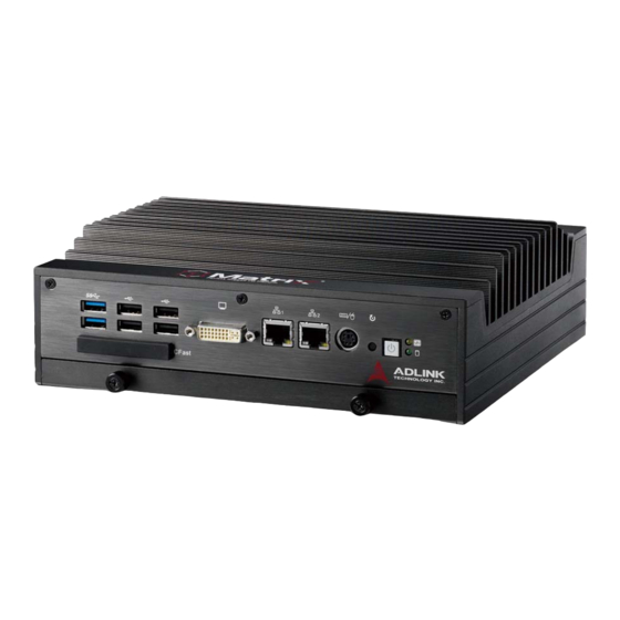
MXE-5300 System Description This section describes the appearance and connectors of the MXE-5300 series, including chassis dimensions, front panel con- nectors, rear panel connectors, and internal IO connectors. 2.1 Mechanical Views (All dimensions are in mm) NOTE: NOTE: Figure 2-1: Front View... - Page 18 Figure 2-3: Top View Figure 2-4: Side View System Description...
-
Page 19: Front Panel I/O Connectors
MXE-5300 2.2 Front Panel I/O Connectors This section describes the functions of the MXE-5300 I/O connec- tors LED Indicators Power Button Reset Button PS/2 keyboard & mouse Dual Gigabit Ethernet ports DVI-I connector USB 2.0 connector x4 (Type A) USB 3.0 connector x2 (Type A) CFast connector(Push-Push,Type II) Table 2-1: MXE-5300 Front Panel Connectors System Description... -
Page 20: Led Indicators
2.2.1 LED Indicators In addition to the LED of the power switch, two LEDs on the front panel indicate the following. LED indicator Color Description If lit continuously, indicates no physical storage is connected Diagnostic Yellow If blinking, indicates no mem- ory is installed on either SO- DIMM socket When blinking, indicates the SATA hard... -
Page 21: Dual Gigabit Ethernet Ports
MXE-5300 2.2.5 Dual Gigabit Ethernet Ports The MXE-5300 provides two Gigabit Ethernet ports on the front panel, an Intel® 82574IT Gigabit Ethernet Controller and Intel® 82579LM Gigabit Ethernet PHY, with features as follows. Intel® 82574IT Gigabit Ethernet Intel® 82579LM Gigabit Ethernet Controller Advanced error reporting 802.3x flow control-compliant... -
Page 22: Table 2-4: Active/Link Led
Figure 2-5: Gigabit Ethernet Ports LED Color Status Description Ethernet port is disconnected. Yellow Ethernet port is connected with no activity. Flashing Ethernet port is connected and active. Table 2-4: Active/Link LED LED Color Status Description 10 Mbps Green/ Green 100 Mbps Orange Orange... -
Page 23: Dvi-I Connector
MXE-5300 2.2.6 DVI-I Connector The MXE-5300 provides one DVI-I connector for external monitor, which can separate to VGA and DVI-D (single link) interfaces. Signal Name Signal Name DVI Data 2- Hot plug detect DVI Data 2+ DVI Data 0- DVI Data 0+ CRT DDC clock CRT DDC data DVI DDC clock... -
Page 24: Usb 3.0 Connectors
Boot priority and device can be configured in BIOS. Please refer to Section 6.2.8 USB Configuration for details. 2.2.8 USB 3.0 Connectors The MXE-5300 provides two Type A USB 3.0 ports on the front panel. Based on the TI TUSB7320RKM USB host controller, con- nection to the host system is achieved through a PCIe x1 Gen2 interface, supporting SuperSpeed, Hi-Speed, full-speed, and low- speed transmission for the downstream USB 3.0 ports. -
Page 25: Rear Panel I/O Connectors
MXE-5300 2.3 Rear Panel I/O Connectors DC Power Supply Connector Dual Gigabit Ethernet ports eSATA Connector Audio Jacks DB-62P COM Ports and Digital I/O Connector 2.3.1 DC Power Supply Connector The DC power supply connector of the MXE-5300, on the back panel, consists of V-, chassis ground, and V+ pins, from right to left. -
Page 26: Dual Gigabit Ethernet Ports
2.3.2 Dual Gigabit Ethernet Ports The back panel provides two Gigabit Ethernet ports, both on RealTek RTL8111C-VC-GR Gigabit Ethernet Controllers. The RTL8111C-VC-GR supports: Integrated 10/100/1000 transceiver Auto-Negotiation with Next Page capability Supports pair swap/polarity/skew correction Crossover detection & Auto-Correction Wake-on-LAN and remote wake-up support Microsoft®... -
Page 27: Esata Connector
MXE-5300 LED Color Status Description Yellow Ethernet port is disconnected. Ethernet port is connected and no data transmission. Flashing Ethernet port is connected and transmitting/ receiving data. Table 2-7: Active/Link LED LED Color Status Description Green/ 10 Mbps Orange Green 100 Mbps Orange 1000 Mbps... -
Page 28: Db-62P Com Port And Digital I/O Connector
2.3.5 DB-62P COM Port and Digital I/O Connector The MXE-5300 features 4 COM ports and 4-CH isolated digital input and 4channel isolated digital output through a DB-62P con- nector on the back panel. Also provided is a cable connect to DB- 62P connector to extend four D-SUB 9-pin connectors and one 25-pin digital I/O connector. -
Page 29: Table 2-9: Db-62P Connector Pin Assignment
MXE-5300 Pin Signal Name Pin Signal Name Pin Signal Name EOGND IDO_3 EOGND EOGND IDO_2 EOGND EOGND IDO_1 EOGND EOGND IDO_0 EOGND IDI_3L IDI_3H +V5DIO_CN_ISO IDI_2L IDI_2H +VDD IDI_1L IDI_1H +VDD IDI_0L IDI_0H Table 2-9: DB-62P Connector Pin Assignment Signal Name RS-232 RS-422 RS-485... -
Page 30: Table 2-11: Digital I/O Specifications
The onboard digital I/O card supports the following specs: 4-CH Isolated DI 4-CH Isolated DO Output Type: Open Drain N- Logic high: 5 to 24 V Channel Power MOSFET driver 250 mA for all channels @60℃, Logic low: 0 to 1.5 V 100% duty Input resistance: 2.4 k @ 0.5 W Supply voltage: 5 to 35 VDC... -
Page 31: Internal I/O Connectors
MXE-5300 2.4 Internal I/O Connectors Figure 2-6: Mainboard Top View (showing Clear CMOS and ME RTC Register Jumpers) 2.4.1 Clear CMOS and ME RTC Register Jumpers Under abnormal conditions in which the MXE-5300 controller fails to boot, clearing the BIOS content stored in CMOS and restoring the default settings may be effective. -
Page 32: Table 2-13: Clear Cmos Jumper
Pin#1 and Pin#2 of JP1 and remove the jumper, after which the CMOS will be restored to factory default settings. Normal Clear Table 2-13: Clear CMOS Jumper As with JP1, shorting Pin#1 and #2 of JP2 will clear the ME RTC register, however, since this jumper is used by RMA, user clearance of the ME RTC register may cause unexpected CAUTION:... -
Page 33: Mini-Pcie Connector
MXE-5300 Figure 2-7: Mainboard Underside View Mini-PCIe Connectors (Default: Rev.1.2, Option: Rev.1.1) DC 5V and 3.3V Connectors for GPS Module USIM Port SATA Connectors 2.4.2 Mini-PCIe Connector Mini-PCIe connectors provide function expansion by enabling installation of a third party Mini-PCIe module such as a WiFi mod- ule, 3.5G module, or other. -
Page 34: Dc 5V And 3.3V Connectors For Gps Module
2.4.3 DC 5V and 3.3V Connectors for GPS Module Two power connectors are provided for GPS module use, one 5V and the other 3.3V, with maximum current rating of each 1A. 2.4.4 USIM Port Use of a 3.5G mini-PCIe module normally requires a SIM card to support communication with a telecom operator. -
Page 35: Getting Started
MXE-5300 Getting Started This chapter discusses installation of hard disk drive, memory, and CFast card. In addition to connection and use of DIO and COM ports, wall-mount installation is also described. 3.1 Installing a Hard Disk Drive Before installing a hard disk drive, remove the bottom cover of the chassis as follows. - Page 36 3. Remove the mounting screw from the top of the HDD bracket. Getting Started...
- Page 37 MXE-5300 4. Pull and lift the HDD bracket. 5. Use the 4 included M3-F head screws to fix one 2.5” HDD or SSD to the bracket. Getting Started...
- Page 38 6. Install the 2.5’’ HDD or SSD to the SATA connector. 7. Reassemble the chassis. Getting Started...
-
Page 39: Installing Memory
MXE-5300 3.2 Installing Memory Before installing RAM, the bottom cover must be removed, as described in steps 1 and 2 of Section 3.1. 1. Remove 3 M3-P head screws from the top of the RAM bracket. 2. Remove 2 M3-F head screws from the front panel. Getting Started... - Page 40 3. Pull and lift the RAM bracket. 4. Insert DDRIII SODIMM RAM into the slot at an angle. Getting Started...
- Page 41 MXE-5300 5. Depress RAM until the latch catches and RAM is securely fixed. Getting Started...
-
Page 42: Installing Cfast Cards
3.3 Installing CFast Cards The MXE-5300 series provides an external CFast socket to accommodate one CFast card, acting as a replacement of the hard disk drive. 1. Remove and rotate the CFast cover to expose the slot 2. Gently insert the CFast card into the CFast socket. - Page 43 MXE-5300 3. Rotate the CFast cover to its orginal position and replace. Getting Started...
-
Page 44: Com Ports And Dio Device
3.4 COM Ports and DIO Device The MXE-5300 series controller integrates 4 COM ports and 4 dig- ital input and 4 digital output ports into a connector, The included breakout cable can connect COM ports and the DIO device. 1. Connect the cable to the connector on the rear panel... - Page 45 MXE-5300 2. The 4 COM ports cables are numbered 1 to 4, with 1 and 2 connecting to RS-232 interface devices and 3 and 4 to RS-422 or RS-485 interface devices. 3. The DIO cable connects to a terminal board for digital input and output.
-
Page 46: Connecting To Dc Power
3.5 Connecting to DC power Before introducing DC power to the MXE-5300 controller, ensure the voltage and polarity provided are compatible with the DC input. Improper input voltage and/or polarity can be responsible for system damage The DC power input connector of the MXE-5300 utilizes V+, V-, and chassis ground pins, and accepts input voltage as shown pre- viously. -
Page 47: Wall-Mounting The Mxe-5300
MXE-5300 3.6 Wall-mounting the MXE-5300 The MXE-5300 controller is shipped with wall-mount brackets and accessory screws, with mounting procedures as follows. 1. Prepare the two wall-mount brackets and 4 M4-P head screws included in the package. Getting Started... - Page 48 2. Remove the 4 plastic pads from the corners of the chas- sis underside. 3. With the 4 included M4-P head screws, fix the 2 wall- mount brackets, also included, to the chassis, according to the spacing dimensions of the screw holes and brack- ets, as shown.
- Page 49 MXE-5300 Getting Started...
-
Page 50: Thermal Considerations
4. Once final assembly as shown is complete, mount the MXE-5300 series controller on the wall via the screw holes. 3.7 Thermal Considerations Heat-generating components of the MXE-5300 (such as CPU and PCH) are all situated on the left side of the system. These compo- nents directly contact the heat sink via thermal pads and dissipate heat generated by the components. -
Page 51: Driver Installation
MXE-5300 Driver Installation This section describes the drivers needed for Windows operating systems and the procedures to install them. For other OS support, please contact ADLINK for further information. Properly install Windows before installing any drivers. Most stan- dard I/O device drivers have been included in Windows. The fol- lowing drivers must be installed: Chipset Graphics... -
Page 52: Installing The Graphics Driver
tion\Matrix\MXE-5300\Chipset\ (where x: denotes the DVD-ROM drive) 3. Execute Setup.exe and follow the onscreen instructions to complete the setup. 4. After installation is complete, reboot the system. 4.2 Installing the Graphics Driver The MXE-5300 is equipped with the Intel® HD Graphic 3000 graphics media accelerator integrated in Intel Mobile Intel®... -
Page 53: Installing The Audio Driver
MXE-5300 To install the driver for Intel 82547 Gigabit Ethernet controller, for Windows 7 and XP users: 1. Close any running applications. 2. Insert the ADLINK All-in-One DVD; the Ethernet driver is located in the directory: x:\Driver Installa- tion\Matrix\MXE-5300\LAN-Intel\ (where x: denotes the DVD-ROM drive). - Page 54 tion\Matrix\MXE-5300\WDT\ (where x: denotes the DVD- ROM drive). 3. Execute Setup.exe and follow the onscreen instructions to complete the setup. 4. After installation is complete, reboot the system. Driver Installation...
-
Page 55: Bios Settings
MXE-5300 BIOS Settings The Basic Input/Output System (BIOS) is a program that provides a basic level of communication between the processor and periph- erals. In addition, the BIOS also contains codes for various advanced features applied to the MXE-5300. The BIOS setup pro- gram includes menus for configuring settings and enabling fea- tures of MXE-5300. -
Page 56: Main
5.1 Main 5.1.1 BIOS Information Shows current system BIOS code version and BIOS version. 5.1.2 System Time/System Date Use this option to change the system time and date. Highlight Sys- tem Time or System Date using the up or down <Arrow> keys. Enter new values using the keyboard then <Enter>. -
Page 57: Advanced
MXE-5300 5.2 Advanced Setting incorrect or conflicting values in Advanced BIOS Setup may cause system malfunctions. CAUTION: BIOS Settings... -
Page 58: Acpi Settings
5.2.1 ACPI Settings Enable ACPI Auto Configuration Enables or disables BIOS ACPI Auto Configuration. Enable Hibernation Enables or disables system's ability to hibernate. This option may be not effective with some OS. ACPI Sleep State Selects the highest ACPI sleep state the system will enter when the SUSPEND button is pressed. -
Page 59: Cpu Configuration
MXE-5300 5.2.2 CPU Configuration Limit CPUID Maximum Disabled for Windows XP. Execute Disable Bit Enables XD to prevent certain classes of malicious buffer over- flow attacks when combined with a supporting OS. Hardware Prefetcher Enables or disables the Mid Level Cache (L2) streamer prefetcher. - Page 60 Intel Virtualization Technology When enabled, a VMM can utilize the additional hardware capabilities provided by Vanderpool Technology. Local x2APIC Enables Local x2APIC, some OS do not support this. EIST Enables/disables Intel SpeedStep Technology. Turbo Mode Enables/disables Intel TurboBoost Technology. C1E Function When enabled, lets CPU enter enhanced C1 sleep state to save more power than C1.
-
Page 61: Onboard Device Configuration
MXE-5300 5.2.3 Onboard Device Configuration Intel 82579LM LAN Enables/disables onboard Intel 82579LM (built-in PCH) LAN controller. Launch Intel 82579LM LAN PXE OpROM Enables or disables execution of LAN boot-rom to add boot option for legacy network devices. Intel 82574 LAN Enables/disables onboard Intel 82574 LAN controller. -
Page 62: Advanced Power Management
Launch RealTek 8111C PXE OpROM Enables or disables execution of LAN boot-rom to add boot option for legacy network devices. RealTek 8111C LAN #2 (Appear on MXE5300 only) Enables/disables onboard RealTek 8111C LAN controller. Launch RealTek 8111C PXE OpROM Enables or disables execution of LAN boot-rom to add boot option for legacy network devices. -
Page 63: Table 5-1: Restore On Power Loss
MXE-5300 Restore On AC Power Loss Determines the state the computer enters when power is restored after a power loss. Options for this value are Last State, Power On and Power Off. Option Description When set, powers the system down when Power Off power is restored. -
Page 64: Sata Configuration
5.2.5 SATA Configuration SATA Controller(s) Enables/disables internal serial ATA controller SATA Mode Selection This option selects the SATA channel configuration from among (1) IDE Mode or (2) AHCI Mode Serial ATA Port 0 / C-Fast Port / E-SATA Port Port X Enables or disables SATA Port X Hot Plug Sets this port as hot pluggable. -
Page 65: Intel Anti-Theft Technology Configuration
MXE-5300 5.2.6 Intel Anti-Theft Technology Configuration 5.2.7 Intel Anti-Theft Technology ® Enables or disables Intel AT function. Intel Anti-Theft Technology helps stop theft by making computers non-functional with immedi- ate shutdown. Intel Anti-Theft Technology Recovery/Enter Intel AT suspend mode Miscellaneous settings for Intel AT function. BIOS Settings... -
Page 66: Amt Configuration
5.2.8 AMT Configuration Intel AMT Enables/disables Intel AMT function. Intel AMT Setup Prompt Enables/disables launching of MEBx during system post for configuring AMT features. BIOS Hotkey Pressed/MEBx Selection Screen Miscellaneous settings for iAMT function. BIOS Settings... -
Page 67: Usb Configuration
MXE-5300 5.2.9 USB Configuration Legacy USB Support AUTO option disables legacy support if no USB devices are connected, DISABLE option keeps USB devices available only for EFI applications. USB3.0 Support Enables or disables USB3.0 (XHCI) controller support, allowing USB 3.0 devices to be used in DOS environment. XHCI Hand-Off Enables BIOS support of XHCI Hand-Off feature. -
Page 68: 10Super Io Configuration
5.2.10 Super IO Configuration Serial Port 1 to 4 Configuration Can enable/disable the port, select port type (RS-232/422/485) for Serial Port 1 and 2 only, or change the port settings (address). BIOS Settings... -
Page 69: W Monitor
MXE-5300 5.2.11 H/W Monitor PC Health Status The hardware health on Super I/O supports Board Tempera- ture 1/2, CPU Temperature, CPU Voltage, I-GFX Voltage, VCCSA Voltage, +1.05V, +3.3V, +1.5V, +5V, +12.0V, and VBAT. BIOS Settings... -
Page 70: 12Serial Port Console Redirection
5.2.12 Serial Port Console Redirection COM 1 to 4, SOL (Serial Over LAN) COM Console Redirection Enables console redirection of COM 1 to 4, SOL COM. Console Redirection Settings Miscellaneous parameters for COM Port 1 to 4, SOL COM. Serial Port for Out-of-Band Management/EMS Console Redirection Enables console redirection for remote management of a Windows Server OS through the port selected by Out-... -
Page 71: Chipset
MXE-5300 Out-of-Band Mgmt Port Selects the COM Port for remote management of a Win- dows OS. Terminal Type Selects the transmission protocol for remote terminal console. 5.3 Chipset BIOS Settings... -
Page 72: System Agent (Sa) Configuration
5.3.1 System Agent (SA) Configuration VT-d Enables VT-d function for efficient virtualization of I/O devices. Graphics Configuration Selects internal graphic device shared memory size and power policy. BIOS Settings... - Page 73 MXE-5300 Graphics Turbo IMON Current Sets the maximum IMON current value for graphics turbo mode. GTT Size Selects GTT size for internal graphics. DVMT Pre-Allocated Selects DVMT 5.0 pre-allocated graphics memory size used by the internal graphics device. DVMT Total Gfx Memory Selects DVMT 5.0 total graphics memory size used by the internal graphics device.
-
Page 74: Boot
5.4 Boot 5.4.1 Boot Configuration Setup Prompt Timeout Number of seconds to wait for setup activation key (DEL). Bootup Num-Lock State Allows Number Lock setting to be modified during boot. Quiet Boot When Disabled, directs BIOS to display POST messages; when Enabled, directs BIOS to display the OEM logo. -
Page 75: Boot Option Priorities
MXE-5300 5.4.2 Boot Option Priorities Specifies the priority of boot devices, with all installed boot devices detected during POST and displayed, selecting Boot Option # specifies the desired boot device. 5.5 Security If only the Administrator’s password is set, only access to Setup is limited and is only requested when entering Setup. -
Page 76: Exit
User Password Sets boot/setup User password 5.6 Exit Save Changes and Exit When BIOS settings are complete, selecting this option saves all changes and reboots the system, and new settings take effect. Discard Changes and Exit Discards all changes and exits BIOS setup. Discard Changes and Reset Resets system setup without saving any changes. - Page 77 MXE-5300 Restore Defaults Returns all BIOS options to Default settings, designed for max- imum system stability, but not performance. Applicable in the event of system configuration problems. Launch EFI Shell from filesystem device Attempts to launch EFI Shell application (Shellx64.efi) from one of the available filesystem devices.
- Page 78 This page intentionally left blank. BIOS Settings...
-
Page 79: A Appendix: Wdt Function Reference
MXE-5300 Appendix A WDT Function Reference A.1 Watchdog Timer (WDT) Function Reference This appendix describes the usage of the watchdog timer (WDT) function library for the MXE-5300 controller. Watchdog timer is a hardware mechanism to reset the system in case the operating system or an application halts. - Page 80 MXE-5300 SetWDT Description Set the timeout value of watchdog timer. There are two param- eters for this function to indicate the timeout ticks and unit. Users should call ResetWDT or StopWDT before the expiration of watchdog timer, or the system will be reset. Supported controllers MXE-5300 Syntax...
- Page 81 MXE-5300 StartWDT Description Start the watchdog timer function. Once the StartWDT is invoked, the countdown of watchdog timer starts. Users should call ResetWDT or StopWDT before the expiration of watchdog timer, or the system will be reset. Supported controllers MXE-5300 Syntax C/C++ BOOL StartWDT()
- Page 82 MXE-5300 Return codes TRUE if watchdog timer is successfully reset. FALSE if watchdog timer is failed to reset. StopWDT Description Stop the watchdog timer. Supported controllers MXE-5300 Syntax C/C++ BOOL StopWDT() Parameters None Return codes TRUE if watchdog timer is successfully stopped. FALSE if watchdog timer is failed to stop.
-
Page 83: Important Safety Instructions
PXIe-3975 Important Safety Instructions For user safety, please read and follow all instructions, WARNINGS, CAUTIONS, and NOTES marked in this manual and on the associated equipment before handling/operating the equipment. Read these safety instructions carefully. Keep this user’s manual for future reference. Read the specifications section of this manual for detailed information on the operating environment of this equipment. - Page 84 Never attempt to fix the equipment. Equipment should only be serviced by qualified personnel. A Lithium-type battery may be provided for uninterrupted, backup or emergency power. Risk of explosion if battery is replaced with an incorrect type; please dispose of used batteries appropriately. Equipment must be serviced by authorized technicians when: The power cord or plug is damaged;...
-
Page 85: Getting Service
5215 Hellyer Avenue, #110, San Jose, CA 95138, USA Tel: +1-408-360-0200 Toll Free: +1-800-966-5200 (USA only) Fax: +1-408-360-0222 Email: info@adlinktech.com ADLINK Technology (China) Co., Ltd. Address: (201203) 300 Fang Chun Rd., Zhangjiang Hi-Tech Park, Pudong New Area, Shanghai, 201203 China Tel: +86-21-5132-8988 Fax:... - Page 86 84 Genting Lane #07-02A, Cityneon Design Centre, Singapore 349584 Tel: +65-6844-2261 Fax: +65-6844-2263 Email: singapore@adlinktech.com ADLINK Technology Singapore Pte. Ltd. (Indian Liaison Office) Address: 1st Floor, #50-56 (Between 16th/17th Cross) Margosa Plaza, Margosa Main Road, Malleswaram, Bangalore-560055, India Tel: +91-80-65605817, +91-80-42246107 Fax: +91-80-23464606 Email: india@adlinktech.com...
Need help?
Do you have a question about the MXE-5300 Series and is the answer not in the manual?
Questions and answers