Table of Contents

Related Manuals for ADLINK Technology MXC-2300


Summary of Contents for ADLINK Technology MXC-2300
- Page 1 MXC-2300 ® ™ Intel Atom E3845 Quad-Core Processor-based Fanless Expandable Embedded Computer with PCI/PCIe Slots PRELIMINARY Manual Rev.: April 18, 2013 Revision Date: 50-PRE Part No: Advance Technologies; Automate the World.
- Page 2 Revision History Revision Release Date Description of Change(s) PRELIMINARY April 18, 2013 Pre-Initial Release Please note that this is a PRELIMINARY version of the User’s Manual. While every effort has been made to ensure the contents hereof are currently accurate, sub- NOTE: NOTE: sequent releases may contain changes to the specifica-...
-
Page 3: Preface
MXC-2300 Preface Copyright 2014 ADLINK Technology, Inc. This document contains proprietary information protected by copy- right. All rights are reserved. No part of this manual may be repro- duced by any mechanical, electronic, or other means in any form without prior written permission of the manufacturer. - Page 4 Conventions Take note of the following conventions used throughout this manual to make sure that users perform certain tasks and instructions properly. Additional information, aids, and tips that help users perform tasks. NOTE: NOTE: Information to prevent minor physical injury, component dam- age, data loss, and/or program corruption when trying to com- plete a task.
-
Page 5: Table Of Contents
MXC-2300 Table of Contents Revision History..............ii Preface ..................iii List of Tables................ix List of Figures ................ xi 1 Introduction ................ 1 Overview................1 Features................2 Specifications............... 3 Schematics and Dimensions ..........7 Front Panel I/O Connectors ..........11 1.5.1... - Page 6 Installing a PCI/PCIe Card ..........39 Installing a mini-PCI-E device ..........41 Installing CF Cards ............44 Connecting DC Power ............47 Wall-mounting the MXC-2300..........47 Optional Fan Module............51 Cooling Considerations............52 3 Driver Installation.............. 53 Installing the Chipset Driver ..........54 Installing the Graphics Driver..........
- Page 7 MXC-2300 Installing the WDT Driver/API ..........56 Installing the DI/O Driver/API..........57 A Appendix: Power Supply & Consumption ...... 59 Power Consumption Reference......... 59 Power Supply Reference ........... 60 Accessory Cabling ............. 60 Important Safety Instructions ..........61 Getting Service..............63...
- Page 8 This page intentionally left blank. viii Table of Contents...
-
Page 9: List Of Tables
MXC-2300 List of Tables Table 1-1: Front Panel I/O Connector Legend......12 Table 1-2: LED Indicators ............13 Table 1-3: Digital I/O Connector Pin Signals ......15 Table 1-4: Digital I/O Connector Pin Legend ......16 Table 1-5: CAN Port Pin Assignments........20 Table 1-6: Active/Link LED ............ - Page 10 This page intentionally left blank. List of Tables...
-
Page 11: List Of Figures
MXC-2300 List of Figures Figure 1-1: MXC-2300 Functional Block Diagram ......6 Figure 1-2: MXC-2300 Left Side View .......... 7 Figure 1-3: MXC-2300 Front View ..........8 Figure 1-4: MXC-2300 Top View ..........9 Figure 1-5: MXC-2300 Rear View..........9 Figure 1-6: MXC-2300 Underside View ........ - Page 12 This page intentionally left blank. List of Figures...
-
Page 13: Introduction
® Featuring the latest Intel Atom™ E3845 Quad-core processor, the Matrix MXC-2300 series excels with minimal power consump- tion, exceptional 3D graphics, and powerful media acceleration, delivering leading improvements in performance and cost-effi- ciency over any previous generation Atom-based system. -
Page 14: Features
1.2 Features Intel® Atom™ E3845 processor with 4C @1.91 GHz SoC 2x DDR3L SO-DIMM, supporting up to 8GB memory 2 PCI + 1 PCIe x4 or 3 PCI expansion slots Built-in dual-port isolated CAN and 16-CH isolated DI and 1 DisplayPort + 1 DVI-I 2 Intel GbE ports with teaming function, 1 USB 3.0 + 4 USB 2.0 ports 1 external CF slot and 1 internal PCIe Mini Card socket with... -
Page 15: Specifications
MXC-2300 1.3 Specifications MXC- MXC- MXC- MXC- 2300CD-3E1 2300CD-3S 2300-3E1 2300-3S System Core ® ™ Intel Atom Processor E3845 (Bay Trail-I Processor Premium) 4C @ 1.91GHz CPU Chipset Intel SoC (System on Chip) 1 DisplayPort +1 DVI-I (VGA or DVI-D) - Page 16 MXC- MXC- MXC- MXC- 2300CD-3E1 2300CD-3S 2300-3E1 2300-3S Power Supply Built-in 9-32 V wide-range DC input pluggable DC Input connectors with latch (GND, V-, V+), 2-pin remote power on/off switch AC Input Optional 100 W external AC-DC adapter for AC input Storage SATA HDD Onboard SATA-II port for 2.5”...
- Page 17 Power Recommended System System Full Supply Power Off* Power Idle** Load*** (24VDC) Supply**** Integrated Embedded Computer MXC-2300 i7 2.16 W 18.48 W 91.2 W 160W MXC-2300 i5 2.16 W 16.8 W 67.2 W 160W MXC-2300 i3 2.16 W 16.08 W 53.76 W...
-
Page 18: Figure 1-1: Mxc-2300 Functional Block Diagram
PCIe x1 RJ45 & Intel WGI210IT USB2.0 x 2 USB 2.0 SATA II Connector SATA Connector Line out & Audio Mic in SMBus Connector SEMA BMC COM x4 Super I/O Dsub -9 ITE IT8786F Figure 1-1: MXC-2300 Functional Block Diagram Introduction... -
Page 19: Schematics And Dimensions
MXC-2300 1.4 Schematics and Dimensions All dimensions shown are in mm (millimeters). NOTE: NOTE: 219.1 Figure 1-2: MXC-2300 Left Side View Introduction... -
Page 20: Figure 1-3: Mxc-2300 Front View
141.6 Figure 1-3: MXC-2300 Front View Introduction... -
Page 21: Figure 1-4: Mxc-2300 Top View
MXC-2300 Figure 1-4: MXC-2300 Top View Figure 1-5: MXC-2300 Rear View Introduction... -
Page 22: Figure 1-6: Mxc-2300 Underside View
98.3 67.3 179.1 Figure 1-6: MXC-2300 Underside View Introduction... -
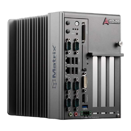
Page 23: Front Panel I/O Connectors
MXC-2300 1.5 Front Panel I/O Connectors Figure 1-7: Front Panel I/O Connectors Power Button Digital I/O connector Introduction... -
Page 24: Power Button
DC power supply connector COM port x4 5V 32-Bit PCI slot x 2 PCIExpressx4slot(MXC-2300-3E1) Audio Jacks 5V 32-Bit PCI slot (MXC-2300-3S) Table 1-1: Front Panel I/O Connector Legend 1.5.1 Power Button The power button is a non-latched push button with a blue LED indicator. -
Page 25: Led Indicators
Table 1-2: LED Indicators 1.5.3 Reset Button The reset button executes a hard reset for the MXC-2300. 1.6 Digital I/O Connector The MXC-2300 controller features an onboard isolated digital I/O circuit with a 68-pin VHDCI (Very High Density Cable Intercon- nect) connector on the front panel. -
Page 26: Isolated 5V Dc Power Source For Do
Sink current up to 100 mA (sustained loading) or 250 mA (peak loading) on each isolated output channel Supply voltage: 5 to 35 V DC Isolation type: Digital Isolator Isolation voltage: 1500 V DC Flywheel diode for VDD on all DO channels Isolated 5V DC Power Source for DO Supply voltage: 5 ±... -
Page 27: Table 1-3: Digital I/O Connector Pin Signals
MXC-2300 Pin Signal Pin Signal Pin Signal +VDD DI1_L EOGND EOGND 25 DI0_H DO10 DI0_L EOGND EOGND 27 DI11 ISO_COM EOGND EOGND 29 DI10 ISO_COM DI7_H EOGND 31 DI7_L ISO_COM DI6_H EOGND 33 DI6_L ISO_COM DI5_H EOGND 35 +VDD DI5_L... -
Page 28: Isolated Digital Input Circuits
High input of isolated differential DI channel DIn_H (n=0 to 7) Low input of isolated differential DI channel DIn_L (n=0 to 7) Input of isolated DI channel (n=8 to 15) Common ground of isolated DI channel ISO_COM 8 to 15 Output of isolated DO channel (n=0 to 15) Ground return path of isolated DO channel... -
Page 29: Figure 1-8: Isolated Digital Input Circuit
MXC-2300 Figure 1-8: Isolated Digital Input Circuit Photocoupler 8.2k DI_n ISO_COM Figure 1-9: Isolated Digital Input Differential Input Circuit Introduction... -
Page 30: Figure 1-10: Isolated Digital Input Sample Application Circuit
Power Photocoupler 8.2 k DI_n ISO_COM Power Photocoupler 8.2 k DI_n ISO_COM Figure 1-10: Isolated Digital Input Sample Application Circuit Introduction... -
Page 31: Isolated Digital Output Circuits
Figure 1-12: Isolated Digital Output Sample Application Circuit 1.6.3 Digital I/O Windows Driver and API The MXC-2300 DI/O incorporates ADLINK’s PCMe-1432 Win- dows driver, on the bundled driver CD or downloadable from Adlink's MXC-2300 web support page (driver for MXC-2300 DI/O). Introduction... -
Page 32: Controller Area Network (Can) Port
1.6.4 Controller Area Network (CAN) Port Figure 1-13: CAN Port Signal Signal CAN_L CAN_H Table 1-5: CAN Port Pin Assignments The Controller Area Network (CAN) interface supports dual-port isolated CAN connection that can run independently or bridged at the same time. The built-in CAN controller is a Phillips SJA1000, providing bus arbitration and error detection with auto correction and re-transmission capability, and features: Dual independent CAN network operation... -
Page 33: Usb 2.0 Ports
BIOS. Please refer to Section B.8: Security on page 88 for details. 1.6.6 USB 3.0 Ports The MXC-2300 provides a USB 3.0 port supporting Type A USB 3.0 connection on the front panel, compatible with super-speed, high-speed, full-speed and low-speed USB devices. -
Page 34: Compact Flash Socket
The CF interface is transferred from SATA by an ASIC, and can be an alternative storage device for system installation. The MXC-2300 can boot via a CF card with OS installed. Due to the nature of the SATA interface, the CF card cannot hot-plug and must be installed before powering up the system. -
Page 35: Dvi-I Connector
MXC-2300 1.6.9 DVI-I Connector The MXC-2300 provides one DVI-I connector providing connec- tion to an external monitor. Since VGA signals are analog based, VGA display quality is greatly affected by quality and length of cable used. We strongly recommended VGA cable less than 2 meters in length CAUTION: with effective shielding, such as UL style 2919 AWM. -
Page 36: Com Port Connectors
1.6.10 COM Port Connectors The MXC-2300 provides four COM ports through D-sub 9 pin con- nectors. The COM1 & COM2 ports support RS-232/422/485 modes by BIOS setting, while COM3 and COM4 support only RS- 232. Signal Name RS-232 RS-422 RS-485... -
Page 37: Audio Jacks
30-01157-0000 Active DisplayPort to DVI adapter cable Table 1-11: Applicable Cable Types 1.6.12 Audio Jacks The MXC-2300 implements Intel High Definition audio on a Realtek ALC269 chip. The HD audio supports up to 24-bit, 192 KHz sample rate high quality headphone/line out and microphone Introduction... -
Page 38: Dc Power Connector
Table 1-12: Audio Jack Signals 1.6.13 DC Power Connector The DC power supply connector of the MXC-2300 is on the front panel. The power supply connector consists of three pins, V+, chassis ground, and V- from right to left respectively. V+ and V- pins provide DC power input and the chassis ground pin allows connection of the chassis to ground for better EMC compatibility. -
Page 39: Pci Slot
Table 1-13: DC Power Supply Connector Signals 1.6.14 PCI Slot The MXC-2300 provides two PCI slots, based on the PCIe to PCI bridge, with connection to the host system achieved through a PCIe interface, supporting universal or 5V PCI 32-bit cards operat- ing at 33/66MHz clocks. -
Page 40: Internal I/O Connectors
1.7 Internal I/O connectors Figure 1-15: Mainboard PCB Clear CMOS jumper CMOS RTC Battery Reserved +5V and +12V connector Extra +5V voltage connector Extra +3.3V voltage connector Introduction... -
Page 41: Table 1-14: Mainboard Connector Legend
MXC-2300 12V DC fan connector Mini PCI Express slot & USIM socket 2nd DDR3L DIMM socket Table 1-14: Mainboard Connector Legend Figure 1-16: Backplane Board PCB 5V 32Bit PCI slot 5V 32Bit PCI slot PCI Express x4 slot Internal USB dongle connector... -
Page 42: Clear Cmos Jumper
Table 1-16: Clear CMOS Jumper Settings 1.7.2 Internal Reserved +5V and +12V Connector The MXC-2300 provides one power pin header with +5V and +12V DC power, providing access for PCI and PCI express card external power supplies. Please refer to Section A.2:Power Supply Reference for +5V and... -
Page 43: Dc Fan Connector
Table 1-17: +5V and +12V Connector Pin Functions 1.7.3 12V DC Fan Connector The MXC-2300 provides a DC 12V to USB connector for fan mod- ule power. The optional fan module connects to the connector when assembled to the chassis. -
Page 44: Backboard To System Pcb Connector
1.7.6 Backboard to System PCB Connector This connector connects the backboard to a golden finger- equipped mainboard PCB. Introduction... -
Page 45: Getting Started
Retain the shipping carton and packing materials for inspection. Obtain authorization from your dealer before returning any product to ADLINK. Ensure that the fol- lowing items are included in the package. MXC-2300 controller Accessory box Screw pack for wall-mounting and HDD fixing Quick Start Guide... -
Page 46: Installing Hard Disk Drives
2.2 Installing Hard Disk Drives Before installing hard disk drives, remove the cover from the chas- sis as follows. 1. Loosen the thumbscrew on the front panel by hand or screwdriver. Getting Started... - Page 47 MXC-2300 2. Withdraw the thumbscrew and remove the top cover by lifting. Getting Started...
- Page 48 3. Remove 2 screws from the back cover. 4. Place the chassis upside down and remove the other 2 screws from the bottom of the back cover. Getting Started...
- Page 49 MXC-2300 5. Lift and pull the back cover. Getting Started...
- Page 50 6. Use the 4 M3 screws included in the package to fix a 2.5” HDD or SSD unit to the bracket. 7. Gently reinstall the cover and depress the HDD/SSD bracket to the SATA connector on the PCB. 8. Reverse Steps 3 and 4 to fasten the 4 screws. 9.
-
Page 51: Installing A Pci/Pcie Card
MXC-2300 2.3 Installing a PCI/PCIe Card Follow steps 1-2 in Section 2.2:Installing Hard Disk Drives to remove the top cover before installing a PCI/PCIe card. 1. Insert thePCI/PCIe card into the PCI/PCIe slot. Ensure that the lower edge of the PCI/PCIe card aligns with the alignment guide. - Page 52 2. Adjust the position of the included card brace to firmly fix the card. Tighten the screw to fix the brace. 3. Replace the top cover and fasten the thumbscrew. Getting Started...
-
Page 53: Installing A Mini-Pci-E Device
MXC-2300 2.4 Installing a mini-PCI-E device According to steps 1-2 in Section 2.2, remove the top cover. 1. Remove 4 screws from the right side cover. 2. Remove the single screw from the back cover. Getting Started... - Page 54 3. Place the chassis left side down and lift the left side cover. 4. Insert the mini-PCI-E wireless module into the slot at an angle. Getting Started...
- Page 55 MXC-2300 5. Press the mini-PCI-E wireless module until seated and fix with the 2 M2.5-P-head-L5 screws. 6. Reverse Steps 1 to 3 to reinstall the left side cover and fasten the 5 screws, then replace the top cover and fas- ten the thumbscrew.
-
Page 56: Installing Cf Cards
2.5 Installing CF Cards The MXC-2300 series controller provides an external CF socket to accommodate a CF card. Remove the top cover according to steps 1-2 in Section 2.2. 1. Remove the external CF socket cover. Getting Started... - Page 57 MXC-2300 2. Align the CFast card with the guide of the CFast socket. Getting Started...
- Page 58 3. Gently insert the CFast card until it is firmly seated in the socket, as shown. Getting Started...
-
Page 59: Connecting Dc Power
WARNING: The DC power input connector of the MXC-2300 has V+, V- , and chassis ground pins, and accepts input voltage as shown previ- ously. Connect DC power as shown. Two screws fasten to secure the plug. - Page 60 Wall–mounting procedures follow. 1. Remove the 4 plastic pads from the corners. 2. Use the 4 M4 screws shipped with the controller to fix the 2 wall-mount brackets, also included, to the chassis, according to the spacing dimensions of the screw holes and brackets, as shown.
- Page 61 MXC-2300 229.1 243.1 Getting Started...
- Page 62 10.0 3. Once final assembly as shown is complete, mount the MXC-2300 on the wall via screw holes. Getting Started...
-
Page 63: Optional Fan Module
MXC-2300 2.8 Optional Fan Module The MXC-2300 can be optionally equipped with an easily installed fan module providing heat dissipation. To install the fan module: 1. Follow steps 1-2 in Section 2.2 to remove the top cover. Seat the fan module in the chassis. -
Page 64: Cooling Considerations
3. Replace the thumbscrews. 2.9 Cooling Considerations Heat-generating components of the MXC-2300 (such as CPU and PCH) are all situated on the left side of the system. These compo- nents directly contact the heat sink via thermal pads and dissipate heat generated by the components. -
Page 65: Driver Installation
Windows operating systems and the procedures to install them. For other OS support, please contact ADLINK for further information. The MXC-2300 enables full driver support for systems running Windows 8 32 or 64 bit. Ensure the Microsoft Windows OS is fully installed before... -
Page 66: Installing The Chipset Driver
3. Execute Setup.exe and follow onscreen instructions to complete the setup. 4. After installation is complete, reboot the system. 3.2 Installing the Graphics Driver ® The MXC-2300 is equipped with the Intel HD Graphics 4000 ® integrated in the Intel Core i7. -
Page 67: Installing The Ethernet Driver
4. After installation is complete, reboot the system. 3.5 Installing the USB 3.0 Driver The MXC-2300 supports USB 3.0 using Intel Atom E3845 SoC chipset. 1. Close any running applications. 2. Insert the ADLINK All-in-One DVD. The drivers are... -
Page 68: Installing The Intel Management Engine Driver
4. After installation is complete, reboot the system. 3.6 Installing the Intel Management Engine Driver The MXC-2300 supports the Intel Management Engine on the Intel QM77 chipset. 1. Close any running applications. 2. Insert the ADLINK All-in-One DVD. The drivers are... -
Page 69: Installing The Di/O Driver/Api
6. After installation is complete, reboot the system. 3.8 Installing the DI/O Driver/API The MXC-2300 also provides 12 channels for DI and 12 for chan- nels DO based on the PCMe-1432. To install the DI/O driver/API: 1. Close any running applications. - Page 70 This page intentionally left blank. Driver Installation...
-
Page 71: A Appendix: Power Supply & Consumption
MXC-2300 Appendix A Power Supply & Consump- tion Information in this Appendix is for power budget planning and design purposes only. Actual power consumption may differ based on final application. NOTE: NOTE: A.1 Power Consumption Reference Power consumption as follows is based on lab data in which 24V DC is applied and current is measured by the DC power supply. -
Page 72: Power Supply Reference
Sufficient power supply for the entire system is required to meet these specifications. At least 100W at 24V input is recommended. NOTE: NOTE: Heat generated by add-on PCI/PCIe adapters affects thermal stability. Additional heat dissipa- tion is required when the system operates at high temperatures or in harsh environments with add-on adapters. -
Page 73: Important Safety Instructions
MXC-2300 Important Safety Instructions For user safety, please read and follow all instructions, WARNINGS, CAUTIONS, and NOTES marked in this manual and on the associated equipment before handling/operating the equipment. Read these safety instructions carefully. Keep this user’s manual for future reference. - Page 74 Never attempt to fix the equipment. Equipment should only be serviced by qualified personnel. A Lithium-type battery may be provided for uninterrupted, backup or emergency power. There is risk of explosion if the battery is replaced with an incorrect type. Dispose of used batteries appropriately. WARNING: Equipment must be serviced by authorized technicians when:...
-
Page 75: Getting Service
San Jose, CA 95138, USA Tel: +1-408-360-0200 Toll Free: +1-800-966-5200 (USA only) Fax: +1-408-360-0222 Email: info@adlinktech.com ADLINK Technology (China) Co., Ltd. Address: (201203) 300 Fang Chun Rd., Zhangjiang Hi-Tech Park Pudong New Area, Shanghai, 201203 China Tel: +86-21-5132-8988 Fax: +86-21-5132-3588 Email: market@adlinktech.com... - Page 76 84 Genting Lane #07-02A, Cityneon Design Centre Singapore 349584 Tel: +65-6844-2261 Fax: +65-6844-2263 Email: singapore@adlinktech.com ADLINK Technology Singapore Pte. Ltd. (Indian Liaison Office) Address: #50-56, First Floor, Spearhead Towers Margosa Main Road (between 16th/17th Cross) Malleswaram, Bangalore - 560 055, India Tel: +91-80-65605817, +91-80-42246107 Fax:...
Need help?
Do you have a question about the MXC-2300 and is the answer not in the manual?
Questions and answers