Table of Contents
Advertisement
Quick Links
Advertisement
Table of Contents

Related Manuals for Lenovo ThinkSystem SR665


Summary of Contents for Lenovo ThinkSystem SR665
- Page 1 ThinkSystem SR665 Maintenance Manual Machine Types: 7D2V and 7D2W...
- Page 2 Before using this information and the product it supports, be sure to read and understand the safety information and the safety instructions, which are available at: http://thinksystem.lenovofiles.com/help/topic/safety_documentation/pdf_files.html In addition, ensure that you are familiar with the terms and conditions of the Lenovo warranty for your server, which can be found at: http://datacentersupport.lenovo.com/warrantylookup First Edition (June 2020) ©...
-
Page 3: Table Of Contents
+16NVMe) ....backplane ....182 Install the front 2.5-inch-drive backplane . . . 185 © Copyright Lenovo 2019... - Page 4 ....291 Remove the system fan cage ..387 Install the system fan cage ..389 ThinkSystem SR665 Maintenance Manual...
- Page 5 Index ....449 Power problems ... . . 427 Network problems ... . 428 © Copyright Lenovo 2019...
- Page 6 ThinkSystem SR665 Maintenance Manual...
-
Page 7: Safety
Vor der Installation dieses Produkts die Sicherheitshinweise lesen. Prima di installare questo prodotto, leggere le Informazioni sulla Sicurezza. Les sikkerhetsinformasjonen (Safety Information) før du installerer dette produktet. Antes de instalar este produto, leia as Informações sobre Segurança. © Copyright Lenovo 2019... -
Page 8: Safety Inspection Checklist
1 & IEC 60950-1, the standard for Safety of Electronic Equipment within the Field of Audio/Video, Information Technology and Communication Technology. Lenovo assumes you are qualified in the servicing of equipment and trained in recognizing hazards energy levels in products. Access to the equipment is by the use of a tool, lock and key, or other means of security, and is controlled by the authority responsible for the location. - Page 9 Click the Power tab to see all line cords. • Make sure that the insulation is not frayed or worn. 3. Check for any obvious non-Lenovo alterations. Use good judgment as to the safety of any non-Lenovo alterations. 4. Check inside the server for any obvious unsafe conditions, such as metal filings, contamination, water or other liquid, or signs of fire or smoke damage.
- Page 10 ThinkSystem SR665 Maintenance Manual viii...
-
Page 11: Chapter 1. Introduction
Identifying your server When you contact Lenovo for help, the machine type and serial number information helps support technicians to identify your server and provide faster service. The machine type and serial number are on the ID label on the right rack latch in the front of the server. - Page 12 Scan the QR code with a mobile device and a QR code reader application to get quick access to the Lenovo Service Web site for this server. The Lenovo Service Information Web site provides additional information for parts installation and replacement videos, and error codes for server support.
-
Page 13: Specifications
Note: The operating speed and total memory capacity depend on the processor model and UEFI settings. For a list of supported memory, see the Lenovo ServerProven Web site: https://static.lenovo.com/us/en/serverproven/index.shtml For technical rules for memory modules, see “Technical rules for memory modules” on page 135. - Page 14 – One diagnostics panel or LCD diagnostics panel (optional) • Rear: – One VGA connector – Three USB 3.1 Gen 1 connectors – One XClarity Controller network connector – Two or four Ethernet connectors on the OCP 3.0 Ethernet adapter (optional) ThinkSystem SR665 Maintenance Manual...
- Page 15 Table 1. Server specifications (continued) Specification Description Storage controllers Support for JBOD mode and RAID level 0, 1, 10: • 530-16i PCIe 12Gb SFF RAID adapter (Gen3) Support for JBOD mode and RAID level 0, 1, 5, 10, 50: • 530-8i PCIe 12Gb SFF RAID adapter (Gen3) Support for JBOD mode and RAID level 0, 1, 5, 6, 10, 50, 60: •...
- Page 16 • One DIMM in slot 14 • One power supply • One heatsink • One HDD/SSD drive, one M.2 drive, or one 7mm drive (if OS is needed for debugging) • Five system fans ThinkSystem SR665 Maintenance Manual...
-
Page 17: Firmware Updates
Note: Lenovo typically releases firmware in bundles called UpdateXpress System Packs (UXSPs). To ensure that all of the firmware updates are compatible, you should update all firmware at the same time. If you are updating firmware for both the Lenovo XClarity Controller and UEFI, update the firmware for Lenovo XClarity Controller first. - Page 18 See the following table to determine the best Lenovo tool to use for installing and setting up the firmware: Note: The server UEFI settings for option ROM must be set to Auto or UEFI to update firmware using Lenovo XClarity Essentials. For more information, see the following Tech Tip: https://datacentersupport.lenovo.com/us/en/solutions/ht506118...
-
Page 19: Tech Tips
• Lenovo XClarity Controller If you need to install a specific update, you can use the Lenovo XClarity Controller interface for a specific server. Notes: – To perform an in-band update through Windows or Linux, the operating system driver must be installed and the Ethernet-over-USB (sometimes called LAN over USB) interface must be enabled. -
Page 20: Security Advisories
Turn off the server The server remains in a standby state when it is connected to a power source, allowing the Lenovo XClarity Controller to respond to remote power-on requests. To remove all power from the server (power status LED off), you must disconnect all power cables. -
Page 21: Chapter 2. Server Components
– “Backplane-less” on page 17 • Server models with 3.5-inch front drive bays – “Eight 3.5-inch front drive bays” on page 18 – “Twelve 3.5-inch front drive bays” on page 19 – “Backplane-less” on page 20 © Copyright Lenovo 2019... - Page 22 Drive status LED Drive bay fillers (2) Front I/O assembly with diagnostics panel Rack latch (right) Pull-out information tab Drive bays (8) Rack latch (left) Note: For more information about each component, see “Front components overview” on page ThinkSystem SR665 Maintenance Manual...
- Page 23 Server models with eight 2.5-inch front drive bays (with LCD diagnostics panel) The following illustration shows the front view of server models with eight 2.5-inch drive bays. Table 4. Components on the front of the server Callout Callout External diagnostics connector VGA connector (optional) Drive activity LED Drive status LED...
- Page 24 Drive status LED Drive bay filler Front I/O assembly with diagnostics panel Rack latch (right) Pull-out information tab Drive bays (16) Rack latch (left) Note: For more information about each component, see “Front components overview” on page ThinkSystem SR665 Maintenance Manual...
- Page 25 Server models with sixteen 2.5-inch drive bays (with LCD diagnostics panel) The following illustration shows the front view of server models with sixteen 2.5-inch drive bays. Table 6. Components on the front of the server Callout Callout External diagnostics connector VGA connector (optional) Drive activity LED Drive status LED...
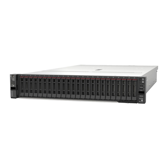
- Page 26 Drive activity LED Drive status LED Front I/O assembly with diagnostics panel Rack latch (right) Pull-out information tab Drive bays (24) Rack latch (left) Note: For more information about each component, see “Front components overview” on page ThinkSystem SR665 Maintenance Manual...
- Page 27 Server models with 2.5-inch front drive bays (backplane-less) The following illustration shows the front view of server models with 2.5-inch front drive bays (backplane- less). Table 8. Components on the front of server models Callout Callout External diagnostics connector VGA connector (optional) Drive bay fillers(3) Front I/O assembly with diagnostics panel Rack latch (right)
- Page 28 Drive status LED Drive bay filler Front I/O assembly with diagnostics panel Pull-out information tab Rack latch (right) Drive bays (8) Rack latch (left) Note: For more information about each component, see “Front components overview” on page ThinkSystem SR665 Maintenance Manual...
- Page 29 Server models with twelve 3.5-inch front drive bays The following illustration shows the front view of server models with twelve 2.5-inch drive bays. Table 10. Components on the front of server models Callout Callout External diagnostics connector VGA connector (optional) Drive activity LED Drive status LED Front I/O assembly with diagnostics panel...
- Page 30 External diagnostics connector VGA connector (optional) Front I/O assembly with diagnostics panel Rack latch (right) Pull-out information tab Drive bay fillers (12) Rack latch (left) Note: For more information about each component, see “Front components overview” on page ThinkSystem SR665 Maintenance Manual...
- Page 31 Front components overview Diagnostics panel The diagnostics panel is integrated in front I/O assembly on some models. For information about the controls and status LEDs on the diagnostics panel, see “Diagnostics panel” on page 23. Drive LEDs Each hot-swap drive comes with an activity LED and status LED and the signals are controlled by the backplanes.
- Page 32 Pull-out information tab The Lenovo XClarity Controller network access label is attached on the pull-out information tab. The default Lenovo XClarity Controller hostname and the IPv6 Link Local Address (LLA) are provided on the tab. Rack latches If your server is installed in a rack, you can use the rack latches to help you slide the server out of the rack.
-
Page 33: Diagnostics Panel
Diagnostics panel The diagnostics panel provides controls, connectors, and LEDs. Note: Diagnostics panel with an LCD display is available for some models. For details, see “LCD diagnostics panel/handset” on page 26. Figure 6. Front I/O assembly for server models Table 12. Components on the front I/O assembly Callout Callout USB 3.1 Gen 1 connector... - Page 34 The server is connected to a network. Blinking Green The network is connected and active. None The server is disconnected from the network. Note: If no OCP 3.0 Ethernet adapter is installed, this LED is off. ThinkSystem SR665 Maintenance Manual...
- Page 35 System ID button with system ID LED Use this system ID button and the blue system ID LED to visually locate the server. A system ID LED is also located on the rear of the server. Each time you press the system ID button, the state of both the system ID LEDs changes.
-
Page 36: Lcd Diagnostics Panel/Handset
Notes: • The panel can be inserted or pulled out regardless of the system status. • When pulling out the panel, carefully hold it by the handle and avoid any hard pulling. ThinkSystem SR665 Maintenance Manual... - Page 37 Where to find the external LCD diagnostics handset Location Callout The external LCD diagnostics handset is connected to the server with an external cable. The LCD diagnostics handset that can be connected to the server with an external cable. The magnetic bottom with which the device can be attached to the top or side of the rack.
- Page 38 LCD diagnostics panel overview LCD display Scroll buttons (up/down/left/right). Press the scroll buttons to locate and select system information. Select button. Press the select button to select from the menu options. ThinkSystem SR665 Maintenance Manual...
- Page 39 Options flow diagram The LCD diagnostics panel/handset shows various system information. Navigate through the options with the scroll keys. Chapter 2 Server components...
- Page 40 CPU 1 Status: • Possible sources of the error Configuration Error System VPD Information Example Sub Menu Machine Type: xxxx Serial Num: xxxxxx • Machine type and serial number Universal Unique ID: • Universal Unique ID (UUID) xxxxxxxxxxxxxxxxxxxxxxxxxxxx ThinkSystem SR665 Maintenance Manual...
- Page 41 System Firmware Sub Menu Example UEFI UEFI (Inactive) • Firmware level (status) Build: D0E101P • Build ID Version: 1.00 • Version number Date: 2019-12-26 • Release date XCC Primary XCC Primary (Active) • Firmware level (status) Build: DVI399T • Build ID Version: 4.07 •...
- Page 42 This will request the BMC to reboot itself. • Request Virtual Reseat Hold √ for 3 seconds • Modify XCC Static IPv4 Address/Net mask/ Gateway • Modify System Name • Generate/Download FFDC Service Data • Remove FPGA Test Image ThinkSystem SR665 Maintenance Manual...
-
Page 43: Rear View
Rear view The rear of the server provides access to several connectors and components. Refer to the following rear view for different server models: • “Server model with eight PCIe slots” on page 34 • “Server model with four 2.5-inch rear drive bays and six PCIe slots” on page 35 •... - Page 44 USB 3.1 Gen 1 connectors (2) XClarity Controller Network connector Ethernet connectors on OCP 3.0 Ethernet adapter (optional, two or four connectors may be available) Note: For more information about each component, see “Rear components overview” on page 39. ThinkSystem SR665 Maintenance Manual...
- Page 45 Server models with four 2.5-inch rear drive bays and six PCIe slots Table 14. Components on the rear of the server Callout Callout PCIe slot 1 (on riser 1 assembly) PCIe slot 2 (on riser 1 assembly) PCIe slot 3 (on riser 1 assembly) PCIe slot 4 (on riser 2 assembly) PCIe slot 5 (on riser 2 assembly) PCIe slot 6 (on riser 2 assembly)
- Page 46 USB 3.1 Gen 1 connectors (2) XClarity Controller Network connector Ethernet connectors on OCP 3.0 Ethernet adapter (optional, two or four connectors may be available) Note: For more information about each component, see “Rear components overview” on page 39. ThinkSystem SR665 Maintenance Manual...
-
Page 47: Pcie Slot 1 (On Riser 1 Assembly)
Server models with two 3.5-inch rear drive bays and four PCIe slots Table 16. Components on the rear of the server Callout Callout PCIe slot 1 (on riser 1 assembly) PCIe slot 2 (on riser 1 assembly) PCIe slot 3 (on riser 1 assembly) PCIe slot 6 (on riser 2 assembly) 3.5-inch rear drive bays (2) Power supply 1... -
Page 48: Pcie Slot 3 (On Riser 1 Assembly)
USB 3.1 Gen 1 connectors (2) XClarity Controller Network connector Ethernet connectors on OCP 3.0 Ethernet adapter (optional, two or four connectors may be available) Note: For more information about each component, see “Rear components overview” on page 39. ThinkSystem SR665 Maintenance Manual... -
Page 49: Nmi Button
Rear components overview Drive LEDs Each hot-swap drive comes with an activity LED and status LED and the signals are controlled by the backplanes. Different colors and speeds indicate different activities or status of the drive. The following illustration shows the LEDs on a Hard disk drive or solid–state drive. Figure 7. -
Page 50: Vga Connector
The hot-swap redundant power supply helps you avoid significant interruption to the operation of the system when a power supply fails. You can purchase a power supply option from Lenovo and install the power supply to provide power redundancy without turning off the server. -
Page 51: Rear View Leds
Rear view LEDs The illustration in this section shows the LEDs on the rear of the server. Figure 8. Rear view LEDs of the server Table 18. LEDs on the rear of the server Callout Callout Ethernet link LED System ID LED Ethernet activity LED System error LED Power input LED... - Page 52 LED is off, replace the power supply. Power supply error LED • Yellow: The power supply has failed. To resolve the issue, replace the power supply. • Off: The power supply is working normally. ThinkSystem SR665 Maintenance Manual...
-
Page 53: System Board Components
System board components The illustration in this section shows the component locations on the system board. Figure 9. System board components NMI button CMOS battery (CR2032) TPM module connector M.2 power connector Serial port module connector Riser 1 power connector Riser 1 slot Internal USB connector OCP 3.0 Ethernet adapter connector... - Page 54 Riser 3 power connector PCIe connector 6 PCIe connector 8 PCIe connector 7 Power supply 1 connector PCIe connector 4 PCIe connector 5 Power supply 2 connector Riser 3 sideband connector Riser 2 slot Riser 2 power connector ThinkSystem SR665 Maintenance Manual...
-
Page 55: System Board Leds
System board LEDs The illustration in this section shows the LEDs on the system board. Figure 10. System board LEDs Table 19. LEDs on the system board Callout Callout System error LED System ID LED DIMM error LEDs (32) Fan error LEDs (6) FPGA error LED FPGA heartbeat LED FPGA power LED... - Page 56 Green The FPGA power is on. Blinking Green • Blinking (blinking slowly, about one flash per second): The FPGA power is off. • Blinking (blinking rapidly, about four flashes per second): The FPGA permission is delayed. ThinkSystem SR665 Maintenance Manual...
- Page 57 XCC heart beat LED The XCC heart beat LED helps you identify the XCC status. Status Color Description Green The XCC is not alive. Blinking Green The XCC is alive. None The XCC is not alive. Chapter 2 Server components...
-
Page 58: Switch Block And Jumper
• If there is a clear protective sticker on the top of the switch blocks, you must remove and discard it to access the switches. • Any system-board switch or jumper block that is not shown in the illustrations in this document is reserved. Figure 11. Switch block and jumper locations on system board ThinkSystem SR665 Maintenance Manual... - Page 59 Table 20. Switch block and jumper description Switch/jumper name Switch/jumper number Description • Pins 1 and 2: The jumper is in default setting. Clear CMOS jumper • Pins 2 and 3: Clear the real-time clock (RTC) registry. Switch 1 block •...
-
Page 60: Parts List
For more information about ordering the parts shown in Figure 12 “Server components” on page 51: https://datacentersupport.lenovo.com/us/en/products/servers/thinksystem/sr665/7d2w/parts Note: Depending on the model, your server might look slightly different from the illustration. Some parts are available only on some models. ThinkSystem SR665 Maintenance Manual... - Page 61 The parts listed in the following table are identified as one of the following: • Tier 1 customer replaceable unit (CRU): Replacement of Tier 1 CRUs is your responsibility. If Lenovo installs a Tier 1 CRU at your request with no service agreement, you will be charged for the installation.
- Page 62 • Tier 2 customer replaceable unit: You may install a Tier 2 CRU yourself or request Lenovo to install it, at no additional charge, under the type of warranty service that is designated for your server. • Field replaceable unit (FRU): FRUs must be installed only by trained service technicians.
- Page 63 Table 21. Parts listing (continued) Consumable Description Index Tier 1 CRU Tier 2 CRU Structural parts Rack latch (integrated with front I/O) √ Standard rack latch √ Front I/O assembly with LCD diagnostics √ panel Security bezel √ 1 x 3.5-inch drive bay filler √...
- Page 64 Table 21. Parts listing (continued) Consumable Description Index Tier 1 CRU Tier 2 CRU Structural parts RAID super capacitor module √ Memory module √ Power supply unit √ Power supply unit filler √ ThinkSystem SR665 Maintenance Manual...
-
Page 65: Power Cords
Several power cords are available, depending on the country and region where the server is installed. To view the power cords that are available for the server: 1. Go to: http://dcsc.lenovo.com/#/ 2. Click Preconfigured Model or Configure to order. 3. Enter the machine type and model for your server to display the configurator page. - Page 66 ThinkSystem SR665 Maintenance Manual...
-
Page 67: Chapter 3. Internal Cable Routing
Note: Disengage all latches, release tabs, or locks on cable connectors when you disconnect cables from the system board. Failing to release them before removing the cables will damage the cable sockets on the system board, which are fragile. Any damage to the cable sockets might require replacing the system board. © Copyright Lenovo 2019... -
Page 68: Front I/O Assembly
VGA connector on the system board External diagnostics cable on the left rack latch External LCD connector on the system board Front USB and panel cable on the right rack latch Front I/O and front USB connectors on the system board ThinkSystem SR665 Maintenance Manual... -
Page 69: Gpus
GPUs Use this section to understand the routing for GPUs. Figure 14. Cable routing for single-wide and double-wide GPU From Power connector on a single-wide GPU (on riser 3 GPU 1 connector on the system board assembly) Power connector on a double-wide GPU (on riser 1 or GPU Pwr connector on the riser card (on riser 1 or 2 2 assembly) assembly) - Page 70 Figure 15. Riser card 3 power and sideband connection From Power connector on the riser card Riser 3 power connector on the system board Sideband connector on the riser card Riser 3 sideband on the system board ThinkSystem SR665 Maintenance Manual...
- Page 71 Riser card 3 (x8/x8 or x16/x16 PCIe) cable connection Figure 16. Cable routing for riser card 3 (x8/x8 or x16/x16 PCIe) From PCIe connector 1-2 on the riser card PCIe connector 1-2 on the system board PCIe connectors 7 on the riser card PCIe connectors 7 on the system board PCIe connector 8on the riser card PCIe connector 8 on the system board...
-
Page 72: Raid Super Capacitor Modules
RAID adapter as shown. Figure 17. Connecting the RAID super capacitor module to the RAID adapter From RAID super capacitor module Supercap connecor on the RAID adapter ThinkSystem SR665 Maintenance Manual... -
Page 73: Internal Cff Raid/Hba/Expander Adapters (Power)
Internal CFF RAID/HBA/Expander adapters (power) Use the section to understand the power cable routing for internal CFF RAID/HBA/Expander adapter. Power cable routing for internal CFF RAID/HBA/Expander adapters Note: The illustration only involves power cable routing. For signal cable routing, see “2.5-inch/3.5-inch drive backplane (signal)”... -
Page 74: 7Mm Drives
Note: 7mm drives can only be installed in slot 6. Figure 18. Cable routing for 7mm drives From 7mm signal cable PCIe connector 5 on the system board Power cable 7mm power connector on the system board ThinkSystem SR665 Maintenance Manual... -
Page 75: M.2 Drives
M.2 drives This section provides cable routing information for the M.2 drives. M.2 drives can be installed on the standard air baffle (scenario 1), GPU air baffle (scenario 2), 2.5-inch middle drive cage (scenario 3), or 3.5-inch middle drive cage (scenario 4). The following illustration shows the cable connection for scenario 1. -
Page 76: Inch/3.5-Inch Drive Backplane (Power)
Figure 20. Power cabling for 3.5-inch chassis From Power 1 connector on backplane Front backplane 1 power connector on the system board Power 2 connector on backplane Front backplane 2 power connector on the system board ThinkSystem SR665 Maintenance Manual... - Page 77 Figure 21. Power cabling for 2.5-inch chassis From Power connector on backplane 1 Front backplane 1 power connector on the system board Power connector on backplane 2 Front backplane 2 power connector on the system board Power connector on backplane 3 Front backplane 3 power connector on the system board Chapter 3 Internal cable routing...
- Page 78 Middle drive backplanes Figure 22. Power cabling for 3.5-inch chassis From Power connector on backplane 5 Power connector on riser 1 or 2 assembly ThinkSystem SR665 Maintenance Manual...
- Page 79 Figure 23. Power cabling for 2.5-inch chassis From Power connector on backplane 5 and Power connector 1 and power connector 2 on riser 1 or 2 assembly backplane 6 Chapter 3 Internal cable routing...
- Page 80 Note: The illustration shows the cable routing for the 4 x 2.5-inch rear drive backplane, routing for the other rear drive backplanes are similar. Figure 24. Power cabling for 3.5-inch chassis or 2.5-inch chassis From Power connector on backplane 4 Power connector on riser 1or 2 assembly ThinkSystem SR665 Maintenance Manual...
-
Page 81: Inch/3.5-Inch Drive Backplane (Signal)
2.5-inch/3.5-inch drive backplane (signal) Use the section to understand the cable routing for signal cable connections for 2.5-inch/3.5-inch drive backplanes. 8 x 2.5-inch front drive bays (SAS/SATA) This section provides cable routing information for the server model with 8 x 2.5-inch SAS/SATA front drive bays. - Page 82 Figure 25. Cable routing for configuration 4 ThinkSystem SR665 Maintenance Manual...
-
Page 83: X 2.5-Inch Front Drive Bays (Anybay)
8 x 2.5-inch front drive bays (AnyBay) This section provides cable routing information for the server model with eight 2.5-inch front drive bays. The server model is configured with one 8 x 2.5-inch Anybay front drive backplane. Below lists all supported configurations with this front drive backplane. - Page 84 Note: For models that support Gen 3 and Gen4 adapters at the same slot, the illustration shows only the cable routing information for Gen 4 adapters, the routing and connector information is similar for Gen 3 adapters. Figure 26. Cable routing for configuration 2 ThinkSystem SR665 Maintenance Manual...
-
Page 85: X 2.5-Inch Front Drive Bays (Nvme)
8 x 2.5-inch front drive bays (NVMe) This section provides cable routing information for the server model with eight 2.5-inch front drive bays. The server model is configured with one 8 x 2.5-inch AnyBay front drive backplane (BP 1). Only onboard configuration is supported. - Page 86 The following illustration shows the cable routing for the configuration 1. Connections between connectors: ↔ ↔ ↔ ↔ , ... Figure 27. Cable routing for configuration 1 ThinkSystem SR665 Maintenance Manual...
-
Page 87: 16 X 2.5-Inch Front Drive Bays (Sas/Sata)
16 x 2.5-inch front drive bays (SAS/SATA) This section provides cable routing information for the server model with 16 x 2.5-inch SAS/SATA front drive bays. The server model is configured with two 8 x 2.5-inch SAS/SATA backplanes (BP 1 and BP 2). Below lists all supported configurations with these two front drive backplanes. - Page 88 Note: For models that support Gen 3 and Gen4 adapters at the same slot, the illustration shows only the cable routing information for Gen 4 adapters, the routing and connector information is similar for Gen 3 adapters. Figure 28. Cable routing for configuration 3 ThinkSystem SR665 Maintenance Manual...
-
Page 89: 16 X 2.5-Inch Front Drive Bays (Nvme)
16 x 2.5-inch front drive bays (NVMe) This section provides cable routing information for the server model with 16 x 2.5-inch NVMe front drive bays. The server model is configured with two 8 x 2.5-inch AnyBay backplanes (BP 1 and BP 2). Below lists the supported configuration with these two front drive backplanes. - Page 90 The following illustration shows the cable routing for the configuration 1. Connections between connectors: ↔ ↔ ↔ ↔ , ... Figure 29. Cable routing for configuration 1 ThinkSystem SR665 Maintenance Manual...
-
Page 91: 8Anybay)
16 x 2.5-inch front drive bays (8SAS+8AnyBay) This section provides cable routing information for the server model with 16 x 2.5-inch front drive bays (8SAS +8AnyBay). The following table lists the configurations for the server model with 16 x 2.5-inch front drive bays(8SAS +8AnyBay). - Page 92 PCIe 8 The following illustration shows the cable routing for the configuration 1, the routing for the other ↔ ↔ ↔ ↔ configurations is similar. Connections between connectors: , ... Figure 30. Cable routing for configuration 1 ThinkSystem SR665 Maintenance Manual...
-
Page 93: 16 X 2.5-Inch Front Drive Bays (8Sas/Sata +8Nvme)
16 x 2.5-inch front drive bays (8SAS/SATA+8NVMe) This section provides cable routing information for the server model with 16 x 2.5-inch front drive bays (8SAS/SATA+8NVMe). The server model is configured with one 8 x 2.5-inch SAS/SATA backplane (BP 1) and one 8 x 2.5-inch AnyBay backplane (BP 2). - Page 94 SFF 8i RAID/HBA C 0, C 1 BP 1: SAS PCIe 6 PCIe 1, PCIe 2 BP 2: NVMe 0–1 BP 2: NVMe 2–3 PCIe 3 BP 2: NVMe 4–5 PCIe 7 BP 2: NVMe 6–7 PCIe 8 ThinkSystem SR665 Maintenance Manual...
- Page 95 The following illustration shows the cable routing for the configuration 3, the routing for the other ↔ ↔ ↔ ↔ configurations is similar. . Connections between connectors: , ... Note: For models that support Gen 3 and Gen4 adapters at the same slot, the illustration shows only the cable routing information for Gen 4 adapters, the routing and connector information is similar for Gen 3 adapters.
-
Page 96: 16 X 2.5-Inch Front Drive Bays (8Anybay +8Nvme)
C 0, C 1 6–7 Gen 4: C 0 BP 1: SAS Gen3: C 0, C 1 PCIe 4, PCIe 5 BP 2: NVMe 0–1 BP 2: NVMe 2–3 PCIe 6 BP 2: NVMe 4–5 PCIe 7 ThinkSystem SR665 Maintenance Manual... - Page 97 Storage controller Con- System board Front BP SFF 16i RAID/ fig. PCIe switch SFF 8i RAID/HBA BP 2: NVMe 6–7 PCIe 8 Chapter 3 Internal cable routing...
- Page 98 Note: For models that support Gen 3 and Gen4 adapters at the same slot, the illustration shows only the cable routing information for Gen 4 adapters, the routing and connector information is similar for Gen 3 adapters. Figure 32. Cable routing for configuration 2 ThinkSystem SR665 Maintenance Manual...
-
Page 99: 16Nvme)
24 x 2.5-inch front drive bays (8SAS/SATA+16NVMe) This section provides cable routing information for the server model with 24 x 2.5-inch front drive bays (8SAS/SATA+16NVMe). The server model is configured with one 8 x 2.5-inch SAS/SATA backplane (BP 1) and two 8 x 2.5-inch AnyBay backplanes (BP 2 and BP 3). - Page 100 Storage controller System board Front BP SFF 16i RAID/ nfig. PCIe switch SFF 8i RAID/HBA BP3: NVMe 6–7 PCIe 8 ThinkSystem SR665 Maintenance Manual...
- Page 101 The following illustration shows the cable routing for the configuration 2, the routing for the configuration 1 is ↔ ↔ ↔ ↔ similar. Connections between connectors: , ... Note: For models that support Gen 3 and Gen4 adapters at the same slot, the illustration shows only the cable routing information for Gen 4 adapters, the routing and connector information is similar for Gen 3 adapters.
-
Page 102: 8Anybay)
Depending on your server configurations, refer to one of the following sections for cable routing information. • Configuration 1 to 4: front drive bays only • Configuration 5 to 8: front drive bays and rear drive bays ThinkSystem SR665 Maintenance Manual... - Page 103 The following table shows the cable connections for all configurations: Configuration 1 to 4: (front drive bays only) Front: two 8 x 2.5-inch SAS/SATA backplanes and one 8 x 2.5-inch AnyBay backplane Storage controller Con- System board Front BP CFF 36i CFF 16i SFF 8i fig.
- Page 104 PCIe 8 BP 1: SAS BP 2: SAS BP 3: SAS PCIe 1, PCIe 2 BP 3: NVMe 0–1 BP 3: NVMe 2–3 PCIe 3 BP 3: NVMe 4–5 PCIe 7 BP3: NVMe 6–7 PCIe 8 ThinkSystem SR665 Maintenance Manual...
- Page 105 The following illustration shows the cable routing for the configuration 2, the routing for configuration 1, 3, ↔ ↔ ↔ ↔ and 4 is similar. Connections between connectors: , ... Note: For models that support Gen 3 and Gen4 adapters at the same slot, the illustration shows only the cable routing information for Gen 4 adapters, the routing and connector information is similar for Gen 3 adapters.
- Page 106 BP 4: SAS Gen 4: C 0 RAID/HBA Gen3: C 0, C PCIe 1, PCIe 2 BP 3: NVMe 0–1 BP 3: NVMe 2–3 PCIe 3 BP 3: NVMe 4–5 PCIe 7 BP3: NVMe 6–7 PCIe 8 ThinkSystem SR665 Maintenance Manual...
- Page 107 Front: two 8 x 2.5-inch SAS/SATA backplanes and one 8 x 2.5-inch AnyBay backplane Rear: one 4 x 2.5-inch SAS/SATA backplanes Storage controller nfi- System board Front BP Rear BP SFF 8i SFF 32i RAID/HBA RAID Slot 2: BP 1: SAS Gen 4: C 0/C 1 Gen3: C 0 Slot 3:...
- Page 108 Note: For models that support Gen 3 and Gen4 adapters at the same slot, the illustration shows only the cable routing information for Gen 4 adapters, the routing and connector information is similar for Gen 3 adapters. Figure 35. Cable routing for configuration 5 ThinkSystem SR665 Maintenance Manual...
-
Page 109: 24 X 2.5-Inch Front Drive Bays (16Sas/Sata+8Nvme)
24 x 2.5-inch front drive bays (16SAS/SATA+8NVMe) This section provides cable routing information for the server model with 24 x 2.5-inch front drive bays (16SAS/SATA+8NVMe). The server model is configured with two 8 x 2.5-inch SAS/SATA backplane (BP 1 and BP 2) and one 8 x 2.5- inch AnyBay backplanes (BP 3). - Page 110 PCIe 1, PCIe 2 BP 3: NVMe 0–1 BP 3: NVMe 2–3 PCIe 3 BP 3: NVMe 4–5 PCIe 7 BP3: NVMe 6–7 PCIe 8 BP 1: SAS BP 2: SAS PCIe 1, PCIe 2 BP 3: NVMe 0–1 ThinkSystem SR665 Maintenance Manual...
- Page 111 BP 3: NVMe 2–3 PCIe 3 BP 3: NVMe 4–5 PCIe 7 BP3: NVMe 6–7 PCIe 8 Chapter 3 Internal cable routing...
- Page 112 The following illustration shows the cable routing for the configuration 4, the routing for the other ↔ ↔ ↔ ↔ configurations is similar. Connections between connectors: , ... Figure 36. Cable routing for configuration 4 ThinkSystem SR665 Maintenance Manual...
-
Page 113: 24 X 2.5-Inch Front Drive Bays (Sas/Sata)
24 x 2.5-inch front drive bays (SAS/SATA) This section provides cable routing information for the server model with 24 x 2.5-inch front drive bays (SAS/ SATA). The server model is configured with three 8 x 2.5-inch SAS/SATA backplane (BP 1, BP 2, and BP 3). Below lists all supported configurations with these three front drive backplanes. - Page 114 Gen 3: C 0/C 1 Gen 4: C 0 BP 2: SAS Gen 3: C 0/C 1 Gen 4: C 0/C 2 BP 3: SAS Gen 3: C 0/C 1 BP 1: SAS BP 2: SAS BP 3: SAS ThinkSystem SR665 Maintenance Manual...
- Page 115 The following illustration shows the cable routing for the configuration 4, the routing for the other ↔ ↔ ↔ ↔ configurations is similar. Connections between connectors: , ... Figure 37. Cable routing for configuration 4 Chapter 3 Internal cable routing...
- Page 116 Gen 4: C 0 Gen 3: C 0/C 1 Slot 3: BP 2: SAS Gen 4: C 0 Gen 3: C 0/C 1 Slot 5: BP 3: SAS Gen 4: C 0/C 2 Gen 3: C 0/C 1 ThinkSystem SR665 Maintenance Manual...
- Page 117 Storage controller Configura- Front BP Rear BP tion option SFF 8i RAID/HBA SFF 32i RAID Slot 6: BP 4: SAS Gen 4: C 0 Gen 3: C 0/C 1 BP 1: SAS BP 2: SAS BP 3: SAS BP 4: SAS Chapter 3 Internal cable routing...
- Page 118 The following illustration shows the cable routing for the configuration 4, the routing for the other ↔ ↔ ↔ ↔ configurations is similar. Connections between connectors: , ... Figure 38. Cable routing for configuration 5 ThinkSystem SR665 Maintenance Manual...
- Page 119 Configuration 9 to 11: (front drive bays, mid drive bays, and rear drive bays) Front: three 8 x 2.5-inch SAS/SATA backplanes (BP 1, BP 2, and BP 3) Mid: two 4 x 2.5-inch SAS/SATA backplanes (BP 5 and BP 6) Rear: one 8 x 2.5-inch SAS/SATA backplane (BP 4) Storage controller Config.
- Page 120 The following illustration shows the cable routing for the configuration 10. the routing for the other ↔ ↔ ↔ ↔ configurations is similar. Connections between connectors: , ... Figure 39. Cable routing for configuration 10 ThinkSystem SR665 Maintenance Manual...
-
Page 121: 24 X 2.5-Inch Front Drive Bays (Nvme)
24 x 2.5-inch front drive bays (NVMe) This section provides cable routing information for the server model with 24 x 2.5-inch front drive bays (NVMe). The server model is configured with three 8 x 2.5-inch AnyBay backplanes (BP 1, BP 2, and BP 3). Below lists all supported configurations with these three front drive backplanes. - Page 122 BP3: NVMe 2–3 PCIe 8 Slot 4 BP3: NVMe 4–5, NVMe 6–7 C 0, C 1 The following illustration shows the cable routing for the configuration 4. Connections between connectors: ↔ ↔ ↔ ↔ , ... ThinkSystem SR665 Maintenance Manual...
- Page 123 Figure 40. Cable routing for configuration 1 Chapter 3 Internal cable routing...
- Page 124 BP 6: NVMe 0–1, NVMe 2–3 C 0, C 1, C 2, C 3 The following illustration shows the cable routing for the configuration 2. Connections between connectors: ↔ ↔ ↔ ↔ , ... Figure 41. Cable routing for configuration 2 ThinkSystem SR665 Maintenance Manual...
-
Page 125: X 3.5-Inch Front Drive Bays (Sas/Sata)
8 x 3.5-inch front drive bays (SAS/SATA) This section provides cable routing information for the server model with 8 x 2.5-inch SAS/SATA front drive bays. The server model is configured with one 8 x 3.5-inch SAS/SATA front drive backplane. Below lists all supported configurations with this front drive backplane. - Page 126 Figure 42. Cable routing for configuration 2 ThinkSystem SR665 Maintenance Manual...
-
Page 127: 12 X 3.5-Inch Front Drive Bays (Sas/Sata)
12 x 3.5-inch front drive bays (SAS/SATA) This section provides cable routing information for the server model with 12 x 3.5-inch SAS/SATA front drive bays. The server model is configured with one 12 x 3.5-inch SAS/SATA front drive backplane. Below lists all supported configurations with this front drive backplane. - Page 128 Note: For models that support Gen 3 and Gen4 adapters at the same slot, the illustration shows only the cable routing information for Gen 4 adapters, the routing and connector information is similar for Gen 3 adapters. Figure 43. Cable routing for configuration 2 ThinkSystem SR665 Maintenance Manual...
- Page 129 The following table shows the cable connections for all configurations: Configuration 3: (front drive bays and mid drive bays) Front: one 12 x 3.5-inch SAS/SATA backplane Mid: two 4 x 2.5-inch NVMe backplanes Storage controller Con- System board Front BP Mid BP fig.
- Page 130 Note: For models that support Gen 3 and Gen4 adapters at the same slot, the illustration shows only the cable routing information for Gen 4 adapters, the routing and connector information is similar for Gen 3 adapters. ThinkSystem SR665 Maintenance Manual...
- Page 131 Figure 45. Cable routing for configuration 6 Chapter 3 Internal cable routing...
- Page 132 Note: For models that support Gen 3 and Gen4 adapters at the same slot, the illustration shows only the cable routing information for Gen 4 adapters, the routing and connector information is similar for Gen 3 adapters. Figure 46. Cable routing for configuration 10 ThinkSystem SR665 Maintenance Manual...
- Page 133 Chapter 3 Internal cable routing...
-
Page 134: 12 X 3.5-Inch Front Drive Bays (Anybay)
Depending on your server configurations, refer to one of the following sections for cable routing information. • “Configuration 1: front drive bays only” on page 125 • Configuration 2 and 3: front drive bays and rear drive bays • Configuration 4: front drive bays, mid drive bays, and rear drive bays ThinkSystem SR665 Maintenance Manual... - Page 135 The following table shows the cable connections for all configurations: Configuration 1: (front drive bays only) Front: one 12 x 3.5-inch AnyBay backplane Storage controller Con- System board Front BP fig. SFF 16i RAID/HBA NVMe 0–1 PCIe 1, PCIe 2 NVMe 2–3 PCIe 3 NVMe 4–5...
- Page 136 NVMe 8–9 PCIe 7 NVMe 10–11 PCIe 8 Gen 4: C 0 SAS 0, SAS 1 Gen3: C 1 Gen 4: C 1 SAS 2 Gen3: C 0 Gen 4: C 0 BP 4: Gen3: C 0 ThinkSystem SR665 Maintenance Manual...
- Page 137 Configuration 4: (front drive bays, mid drive bays, and rear drive bays) Front: one 12 x 3.5-inch AnyBay backplane Mid: one 4 x 3.5-inch AnyBay backplane Rear: one 4 x 3.5-inch AnyBay backplane Storage controller Con- System board Front BP Rear BP fig.
- Page 138 Note: For models that support Gen 3 and Gen4 adapters at the same slot, the illustration shows only the cable routing information for Gen 4 adapters, the routing and connector information is similar for Gen 3 adapters. Figure 47. Cable routing for configuration 4 ThinkSystem SR665 Maintenance Manual...
-
Page 139: Chapter 4. Hardware Replacement Procedures
Go to to download firmware updates for your server. ThinkSystem SR665 Drivers and Software Important: Some cluster solutions require specific code levels or coordinated code updates. If the component is part of a cluster solution, verify that the latest level of code is supported for the cluster solution before you update the code. -
Page 140: System Reliability Guidelines
• Avoid loose-fitting clothing, particularly around your forearms. Button or roll up long sleeves before working inside the server. • Prevent your necktie, scarf, badge rope, or hair from dangling into the server. • Remove jewelry, such as bracelets, necklaces, rings, cuff links, and wrist watches. ThinkSystem SR665 Maintenance Manual... -
Page 141: Handling Static-Sensitive Devices
• Remove items from your shirt pocket, such as pens and pencils, in case they fall into the server as you lean over it. • Avoid dropping any metallic objects, such as paper clips, hairpins, and screws, into the server. Handling static-sensitive devices Review these guidelines before you handle static-sensitive devices to reduce the possibility of damage from electrostatic discharge. -
Page 142: Technical Rules
The following lists the required fans when different processors are installed. Fan type Server model With GPUs/CX6 adapters Without GPUs/CX6 adapter 8 x 2.5'', 8 x 3.5'', Standard Performance 16 x 2.5'' 12 x 3.5'', 24 x Performance Performance 2.5'' backplane-less Performance Performance ThinkSystem SR665 Maintenance Manual... - Page 143 Technical rules for DIMMs The following figure and table help you locate the memory slots and channels on the system board. Figure 48. Memory module locations Chapter 4 Hardware replacement procedures...
- Page 144 DRAM based DIMMs can be mixed, but not in the same channel. • Type: DIMMs of different base module types can be mixed, but not in the same channel. • Vendor: DIMMs from different vendors can be mixed in the same channel. ThinkSystem SR665 Maintenance Manual...
-
Page 145: Technical Rules For Processor And Heat
Technical rules for processor and heat sink Understanding the technical rules helps you choose the correct heat sinks, fans, and other components based on what processors are configured for your server. Supported heat sinks for processors The following lists the required heat sinks and fans when different processors are installed. With Mid bays/Full-length GPUs Without Mid bays/Full-length GPUs Processor TDP... - Page 146 Note: The operating speed and total memory capacity depend on the processor model and UEFI settings. The following figure and table help you locate the memory slots and channels on the system board. Figure 49. Memory module locations ThinkSystem SR665 Maintenance Manual...
- Page 147 Table 24. Memory slot and channel identification Channel Slot number Rules you need to follow when installing or replacing a DIMM. • Slot: – When a data bus daisy chain topology is used: populate DIMMs from farthest slot (slot 1) to closest slot (slot 0) to the processor on a per-channel basis.
- Page 148 ThinkSystem SR665 Maintenance Manual...
-
Page 149: Drive Bay Configurations And Requirements
• Up to eight 2.5-inch SAS/SATA or two 7mm SAS/SATA rear drives • Up to two M.2 SATA/NVMe drives For a list of supported drives, see: https://static.lenovo.com/us/en/serverproven/index.shtml Drive bay combinations The following table shows the supported drive bay combinations for the chassis with 3.5-inch/2.5-inch front drive bays. - Page 150 The following table shows the supported drive bay combinations when two processors are installed. Table 26. 3.5-inch drive bay combinations matrix Front bays Middle bays Rear bays Total 3.5''Any- 3.5''SAS/ 3.5'' SAS/ 2.5'' SAS/ drives 2.5'' NVMe 3.5'' SAS/SATA SATA SATA SATA ThinkSystem SR665 Maintenance Manual...
- Page 151 Table 27. 2.5-inch drive bay configuration matrix Front bays Middle bays Rear bays Total 2.5''Any- 2.5''SAS/ 2.5''N- 2.5''SAS/ drives 2.5''NVMe 2.5''SAS/SATA SATA SATA 8+8+8 8+8+8 8+8+8 8+8+8 8+8+8 8+8+8 Chapter 4 Hardware replacement procedures...
- Page 152 – Performance fans (speed of 18000 RPM) must be installed. – The processor TDP must be lower than or equal to 155 watts. – The ambient temperature must be lower than or equal to 35°C (95°F). ThinkSystem SR665 Maintenance Manual...
- Page 153 • To support a rear drive cage: – Performance fans (speed of 18000 RPM) must be installed. – The processor TDP must be lower than or equal to 225 watts. – The ambient temperature must be lower than or equal to 35°C (95°F). Chapter 4 Hardware replacement procedures...
-
Page 154: Technical Rules For Pcie Slots
• When one or more SED drives are installed, the following internal SAS HBA adapters are not supported: – 430-8i – 430-16i – 440-16i • One super capacitor module is required for each 930/940 series internal RAID or 940-8e RAID/HBA adapter. ThinkSystem SR665 Maintenance Manual... - Page 155 • Gen 3 and Gen 4 SFF RAID adapters are not supported when 7mm drives or M.2 drives are installed. • Gen 3 and Gen 4 SFF RAID adapters are available on the following server models when one processor is installed.
- Page 156 Two processors are installed 1,4,2,5,3,6,7,8 Notes: The following two Mellanox ConnectX-6 adapters are always installed on slot 1: – Mellanox ConnectX-6 HDR IB/200GbE Single Port x16 PCIe Adapter – Mellanox HDR Auxiliary x16 PCIe 3.0 Connection Card ThinkSystem SR665 Maintenance Manual...
-
Page 157: Technical Rules For Gpu
Technical rules for GPU Understanding the technical rules helps you choose the correct GPUs and install them in the supported slots based on what is configured for your server. Type Maximum supported Tesla V100S/V100 full-height, full-length, double-wide Tesla T4/Quadro P620 low-profile, half-length, single-wide Notes: •... -
Page 158: Technical Rules For System Fans
• If there is an OCP 3.0 Ethernet adapter installed, when the system is powered off but still plugged in to AC power, fan 1 and fan 2 will continue to spin at a much lower speed. This is the system design to provide proper cooling for the OCP 3.0 Ethernet adapter. ThinkSystem SR665 Maintenance Manual... -
Page 159: Air Baffle Replacement
Air baffle replacement Use this information to remove and install the air baffle. • “Remove the air baffle” on page 149 • “Install the air baffle” on page 152 Remove the air baffle Use this information to remove the air baffle. About this task Attention: For proper cooling and airflow, install the air baffle before you turn on the server. - Page 160 2. If there is a RAID super capacitor module installed on the air baffle, disconnect the RAID super capacitor module cable first. 3. If there is a GPU installed on the air baffle, remove the GPU first. See “Remove a GPU adapter” on page 169. ThinkSystem SR665 Maintenance Manual...
- Page 161 Step 2. Grasp the air baffle and carefully lift it out of the server. Note: The illustrated air baffle is a standard air baffle. The removal procedure is the same for GPU air baffle. Figure 50. Removal of the standard air baffle Chapter 4 Hardware replacement procedures...
-
Page 162: Install The Air Baffle
• Prevent exposure to static electricity, which might lead to system halt and loss of data, by keeping static- sensitive components in their static-protective packages until installation, and handling these devices with an electrostatic-discharge wrist strap or other grounding system. A video for this task is available at: • Youtube: https://www.youtube.com/playlist?list=PLYV5R7hVcs-Bz2XIeLEfGcrLGm9TSY_yt • Youku: http://list.youku.com/albumlist/show/id_52339612.html ThinkSystem SR665 Maintenance Manual... - Page 163 About this task Step 1. Check your server and ensure that: • No tools or loose screws are left inside your server. • All components have been reassembled correctly. • All cables inside the server have been properly routed and they will not interfere with installing the air baffle.
- Page 164 See “Install a super capacitor module on the air baffle” on page 293. 2. If you have removed a GPU, reinstall it. See “Install a GPU adapter” on page 172. 3. Complete the parts replacement. See “Complete the parts replacement” on page 397. ThinkSystem SR665 Maintenance Manual...
-
Page 165: Cable Wall Brackets Replacement (Full-Heigh/Half-Height)
Cable wall brackets replacement (full-heigh/half-height) Use this information to remove and install the full-height or half-height cable wall brackets. Your server supports two full-height or half-height cable wall brackets on the left and right side of the system board: • Half-height: designed for most models; •... - Page 166 Lift up the brakets from the system board as shown. After you finish 1. Connect any cables. See Chapter 3 “Internal cable routing” on page 57. 2. Complete the parts replacement. See “Complete the parts replacement” on page 397. ThinkSystem SR665 Maintenance Manual...
- Page 167 Chapter 4 Hardware replacement procedures...
-
Page 168: Install The Cable Wall Brackets
• Prevent exposure to static electricity, which might lead to system halt and loss of data, by keeping static- sensitive components in their static-protective packages until installation, and handling these devices with an electrostatic-discharge wrist strap or other grounding system. A video for this task is available at: • Youtube: https://www.youtube.com/playlist?list=PLYV5R7hVcs-Bz2XIeLEfGcrLGm9TSY_yt • Youku: http://list.youku.com/albumlist/show/id_52339612.html ThinkSystem SR665 Maintenance Manual... - Page 169 Procedure Step 1. Touch the static-protective package that contains the new cable holder to any unpainted surface on the outside of the server. Then, take the new cable holder out of the package and place it on a static-protective surface. Step 2.
-
Page 170: Cmos Battery Replacement
About this task Attention: • Lenovo has designed this product with your safety in mind. The lithium CMOS battery must be handled correctly to avoid possible danger. If you replace the CMOS battery, you must adhere to local ordinances or regulations. - Page 171 S004 CAUTION: When replacing the lithium battery, use only Lenovo specified part number or an equivalent type battery recommended by the manufacturer. If your system has a module containing a lithium battery, replace it only with the same module type made by the same manufacturer. The battery contains lithium and can explode if not properly used, handled, or disposed of.
-
Page 172: Install The Cmos Battery
The following tips describe information that you must consider when installing the CMOS battery. • Lenovo has designed this product with your safety in mind. The lithium battery must be handled correctly to avoid possible danger. If you install the CMOS battery, you must adhere to the following instructions. - Page 173 Procedure Step 1. Touch the static-protective package that contains the CMOS battery to any unpainted surface on the outside of the server. Then, take the CMOS battery out of the package. Step 2. Install the CMOS battery. Ensure that the CMOS battery is seated in place. Figure 55.
-
Page 174: Front I/O Assembly Replacement
• Server models with eight 2.5-inch front drive bays • Server models with sixteen 2.5-inch front drive bays • “Remove the front I/O assembly” on page 165 • “Install the front I/O assembly” on page 167 ThinkSystem SR665 Maintenance Manual... -
Page 175: Remove The Front I/O Assembly
Remove the front I/O assembly Use this information to remove the front I/O assembly. About this task Attention: • Read “Installation Guidelines” on page 129 to ensure that you work safely. • Power off the server and disconnect all power cords for this task. •... - Page 176 2. Slide the media bay out of the front chassis. After you finish If you are instructed to return the old front I/O assembly, follow all packaging instructions and use any packaging materials that are provided. ThinkSystem SR665 Maintenance Manual...
-
Page 177: Install The Front I/O Assembly
Install the front I/O assembly Use this information to install the front I/O assembly. About this task Attention: • Read “Installation Guidelines” on page 129 to ensure that you work safely. • Prevent exposure to static electricity, which might lead to system halt and loss of data, by keeping static- sensitive components in their static-protective packages until installation, and handling these devices with an electrostatic-discharge wrist strap or other grounding system. - Page 178 After you finish 1. Connect the cables of the front I/O assembly to the system board. See “Front I/O assembly” on page 58. 2. Complete the parts replacement. See “Complete the parts replacement” on page 397. ThinkSystem SR665 Maintenance Manual...
-
Page 179: Gpu Replacement
GPU replacement Use this information to remove and install a GPU adapter. • “Remove a GPU adapter” on page 169 • “Install a GPU adapter” on page 172 Remove a GPU adapter Use this information to remove a GPU adapter. About this task Attention: •... - Page 180 Depending on the GPU type, remove the GPU air baffle filler or extender for the GPU adapter. • For a single wide GPU adapter (for example, NVIDIA V100 GPU): Figure 58. Removing the add-on air baffle for a single-wide GPU adapter ThinkSystem SR665 Maintenance Manual...
- Page 181 • For a double wide GPU adapter (for example, NVIDIA T4 GPU): Figure 59. Removing the GPU air baffle filler for a double wide GPU adapter Step 4. Disconnect the power cable from the GPU adapter. Step 5. Remove the GPU adapter from the riser bracket. See “Remove a PCIe adapter and riser 1/2 assembly”...
-
Page 182: Install A Gpu Adapter
• Use any documentation that comes with the GPU adapter and follow those instructions in addition to the instructions in this topic. A video for this task is available at: • Youtube: https://www.youtube.com/playlist?list=PLYV5R7hVcs-Bz2XIeLEfGcrLGm9TSY_yt • Youku: http://list.youku.com/albumlist/show/id_52339612.html ThinkSystem SR665 Maintenance Manual... - Page 183 Procedure Step 1. Depending on the GPU type, install the GPU air baffle filler or extender for the GPU adapter. • For a double-wide GPU adapter (for example, NVIDIA V100 GPU): Figure 60. Installing the GPU air baffle filler for a double-wide GPU adapter Chapter 4 Hardware replacement procedures...
- Page 184 Install the riser assembly. See “Install a PCIe adapter and riser 1/2 assembly” on page 350 and “Install a PCIe adapter and riser 3 assembly” on page 359. After you finish Complete the parts replacement. See “Complete the parts replacement” on page 397. ThinkSystem SR665 Maintenance Manual...
-
Page 185: Hot-Swap Drive Replacement
Hot-swap drive replacement Use this information to remove and install a hot-swap drive. You can remove or install a hot-swap drive without turning off the server, which helps you avoid significant interruption to the operation of the system. Notes: • The term “hot-swap drive” refers to all the supported types of hot-swap hard disk drives, hot-swap solid- state drives, and hot-swap NVMe drives. -
Page 186: Remove A Hot-Swap Drive
If the drive bay numbers come with the term “NVMe”, it indicates the installed drives are NVMe drives. A video for this task is available at: • Youtube: https://www.youtube.com/playlist?list=PLYV5R7hVcs-Bz2XIeLEfGcrLGm9TSY_yt • Youku: http://list.youku.com/albumlist/show/id_52339612.html ThinkSystem SR665 Maintenance Manual... - Page 187 Procedure Step 1. If the security bezel is installed, remove it first. See “Remove the security bezel” on page 362. Step 2. Slide the release latch to the left to open the drive tray handle. Figure 62. Opening the drive tray handle Step 3.
-
Page 188: Install A Hot-Swap Drive
• Prevent exposure to static electricity, which might lead to system halt and loss of data, by keeping static- sensitive components in their static-protective packages until installation, and handling these devices with an electrostatic-discharge wrist strap or other grounding system. A video for this task is available at: • Youtube: https://www.youtube.com/playlist?list=PLYV5R7hVcs-Bz2XIeLEfGcrLGm9TSY_yt • Youku: http://list.youku.com/albumlist/show/id_52339612.html ThinkSystem SR665 Maintenance Manual... - Page 189 Procedure Step 1. Touch the static-protective package that contains the drive to any unpainted surface on the outside of the server. Then, take the drive out of the package and place it on a static-protective surface. Note: Ensure that drive installation meets “Drive bay configurations and requirements” on page 139.
- Page 190 1. Reinstall the security bezel if you have removed it. See “Install the security bezel” on page 365. 2. Use the Lenovo XClarity Provisioning Manager Lite to configure the RAID if necessary. For more information, see: https://sysmgt.lenovofiles.com/help/topic/LXPMv3/LXPMv3_introduction.html ThinkSystem SR665 Maintenance Manual...
-
Page 191: Hot-Swap Drive Backplane Replacement
Hot–swap drive backplane replacement Use this information to remove and install a hot-swap-drive backplane. Front drive backplane replacement: • “Remove the front 2.5-inch-drive backplane” on page 182 • “Install the front 2.5-inch-drive backplane” on page 185 • “Remove the front 3.5-inch-drive backplane” on page 194 •... -
Page 192: Remove The Front 2.5-Inch-Drive Backplane
• Prevent exposure to static electricity, which might lead to system halt and loss of data, by keeping static- sensitive components in their static-protective packages until installation, and handling these devices with an electrostatic-discharge wrist strap or other grounding system. A video for this task is available at: • Youtube: https://www.youtube.com/playlist?list=PLYV5R7hVcs-Bz2XIeLEfGcrLGm9TSY_yt • Youku: http://list.youku.com/albumlist/show/id_52339612.html ThinkSystem SR665 Maintenance Manual... - Page 193 Procedure Note: Depending on the specific type, your backplane might look different from the illustration in this topic. Step 1. Prepare your server. Remove the top cover. See “Remove the top cover” on page 392. Remove the system fan cage for easier operation. See “Remove a system fan” on page 381. Remove all the installed drives and fillers (if any) from the drive bays.
- Page 194 If you are instructed to return the old backplane, follow all packaging instructions and use any packaging materials that are provided. ThinkSystem SR665 Maintenance Manual...
-
Page 195: Install The Front 2.5-Inch-Drive Backplane
Install the front 2.5-inch-drive backplane Use this information to install the front 2.5-inch-drive backplane. About this task Your server supports two SATA/SAS 8-bay backplanes and one Anybay 8-bay backplane. The two SATA/ SAS 8-bay backplanes should be installed to drive bays 0–7 and drive bays 8–15, and the Anybay 8-bay backplane should be installed to drive bays 16–23. - Page 196 Then, take the new backplane out of the package and place it on a static- protective surface. Step 2. Connect the cables to the backplane. See “2.5-inch/3.5-inch drive backplane (power)” on page 66 and “2.5-inch/3.5-inch drive backplane (signal)” on page 71. ThinkSystem SR665 Maintenance Manual...
- Page 197 Step 3. Install the 2.5-inch-drive front backplane. Figure 67. 2.5-inch-drive backplane installation Align the bottom of the backplane in the slots on the bottom of the chassis. Rotate the backplane to the vertical position and align the holes in the backplane with the pins on the chassis and press the backplane into position.
-
Page 198: Remove The Middle Or Rear 2.5-Inch-Drive
• Depending on the specific type, your backplane might look different from the illustration in this topic. A video for this task is available at: • Youtube: https://www.youtube.com/playlist?list=PLYV5R7hVcs-Bz2XIeLEfGcrLGm9TSY_yt • Youku: http://list.youku.com/albumlist/show/id_52339612.html ThinkSystem SR665 Maintenance Manual... - Page 199 Procedure Note: The illustration shows removing the backplane from the rear drive cage. The procedure is the same for removing the backplane from the middle drive cage. Step 1. Prepare your server. 1. Remove the top cover. See “Remove the top cover” on page 392. 2.
-
Page 200: Backplane
Carefully lift the backplane out of the drive cage. Step 3. Record the cable connections on the backplane and then disconnect all cables from the backplane. See “2.5-inch/3.5-inch drive backplane (power)” on page 66 and “2.5-inch/3.5-inch drive backplane (signal)” on page 71. ThinkSystem SR665 Maintenance Manual... -
Page 201: Install The Middle Or Rear 2.5-Inch-Drive
Install the middle or rear 2.5-inch-drive backplane Use this information to install the middle or rear 2.5-inch-drive backplane. About this task Your server supports: • Two types of middle 2.5-inch-drive backplane – 4 x 2.5-inch SAS/SATA backplane – 4 x 2.5-inch NVMe backplane •... - Page 202 The release latches will secure the backplane in place. Figure 70. Installing the 4 x 2.5-inch-drive backplane ThinkSystem SR665 Maintenance Manual...
- Page 203 Figure 71. Installing the 8 x 2.5-inch-drive backplane After you finish 1. Reinstall all the drives and fillers (if any) into the drive bays. See “Install a hot-swap drive” on page 178. 2. Complete the parts replacement. See “Complete the parts replacement” on page 397. Chapter 4 Hardware replacement procedures...
-
Page 204: Remove The Front 3.5-Inch-Drive Backplane
• Prevent exposure to static electricity, which might lead to system halt and loss of data, by keeping static- sensitive components in their static-protective packages until installation, and handling these devices with an electrostatic-discharge wrist strap or other grounding system. A video for this task is available at: • Youtube: https://www.youtube.com/playlist?list=PLYV5R7hVcs-Bz2XIeLEfGcrLGm9TSY_yt • Youku: http://list.youku.com/albumlist/show/id_52339612.html ThinkSystem SR665 Maintenance Manual... - Page 205 Procedure Note: Depending on the specific type, your backplane might look different from the illustration in this topic. Step 1. Prepare your server. Remove the top cover. See “Remove the top cover” on page 392. Remove the system fan cage for easier operation. See “Remove a system fan” on page 381. Remove all the installed drives and fillers (if any) from the drive bays.
-
Page 206: Install The Front 3.5-Inch-Drive Backplane
• Prevent exposure to static electricity, which might lead to system halt and loss of data, by keeping static- sensitive components in their static-protective packages until installation, and handling these devices with an electrostatic-discharge wrist strap or other grounding system. A video for this task is available at: • Youtube: https://www.youtube.com/playlist?list=PLYV5R7hVcs-Bz2XIeLEfGcrLGm9TSY_yt • Youku: http://list.youku.com/albumlist/show/id_52339612.html ThinkSystem SR665 Maintenance Manual... - Page 207 Procedure Step 1. Touch the static-protective package that contains the new backplane to any unpainted surface on the outside of the server. Then, take the new backplane out of the package and place it on a static- protective surface. Step 2. Connect the cables to the backplane.
-
Page 208: Remove The Middle Or Rear 3.5-Inch-Drive
• Prevent exposure to static electricity, which might lead to system halt and loss of data, by keeping static- sensitive components in their static-protective packages until installation, and handling these devices with an electrostatic-discharge wrist strap or other grounding system. A video for this task is available at: • Youtube: https://www.youtube.com/playlist?list=PLYV5R7hVcs-Bz2XIeLEfGcrLGm9TSY_yt • Youku: http://list.youku.com/albumlist/show/id_52339612.html ThinkSystem SR665 Maintenance Manual... - Page 209 Procedure Note: The illustration shows removing the backplane from the rear drive cage. The procedure is the same for removing the backplane from the middle drive cage. Step 1. Prepare your server. 1. Remove the top cover. See “Remove the top cover” on page 392. 2.
-
Page 210: Backplane
3. Carefully lift the backplane out of the drive cage. Step 3. Record the cable connections on the backplane and then disconnect all cables from the backplane. See “2.5-inch/3.5-inch drive backplane (power)” on page 66 and “2.5-inch/3.5-inch drive backplane (signal)” on page 71. ThinkSystem SR665 Maintenance Manual... -
Page 211: Install The Middle Or Rear 3.5-Inch-Drive
Install the middle or rear 3.5-inch-drive backplane Use this information to install the middle or rear 3.5-inch-drive backplane. About this task Your server supports: • One type of middle 3.5-inch-drive backplane – 4 x 3.5-inch SAS/SATA backplane • Two types of rear 3.5-inch-drive backplane –... - Page 212 The release latches will secure the backplane in place. Figure 76. Installing the 2 x 3.5-inch-drive backplane ThinkSystem SR665 Maintenance Manual...
-
Page 213: Remove The 7Mm Drive Backplane
Figure 77. Installing the 4 x 3.5-inch-drive backplane After you finish 1. Reinstall all the drives and fillers (if any) into the drive bays. See “Install a hot-swap drive” on page 178. 2. Complete the parts replacement. See “Complete the parts replacement” on page 397. Remove the 7mm drive backplane Use this information to remove the 7mm drive backplane. - Page 214 338. Step 2. Remove the 7mm drive backplane on the top. Figure 78. 7mm drive backplane removal (top) Remove the two screws as shown. Vertically lift the backplane up and put it aside. ThinkSystem SR665 Maintenance Manual...
-
Page 215: Install The 7Mm Drive Backplanes
Step 3. Remove the 7mm drive backplane at the bottom. Figure 79. 7mm drive backplane removal (bottom) Remove the screw as shown. Remove the backplane horizontally from the cage as shown. After you finish If you are instructed to return the old backplanes, follow all packaging instructions and use any packaging materials that are provided. - Page 216 Step 2. Connect the cables to the backplanes. See “7mm drives” on page 64. ThinkSystem SR665 Maintenance Manual...
- Page 217 Step 3. Install the 7mm drive backplane at the bottom. Figure 80. 7mm drive backplane installation (bottom) Align the pin on the cage and slightly slide the backplane into the cage until it is fully seated. Install the screw as shown. Step 4.
-
Page 218: Hot-Swap Power Supply Unit Replacement
Hot-swap power supply unit replacement Use this information to remove and install a power supply unit. • “Remove a hot-swap power supply unit” on page 209 • “Install a hot-swap power supply” on page 216 ThinkSystem SR665 Maintenance Manual... -
Page 219: Remove A Hot-Swap Power Supply Unit
Remove a hot-swap power supply unit Use this information to remove a power supply unit. About this task The following describes the information that you must consider when removing a power supply: Note: If the power supply unit to be removed is the only one installed, the power supply is non-hot-swap and before removing it, you must turn off the server first. - Page 220 2. Attach all cables to devices. 2. Remove power cords from outlet. 3. Attach signal cables to connectors. 3. Remove signal cables from connectors. 4. Attach power cords to outlet. 4. Remove all cables from devices. 5. Turn device ON. ThinkSystem SR665 Maintenance Manual...
- Page 221 Safety information for DC power supplies CAUTION: 240 V dc input (input range: 180-300 V dc) is supported in Chinese Mainland ONLY. Power supply with 240 V dc input cannot support hot plugging power cord function. Before removing the power supply with dc input, please turn off server or disconnect dc power sources at the breaker panel or by turning off the power source.
- Page 222 2. Remove the signal cables from the connectors. 4. Attach signal cables to other devices. 3. Remove all cables from the devices. 5. Connect power cords to their sources. 6. Turn ON all the power sources. ThinkSystem SR665 Maintenance Manual...
- Page 223 Attention: • Read “Installation Guidelines” on page 129 to ensure that you work safely. • Prevent exposure to static electricity, which might lead to system halt and loss of data, by keeping static- sensitive components in their static-protective packages until installation, and handling these devices with an electrostatic-discharge wrist strap or other grounding system.
- Page 224 Do not disconnect the power cord from the secondly replaced power supply until the power output LED for the firstly replaced power supply is lit. For the location of the power output LED, refer to “Rear view LEDs” on page 41. ThinkSystem SR665 Maintenance Manual...
- Page 225 Step 3. Press the release tab toward the handle and carefully pull the handle at the same time to slide the hot-swap power supply out of the chassis. Note: Slightly pull the power supply upwards when sliding the power supply out of the chassis, if you have installed one of the following CMA kits: •...
-
Page 226: Install A Hot-Swap Power Supply
• If you are replacing the existing power supply with a new power supply: – Use Lenovo Capacity Planner to calculate the required power capacity for what is configured for your server. More information about Lenovo Capacity Planner is available at: https://datacentersupport.lenovo.com/solutions/lnvo-lcp... - Page 227 Safety information for AC power supplies S035 CAUTION: Never remove the cover on a power supply or any part that has this label attached. Hazardous voltage, current, and energy levels are present inside any component that has this label attached. There are no serviceable parts inside these components.
- Page 228 2. Attach all cables to devices. 2. Remove power cords from outlet. 3. Attach signal cables to connectors. 3. Remove signal cables from connectors. 4. Attach power cords to outlet. 4. Remove all cables from devices. 5. Turn device ON. ThinkSystem SR665 Maintenance Manual...
- Page 229 Safety information for DC power supplies CAUTION: 240 V dc input (input range: 180-300 V dc) is supported in Chinese Mainland ONLY. Power supply with 240 V dc input cannot support hot plugging power cord function. Before removing the power supply with dc input, please turn off server or disconnect dc power sources at the breaker panel or by turning off the power source.
- Page 230 2. Remove the signal cables from the connectors. 4. Attach signal cables to other devices. 3. Remove all cables from the devices. 5. Connect power cords to their sources. 6. Turn ON all the power sources. ThinkSystem SR665 Maintenance Manual...
- Page 231 Attention: • Read “Installation Guidelines” on page 129 to ensure that you work safely. • Prevent exposure to static electricity, which might lead to system halt and loss of data, by keeping static- sensitive components in their static-protective packages until installation, and handling these devices with an electrostatic-discharge wrist strap or other grounding system.
- Page 232 1. Connect one end of the power cord to the new power supply connector; then, connect the other end of the power cord into a properly grounded electrical outlet. 2. If you have adjusted the CMA to gain access to the power supply bay, properly readjust the CMA back in place. ThinkSystem SR665 Maintenance Manual...
- Page 233 3. If the server is turned off, turn on the server. Ensure that both the power input LED and the power output LED on the power supply are lit, indicating that the power supply is operating properly. Chapter 4 Hardware replacement procedures...
-
Page 234: Internal Cff Adapter Replacement
Disconnect all cables from the adapter. See Chapter 3 “Internal cable routing” on page 57. Step 3. Lift the release pin, slightly slide the adapter as shown, and carefully lift it out of the chassis. Figure 87. Internal CFF RAID/HBA/RAID expander adapter removal ThinkSystem SR665 Maintenance Manual... - Page 235 After you finish If you are instructed to return the old adapter, follow all packaging instructions and use any packaging materials that are provided. Chapter 4 Hardware replacement procedures...
-
Page 236: Install The Internal Cff Raid/Hba/Raid
Figure 88. Internal CFF RAID/HBA adapter installation Step 4. Connect cables to the adapter. After you finish Complete the parts replacement. See “Complete the parts replacement” on page 397. ThinkSystem SR665 Maintenance Manual... - Page 237 Chapter 4 Hardware replacement procedures...
-
Page 238: Intrusion Switch Replacement
• Prevent exposure to static electricity, which might lead to system halt and loss of data, by keeping static- sensitive components in their static-protective packages until installation, and handling these devices with an electrostatic-discharge wrist strap or other grounding system. A video for this task is available at: • Youtube: https://www.youtube.com/playlist?list=PLYV5R7hVcs-Bz2XIeLEfGcrLGm9TSY_yt • Youku: http://list.youku.com/albumlist/show/id_52339612.html ThinkSystem SR665 Maintenance Manual... - Page 239 Procedure Step 1. If the server is installed in a rack, extend the server from the rack. Step 2. Remove the top cover. See “Remove the top cover” on page 392. Step 3. Remove the intrusion switch assembly from the fan cage as shown. Figure 89.
-
Page 240: Install The Intrusion Switch
• Prevent exposure to static electricity, which might lead to system halt and loss of data, by keeping static- sensitive components in their static-protective packages until installation, and handling these devices with an electrostatic-discharge wrist strap or other grounding system. A video for this task is available at: • Youtube: https://www.youtube.com/playlist?list=PLYV5R7hVcs-Bz2XIeLEfGcrLGm9TSY_yt • Youku: http://list.youku.com/albumlist/show/id_52339612.html ThinkSystem SR665 Maintenance Manual... - Page 241 Procedure Step 1. Touch the static-protective package that contains the new intrusion switch to any unpainted surface on the outside of the server. Then, take the new intrusion switch out of the package and place them on a static-protective surface. Step 2.
- Page 242 After you finish Complete the parts replacement. See “Complete the parts replacement” on page 397. ThinkSystem SR665 Maintenance Manual...
-
Page 243: M.2 Adapter And M.2 Drive Replacement
M.2 adapter and M.2 drive replacement Use this information to remove and install the M.2 adapter and M.2 drive. • “Remove the M.2 adapter and M.2 drive” on page 234 • “Adjust the retainer on the M.2 adapter” on page 237 •... -
Page 244: Remove The M.2 Adapter And M.2 Drive
• Prevent exposure to static electricity, which might lead to system halt and loss of data, by keeping static- sensitive components in their static-protective packages until installation, and handling these devices with an electrostatic-discharge wrist strap or other grounding system. A video for this task is available at: • Youtube: https://www.youtube.com/playlist?list=PLYV5R7hVcs-Bz2XIeLEfGcrLGm9TSY_yt • Youku: http://list.youku.com/albumlist/show/id_52339612.html ThinkSystem SR665 Maintenance Manual... - Page 245 Procedure Note: The M.2 adapter you want to remove might be different from the following illustrations, but the removal method is the same. Step 1. Remove the top cover. See “Remove the top cover” on page 392. Step 2. Disconnect the cables from the system board. Step 3.
- Page 246 Remove the M.2 adapter. Figure 94. M.2 adapter removal Loosen the screw and remove the M.2 adapter from the bracket. Open the retainer clip on the air baffle. Remove the M.2 adapter from the air baffle. ThinkSystem SR665 Maintenance Manual...
-
Page 247: Adjust The Retainer On The M.2 Adapter
Adjust the retainer on the M.2 adapter Use this information to adjust the retainer on the M.2 adapter. Attention: • Read “Installation Guidelines” on page 129 to ensure that you work safely. • Power off the server and disconnect all power cords for this task. •... - Page 248 Take the retainer out of the keyhole. Insert the retainer into the correct keyhole. Press both sides of the retainer. Slide the retainer backwards (toward the small opening of the keyhole) until it is seated in place. ThinkSystem SR665 Maintenance Manual...
-
Page 249: Install The M.2 Adapter And M.2 Drive
Install the M.2 adapter and M.2 drive Use this information to install the M.2 adapter and M.2 drive. Attention: • Read “Installation Guidelines” on page 129 to ensure that you work safely. • Power off the server and disconnect all power cords for this task. •... - Page 250 Step 2. Adjust the retainer on the M.2 adapter to accommodate the particular size of the M.2 drive you wish to install. See “Adjust the retainer on the M.2 adapter” on page 237. ThinkSystem SR665 Maintenance Manual...
- Page 251 Step 3. Locate the connector on the M.2 adapter. Note: Some M.2 adapters support two identical M.2 drives. Install the M.2 drive in slot 0 first. Slot 0 Slot 1 Figure 96. M.2 drive slot Step 4. Install the M.2 adapter into the M.2 tray. Figure 97.
-
Page 252: Middle Drive Cage Replacement
Step 6. Connect the cables to the system board. See “M.2 drives” on page 65. After you finish Use the Lenovo XClarity Provisioning Manager to configure the RAID. For more information, see: https://sysmgt.lenovofiles.com/help/topic/LXPMv3/LXPMv3_introduction.html Middle drive cage replacement Use this information to remove and install the middle 2.5-inch or 3.5-inch drive cage. - Page 253 • Youtube: https://www.youtube.com/playlist?list=PLYV5R7hVcs-Bz2XIeLEfGcrLGm9TSY_yt • Youku: http://list.youku.com/albumlist/show/id_52339612.html Procedure Step 1. Prepare your server. Remove the top cover. See “Remove the top cover” on page 392. Remove the system fan cage for easier operation. See “Remove the system fan cage” on page 387.
-
Page 254: Install The Middle 2.5-Inch Drive Cage
If you are instructed to return the old drive cage, follow all packaging instructions and use any packaging materials that are provided. Install the middle 2.5-inch drive cage Use this information to install the middle 2.5-inch drive cage. ThinkSystem SR665 Maintenance Manual... - Page 255 About this task The middle drive cage is supported on some server models at certain conditions. For detailed information, see “Drive bay configurations and requirements” on page 139. Attention: • Read “Installation Guidelines” on page 129 to ensure that you work safely. •...
-
Page 256: Remove The Middle 3.5-Inch Drive Cage
• Prevent exposure to static electricity, which might lead to system halt and loss of data, by keeping static- sensitive components in their static-protective packages until installation, and handling these devices with an electrostatic-discharge wrist strap or other grounding system. A video for this task is available at: ThinkSystem SR665 Maintenance Manual... - Page 257 • Youtube: https://www.youtube.com/playlist?list=PLYV5R7hVcs-Bz2XIeLEfGcrLGm9TSY_yt • Youku: http://list.youku.com/albumlist/show/id_52339612.html Procedure Step 1. Prepare your server. Remove the top cover. See “Remove the top cover” on page 392. Remove the system fan cage for easier operation. See “Remove the system fan cage” on page 387.
- Page 258 Figure 106. Closing the handle for the middle 3.5-inch drive cage After you finish If you are instructed to return the old drive cage, follow all packaging instructions and use any packaging materials that are provided. ThinkSystem SR665 Maintenance Manual...
-
Page 259: Install The Middle 3.5-Inch Drive Cage
Install the middle 3.5-inch drive cage Use this information to install the middle 3.5-inch drive cage. About this task The middle drive cage is supported on some server models at certain conditions. For detailed information, see “Drive bay configurations and requirements” on page 139. Attention: •... - Page 260 5. Rotate the handle to close it. After you finish 1. Connect cables from the backplanes to a RAID/HBA adapter. See Chapter 3 “Internal cable routing” on page 57. 2. Complete the parts replacement. See “Complete the parts replacement” on page 397. ThinkSystem SR665 Maintenance Manual...
-
Page 261: Memory Module Replacement
Memory module replacement Use this information to remove and install a memory module. • “Remove a memory module” on page 252 • “Memory module installation rules” on page 254 • “Install a memory module” on page 255 Chapter 4 Hardware replacement procedures... -
Page 262: Remove A Memory Module
– Do not insert memory modules while holding packages or passive components, which can cause package cracks or detachment of passive components by the high insertion force. A video for this task is available at: • Youtube: https://www.youtube.com/playlist?list=PLYV5R7hVcs-Bz2XIeLEfGcrLGm9TSY_yt • Youku: http://list.youku.com/albumlist/show/id_52339612.html ThinkSystem SR665 Maintenance Manual... - Page 263 Procedure Step 1. Remove the top cover. See “Remove the top cover” on page 392. Step 2. If your server comes with an air baffle, remove it. See “Remove the air baffle” on page 149. Step 3. Remove the memory module from the slot. Figure 109.
-
Page 264: Memory Module Installation Rules
Note: The operating speed and total memory capacity depend on the processor model and UEFI settings. The following figure and table help you locate the memory slots and channels on the system board. Figure 110. Memory module locations ThinkSystem SR665 Maintenance Manual... -
Page 265: Install A Memory Module
Table 30. Memory slot and channel identification Channel Slot number Rules you need to follow when installing or replacing a DIMM. • Slot: – When a data bus daisy chain topology is used: populate DIMMs from farthest slot (slot 1) to closest slot (slot 0) to the processor on a per-channel basis. - Page 266 – Do not insert memory modules while holding packages or passive components, which can cause package cracks or detachment of passive components by the high insertion force. A video for this task is available at: • Youtube: https://www.youtube.com/playlist?list=PLYV5R7hVcs-Bz2XIeLEfGcrLGm9TSY_yt • Youku: http://list.youku.com/albumlist/show/id_52339612.html ThinkSystem SR665 Maintenance Manual...
- Page 267 Procedure Step 1. Touch the static-protective package that contains the memory module to any unpainted surface on the outside of the server. Then, take the memory module out of the package and place it on a static-protective surface. Step 2. Locate the required memory module slot on the system board.
- Page 268 After you finish Complete the parts replacement. See “Complete the parts replacement” on page 397. ThinkSystem SR665 Maintenance Manual...
-
Page 269: Ocp 3.0 Ethernet Adapter Replacement
OCP 3.0 Ethernet adapter replacement Use this information to remove and install the OCP 3.0 Ethernet adapter. • “Remove the OCP 3.0 Ethernet adapter” on page 260 • “Install the OCP 3.0 Ethernet adapter” on page 262 Chapter 4 Hardware replacement procedures... -
Page 270: Remove The Ocp 3.0 Ethernet Adapter
• Prevent exposure to static electricity, which might lead to system halt and loss of data, by keeping static- sensitive components in their static-protective packages until installation, and handling these devices with an electrostatic-discharge wrist strap or other grounding system. A video for this task is available at: • Youtube: https://www.youtube.com/playlist?list=PLYV5R7hVcs-Bz2XIeLEfGcrLGm9TSY_yt • Youku: http://list.youku.com/albumlist/show/id_52339612.html ThinkSystem SR665 Maintenance Manual... - Page 271 Procedure Step 1. Remove the OCP 3.0 Ethernet adapter. Figure 112. OCP 3.0 Ethernet adapter removal 1. Loosen the thumbscrew that secures the card. 2. Pull out the OCP 3.0 Ethernet adapter. Step 2. Remove the OCP label. Figure 113. OCP label removal After you finish Reinstall a new OCP 3.0 Ethernet adapter or a card filler.
-
Page 272: Install The Ocp 3.0 Ethernet Adapter
• Prevent exposure to static electricity, which might lead to system halt and loss of data, by keeping static- sensitive components in their static-protective packages until installation, and handling these devices with an electrostatic-discharge wrist strap or other grounding system. A video for this task is available at: • Youtube: https://www.youtube.com/playlist?list=PLYV5R7hVcs-Bz2XIeLEfGcrLGm9TSY_yt • Youku: http://list.youku.com/albumlist/show/id_52339612.html ThinkSystem SR665 Maintenance Manual... - Page 273 Procedure Step 1. Touch the static-protective package that contains the new OCP 3.0 Ethernet adapter to any unpainted surface on the outside of the server. Then, take the new OCP 3.0 Ethernet adapter out of the package and place it on a static-protective surface. Step 2.
- Page 274 Figure 115. Attaching the OCP label Step 5. Connect the cables to the OCP 3.0 Ethernet adapter. After you finish Complete the parts replacement. See “Complete the parts replacement” on page 397. ThinkSystem SR665 Maintenance Manual...
-
Page 275: Processor And Heat Sink Replacement
Processor and heat sink replacement Use this information to remove and install a processor and heat sink. The server supports the second-generation AMD ® EPYC family of processors. The server supports three types of heat sinks. Depending on the specific type, the heat sink on your server might be different from that shown in the illustrations. -
Page 276: Remove A Heat Sink
• Prevent exposure to static electricity, which might lead to system halt and loss of data, by keeping static- sensitive components in their static-protective packages until installation, and handling these devices with an electrostatic-discharge wrist strap or other grounding system. A video for this task is available at: • Youtube: https://www.youtube.com/playlist?list=PLYV5R7hVcs-Bz2XIeLEfGcrLGm9TSY_yt • Youku: http://list.youku.com/albumlist/show/id_52339612.html ThinkSystem SR665 Maintenance Manual... - Page 277 Procedure Notes: • It may take some time for the heat sink to cool down after the system has been powered down. • The heat sink is necessary to maintain proper thermal conditions for the processor. Do not power on the server with the heat sink removed.
- Page 278 • If you are replacing a heat sink, install a new heat sink. See “Install a heat sink” on page 273. • If you are replacing a processor, remove the processor. See “Remove a processor” on page 269. ThinkSystem SR665 Maintenance Manual...
-
Page 279: Remove A Processor
Remove a processor Use this information to remove a processor. About this task Attention: • Read “Installation Guidelines” on page 129 to ensure that you work safely. • Power off the server and disconnect all power cords for this task. •... - Page 280 Step 3. Hold the blue tab of the processor carrier and slide the processor carrier out of the rail frame. After you finish Install a new processor. See “Install a processor” on page 271. ThinkSystem SR665 Maintenance Manual...
-
Page 281: Install A Processor
• See for a list of processors supported for your https://static.lenovo.com/us/en/serverproven/index.shtml server. All processors on the system board must have the same speed, number of cores, and frequency. • Before you install a new processor, update your system firmware to the latest level. See “Firmware updates”... - Page 282 Tighten the screws in the installation sequence shown on the force frame. Note: Use an ESD safe screwdriver and set the maximum torque value to 14.0 ± 0.5 inch-pounds. After you finish Install the heat sink. See “Install a heat sink” on page 273. ThinkSystem SR665 Maintenance Manual...
-
Page 283: Install A Heat Sink
Install a heat sink This task has instructions for installing a heat sink. About this task Attention: • Read “Installation Guidelines” on page 129 to ensure that you work safely. • Power off the server and disconnect all power cords for this task. •... - Page 284 2. Apply new thermal grease (TaiSol TC5288) in a quadrilateral design on the top of the processor. Note: Do not apply too much thermal grease. Too much thermal grease can result in excess grease coming in contact with and contaminating the processor socket. Figure 120. Applying thermal grease ThinkSystem SR665 Maintenance Manual...
- Page 285 Step 2. If you use a new heat sink, the thermal grease is pre-applied to the heat sink. Remove the protective cover and install the heat sink. Step 3. Orient the heat sink with the screw holes on the processor plate. The captive screws on the heat sink should align with the screw holes on the processor plate.
- Page 286 After you finish 1. Install the air baffle. See “Install the air baffle” on page 152. 2. Install any parts that you have removed. 3. Complete the parts replacement. See “Complete the parts replacement” on page 397. ThinkSystem SR665 Maintenance Manual...
-
Page 287: Rack Latches Replacement
Rack latches replacement Use this information to remove and install the rack latches. Note: Depending on the model, the left rack latch might be assembled with a VGA connector and the right rack latch might be assembled with the front I/O assembly. •... -
Page 288: Remove The Rack Latches
• Prevent exposure to static electricity, which might lead to system halt and loss of data, by keeping static- sensitive components in their static-protective packages until installation, and handling these devices with an electrostatic-discharge wrist strap or other grounding system. A video for this task is available at: • Youtube: https://www.youtube.com/playlist?list=PLYV5R7hVcs-Bz2XIeLEfGcrLGm9TSY_yt • Youku: http://list.youku.com/albumlist/show/id_52339612.html ThinkSystem SR665 Maintenance Manual... - Page 289 Procedure Step 1. If the server is installed with the security bezel, remove it first. See “Remove the security bezel” on page 362. Step 2. Use a flat-blade screwdriver to remove the ID label plate on the right rack latch and place it in a safe place.
- Page 290 On each side of the server, remove the screws that secure the rack latch. Figure 125. Screws removal Step 6. On each side of the server, slide the rack latch forward slightly and then remove the rack latch from the chassis. Figure 126. Rack latch removal After you finish ThinkSystem SR665 Maintenance Manual...
- Page 291 If you are instructed to return the old rack latches, follow all packaging instructions and use any packaging materials that are provided. Chapter 4 Hardware replacement procedures...
-
Page 292: Install The Rack Latches
• Prevent exposure to static electricity, which might lead to system halt and loss of data, by keeping static- sensitive components in their static-protective packages until installation, and handling these devices with an electrostatic-discharge wrist strap or other grounding system. A video for this task is available at: • Youtube: https://www.youtube.com/playlist?list=PLYV5R7hVcs-Bz2XIeLEfGcrLGm9TSY_yt • Youku: http://list.youku.com/albumlist/show/id_52339612.html ThinkSystem SR665 Maintenance Manual... - Page 293 Procedure Step 1. Touch the static-protective package that contains the new rack latches to any unpainted surface on the outside of the server. Then, take the new rack latches out of the package and place them on a static-protective surface. Step 2.
- Page 294 Step 3. Install the screws to secure the rack latch on each side of the server. Figure 128. Screws installation ThinkSystem SR665 Maintenance Manual...
- Page 295 Step 4. Route the bundle cable for I/O connectors on the right or left latches as shown. Then, install the screws to secure the cable retainer. Note: To avoid unnecessary damage to the bundle cable, ensure that it is routed and fixed on the upper frame of the cable retainer.
- Page 296 1. Install the ID label plate to the right rack latch as shown. Figure 130. ID label plate installation 2. Complete the parts replacement. See “Complete the parts replacement” on page 397. ThinkSystem SR665 Maintenance Manual...
-
Page 297: Raid Super Capacitor Module Replacement
RAID super capacitor module replacement The RAID super capacitor module protects the cache memory on the installed RAID adapter. Use this information to remove and install a RAID super capacitor module. • “Remove a super capacitor module from the air baffle” on page 291 •... - Page 298 Super capacitor locations in the system On the chassis On standard air baffle On GPU air baffle ThinkSystem SR665 Maintenance Manual...
- Page 299 Chapter 4 Hardware replacement procedures...
- Page 300 On the 2.5-inch middle drive cage ThinkSystem SR665 Maintenance Manual...
-
Page 301: Remove A Super Capacitor Module From The Air
Remove a super capacitor module from the air baffle Use this information to remove a super capacitor module from the air baffle. About this task Attention: • Read “Installation Guidelines” on page 129 to ensure that you work safely. • Power off the server and disconnect all power cords for this task. •... - Page 302 Take the super capacitor module out of the holder. After you finish If you are instructed to return the old RAID super capacitor module, follow all packaging instructions and use any packaging materials that are provided. ThinkSystem SR665 Maintenance Manual...
-
Page 303: Install A Super Capacitor Module On The Air
Install a super capacitor module on the air baffle Use this information to install a super capacitor module on the air baffle. About this task Attention: • Read “Installation Guidelines” on page 129 to ensure that you work safely. • Prevent exposure to static electricity, which might lead to system halt and loss of data, by keeping static- sensitive components in their static-protective packages until installation, and handling these devices with an electrostatic-discharge wrist strap or other grounding system. - Page 304 Connect the super capacitor module to an adapter with the extension cable that comes with the super capacitor module. See “RAID super capacitor modules” on page 62. After you finish Complete the parts replacement. See “Complete the parts replacement” on page 397. ThinkSystem SR665 Maintenance Manual...
-
Page 305: Remove A Super Capacitor Module From The Middle 2.5-Inch Drive Cage
Remove a super capacitor module from the middle 2.5-inch drive cage Use this information to remove a super capacitor module from the middle 2.5-inch drive cage. About this task Attention: • Read “Installation Guidelines” on page 129 to ensure that you work safely. •... - Page 306 3. Take the super capacitor module out of the holder. After you finish If you are instructed to return the old RAID super capacitor module, follow all packaging instructions and use any packaging materials that are provided. ThinkSystem SR665 Maintenance Manual...
-
Page 307: Install A Super Capacitor Module On The Middle 2.5-Inch Drive Cage
Install a super capacitor module on the middle 2.5-inch drive cage Use this information to install a super capacitor module the middle 2.5-inch drive cage. About this task Attention: • Read “Installation Guidelines” on page 129 to ensure that you work safely. •... - Page 308 2. Slide the metal cover out of the drive cage. Step 3. Remove the metal cover. Figure 136. Removing the metal cover 1. Pull out the blue plunger. 2. Slide the metal cover out of the drive cage. ThinkSystem SR665 Maintenance Manual...
- Page 309 Step 4. Install the super capacitor module. Figure 137. Installing the super capacitor module 1. Put a super capacitor module into the holder, and press it down to secure it into the holder. 2. Align the pins on the metal cover with the holes in the super capacitor holder, pull out the blue latch on the cover, and slide the cover into the holder until the pins pass through the holes.
-
Page 310: Remove A Super Capacitor From The Chassis
• Prevent exposure to static electricity, which might lead to system halt and loss of data, by keeping static- sensitive components in their static-protective packages until installation, and handling these devices with an electrostatic-discharge wrist strap or other grounding system. A video for this task is available at: • Youtube: https://www.youtube.com/playlist?list=PLYV5R7hVcs-Bz2XIeLEfGcrLGm9TSY_yt • Youku: http://list.youku.com/albumlist/show/id_52339612.html ThinkSystem SR665 Maintenance Manual... - Page 311 Procedure Step 1. Remove the top cover. See “Remove the top cover” on page 392. Step 2. Disconnect the cable of the super capacitor module. Step 3. Remove the super capacitor module. Figure 138. Super capacitor module removal 1. Open the retention clip on the super capacitor holder. 2.
- Page 312 After you finish If you are instructed to return the old RAID super capacitor module, follow all packaging instructions and use any packaging materials that are provided. ThinkSystem SR665 Maintenance Manual...
-
Page 313: Install A Super Capacitor On The Chassis
Install a super capacitor on the chassis Use this information to install a super capacitor module on the chassis. About this task Attention: • Read “Installation Guidelines” on page 129 to ensure that you work safely. • Prevent exposure to static electricity, which might lead to system halt and loss of data, by keeping static- sensitive components in their static-protective packages until installation, and handling these devices with an electrostatic-discharge wrist strap or other grounding system. - Page 314 Figure 140. Super capacitor box installation 1. Align the notch on the super capacitor holder with the pin on the chassis as shown. 2. Pivot the super capacitor holder inward until the other side clicks into place. ThinkSystem SR665 Maintenance Manual...
- Page 315 Step 3. Install the super capacitor module. Figure 141. Super capacitor module installation 1. Insert the RAID super capacitor module into the retaining clip at one side as shown. 2. Press the RAID super capacitor module down on the other side until it snaps into place. Step 4.
-
Page 316: Rearwall Bracket Replacement
A1 rearwall bracket on the left C2 rearwall bracket on the right middle Server model with 4 x 2.5- inch rear drives Server model The server requires 2 rearwall brackets: with 2 x 3.5- inch rear drives ThinkSystem SR665 Maintenance Manual... - Page 317 Server model Required rearwall brackets A1 rearwall bracket on the left B1 rearwall bracket on the middle The server requires 1 rearwall bracket: B2 rearwall bracket on the middle A1 rearwall bracket on the left Server model with 8 x 2.5- inch rear drives Server model The server requires no rearwall brackets...
-
Page 318: Remove An A1 Rearwall Bracket (Left)
• Prevent exposure to static electricity, which might lead to system halt and loss of data, by keeping static- sensitive components in their static-protective packages until installation, and handling these devices with an electrostatic-discharge wrist strap or other grounding system. A video for this task is available at: • Youtube: https://www.youtube.com/playlist?list=PLYV5R7hVcs-Bz2XIeLEfGcrLGm9TSY_yt • Youku: http://list.youku.com/albumlist/show/id_52339612.html ThinkSystem SR665 Maintenance Manual... - Page 319 Procedure Step 1. Touch the static-protective package that contains the new riser card to any unpainted surface on the outside of the server. Then, take the new riser card out of the package and place it on a static- protective surface. Step 2.
-
Page 320: Install An A1 Rearwall Bracket (Left)
• Prevent exposure to static electricity, which might lead to system halt and loss of data, by keeping static- sensitive components in their static-protective packages until installation, and handling these devices with an electrostatic-discharge wrist strap or other grounding system. A video for this task is available at: • Youtube: https://www.youtube.com/playlist?list=PLYV5R7hVcs-Bz2XIeLEfGcrLGm9TSY_yt • Youku: http://list.youku.com/albumlist/show/id_52339612.html ThinkSystem SR665 Maintenance Manual... - Page 321 Procedure Step 1. Touch the static-protective package that contains the new riser card to any unpainted surface on the outside of the server. Then, take the new riser card out of the package and place it on a static- protective surface. Step 2.
-
Page 322: Remove A B1/B2 Rearwall Bracket (Middle)
• Prevent exposure to static electricity, which might lead to system halt and loss of data, by keeping static- sensitive components in their static-protective packages until installation, and handling these devices with an electrostatic-discharge wrist strap or other grounding system. A video for this task is available at: • Youtube: https://www.youtube.com/playlist?list=PLYV5R7hVcs-Bz2XIeLEfGcrLGm9TSY_yt • Youku: http://list.youku.com/albumlist/show/id_52339612.html ThinkSystem SR665 Maintenance Manual... - Page 323 Procedure Step 1. Touch the static-protective package that contains the new riser card to ay unpainted surface on the outside of the server. Then, take the new riser card out of the package ad place it on a static- protective surface. Step 2.
-
Page 324: Install A B1/B2 Rearwall Bracket (Middle)
• Prevent exposure to static electricity, which might lead to system halt and loss of data, by keeping static- sensitive components in their static-protective packages until installation, and handling these devices with an electrostatic-discharge wrist strap or other grounding system. A video for this task is available at: • Youtube: https://www.youtube.com/playlist?list=PLYV5R7hVcs-Bz2XIeLEfGcrLGm9TSY_yt • Youku: http://list.youku.com/albumlist/show/id_52339612.html ThinkSystem SR665 Maintenance Manual... - Page 325 Procedure Step 1. Touch the static-protective package that contains the new riser card to ay unpainted surface on the outside of the server. Then, take the new riser card out of the package ad place it on a static- protective surface. Step 2.
-
Page 326: Remove A C1/C2 Rearwall Bracket (Right)
• Prevent exposure to static electricity, which might lead to system halt and loss of data, by keeping static- sensitive components in their static-protective packages until installation, and handling these devices with an electrostatic-discharge wrist strap or other grounding system. A video for this task is available at: • Youtube: https://www.youtube.com/playlist?list=PLYV5R7hVcs-Bz2XIeLEfGcrLGm9TSY_yt • Youku: http://list.youku.com/albumlist/show/id_52339612.html ThinkSystem SR665 Maintenance Manual... - Page 327 Procedure Step 1. Touch the static-protective package that contains the new riser card to any unpainted surface on the outside of the server. Then, take the new riser card out of the package and place it on a static- protective surface. Step 2.
-
Page 328: Install A C1/C2 Rearwall Bracket (Right)
• Prevent exposure to static electricity, which might lead to system halt and loss of data, by keeping static- sensitive components in their static-protective packages until installation, and handling these devices with an electrostatic-discharge wrist strap or other grounding system. A video for this task is available at: • Youtube: https://www.youtube.com/playlist?list=PLYV5R7hVcs-Bz2XIeLEfGcrLGm9TSY_yt • Youku: http://list.youku.com/albumlist/show/id_52339612.html ThinkSystem SR665 Maintenance Manual... - Page 329 Procedure Step 1. Touch the static-protective package that contains the new riser card to any unpainted surface on the outside of the server. Then, take the new riser card out of the package and place it on a static- protective surface. Step 2.
-
Page 330: Rear Drive Cage Replacement
• “Remove the 8 x 2.5-inch rear drive cage” on page 334 • “Install the 8 x 2.5-inch rear drive cage” on page 336 • “Remove the 7mm drive cage” on page 338 • “Install the 7mm drive cage” on page 341 ThinkSystem SR665 Maintenance Manual... -
Page 331: Remove The 2 X 3.5-Inch Rear Drive Cage
Remove the 2 x 3.5-inch rear drive cage Use this information to remove the 2 x 3.5-inch rear drive cage. About this task Attention: 1. Read “Installation Guidelines” on page 129 to ensure that you work safely. 2. Power off the server and disconnect all power cords for this task. 3. - Page 332 If needed, remove the backplane from the drive cage. See “Remove the middle or rear 3.5-inch- drive backplane” on page 198. After you finish If you are instructed to return the old drive cage, follow all packaging instructions and use any packaging materials that are provided. ThinkSystem SR665 Maintenance Manual...
-
Page 333: Install The 2 X 3.5-Inch Rear Drive Cage
Install the 2 x 3.5-inch rear drive cage Use this information to install the 2 x 3.5-inch rear drive cage. About this task The rear drive cage is supported on some server models at certain conditions. For detailed information, see “Drive bay configurations and requirements”... - Page 334 1. Reinstall the drives or drive fillers into the rear drive cage. See “Install a hot-swap drive” on page 178. 2. Connect cables to the rear drive backplane. See Chapter 3 “Internal cable routing” on page 57. 3. Complete the parts replacement. See “Complete the parts replacement” on page 397. ThinkSystem SR665 Maintenance Manual...
-
Page 335: Remove The 4 X 3.5-Inch Rear Drive Cage
Remove the 4 x 3.5-inch rear drive cage Use this information to remove the 4 x 3.5-inch rear drive cage. About this task Attention: 1. Read “Installation Guidelines” on page 129 to ensure that you work safely. 2. Power off the server and disconnect all power cords for this task. 3. - Page 336 If needed, remove the backplane from the drive cage. See “Remove the middle or rear 3.5-inch- drive backplane” on page 198. After you finish If you are instructed to return the old drive cage, follow all packaging instructions and use any packaging materials that are provided. ThinkSystem SR665 Maintenance Manual...
-
Page 337: Install The 4 X 3.5-Inch Rear Drive Cage
Install the 4 x 3.5-inch rear drive cage Use this information to install the 4 x 3.5-inch rear drive cage. About this task The rear drive cage is supported on some server models at certain conditions. For detailed information, see “Drive bay configurations and requirements”... - Page 338 1. Reinstall the drives or drive fillers into the rear drive cage. See “Install a hot-swap drive” on page 178. 2. Connect cables to the rear drive cage. See Chapter 3 “Internal cable routing” on page 57. 3. Complete the parts replacement. See “Complete the parts replacement” on page 397. ThinkSystem SR665 Maintenance Manual...
- Page 339 Chapter 4 Hardware replacement procedures...
-
Page 340: Remove The 4 X 2.5-Inch Rear Drive Cage
3. Prevent exposure to static electricity, which might lead to system halt and loss of data, by keeping static-sensitive components in their static-protective packages until installation, and handling these devices with an electrostatic-discharge wrist strap or other grounding system. A video for this task is available at: • Youtube: https://www.youtube.com/playlist?list=PLYV5R7hVcs-Bz2XIeLEfGcrLGm9TSY_yt • Youku: http://list.youku.com/albumlist/show/id_52339612.html ThinkSystem SR665 Maintenance Manual... - Page 341 Procedure Step 1. Prepare your server. 1. Remove the top cover. See “Remove the top cover” on page 392. 2. Disconnect the cables from the rear drive cage. 3. Remove all the installed drives and fillers (if any) from the drive bays. See “Remove a hot-swap drive”...
-
Page 342: Install The 4 X 2.5-Inch Rear Drive Cage
• Prevent exposure to static electricity, which might lead to system halt and loss of data, by keeping static- sensitive components in their static-protective packages until installation, and handling these devices with an electrostatic-discharge wrist strap or other grounding system. A video for this task is available at: • Youtube: https://www.youtube.com/playlist?list=PLYV5R7hVcs-Bz2XIeLEfGcrLGm9TSY_yt • Youku: http://list.youku.com/albumlist/show/id_52339612.html ThinkSystem SR665 Maintenance Manual... - Page 343 Procedure Step 1. Prepare your server. 1. Install the required performance system fans. See “System fan replacement” on page 380. 2. Install the required riser brackets. See “PCIe adapter and riser assembly replacement” on page 345. 3. Install the backplane to the drive cage. See “Install the middle or rear 2.5-inch-drive backplane”...
-
Page 344: Remove The 8 X 2.5-Inch Rear Drive Cage
3. Prevent exposure to static electricity, which might lead to system halt and loss of data, by keeping static-sensitive components in their static-protective packages until installation, and handling these devices with an electrostatic-discharge wrist strap or other grounding system. A video for this task is available at: • Youtube: https://www.youtube.com/playlist?list=PLYV5R7hVcs-Bz2XIeLEfGcrLGm9TSY_yt • Youku: http://list.youku.com/albumlist/show/id_52339612.html ThinkSystem SR665 Maintenance Manual... - Page 345 Procedure Step 1. Prepare your server. 1. Remove the top cover. See “Remove the top cover” on page 392. 2. Disconnect the cables from the rear drive cage. 3. Remove all the installed drives and fillers (if any) from the drive bays. See “Remove a hot-swap drive”...
-
Page 346: Install The 8 X 2.5-Inch Rear Drive Cage
• Prevent exposure to static electricity, which might lead to system halt and loss of data, by keeping static- sensitive components in their static-protective packages until installation, and handling these devices with an electrostatic-discharge wrist strap or other grounding system. A video for this task is available at: • Youtube: https://www.youtube.com/playlist?list=PLYV5R7hVcs-Bz2XIeLEfGcrLGm9TSY_yt • Youku: http://list.youku.com/albumlist/show/id_52339612.html ThinkSystem SR665 Maintenance Manual... - Page 347 Procedure Step 1. Prepare your server. 1. Install the required performance system fans. See “System fan replacement” on page 380. 2. Install the required riser brackets. See “PCIe adapter and riser assembly replacement” on page 345. 3. Install the backplane to the drive cage. See “Install the middle or rear 2.5-inch-drive backplane”...
-
Page 348: Remove The 7Mm Drive Cage
• Prevent exposure to static electricity, which might lead to system halt and loss of data, by keeping static- sensitive components in their static-protective packages until installation, and handling these devices with an electrostatic-discharge wrist strap or other grounding system. A video for this task is available at: • Youtube: https://www.youtube.com/playlist?list=PLYV5R7hVcs-Bz2XIeLEfGcrLGm9TSY_yt • Youku: http://list.youku.com/albumlist/show/id_52339612.html ThinkSystem SR665 Maintenance Manual... - Page 349 Procedure Note: Depending on the specific type, your backplane might look different from the illustration in this topic. Step 1. Prepare your server. 1. Remove the top cover. See “Remove the top cover” on page 392. 2. Remove all the installed drives and fillers (if any) from the drive bays. See “Remove a hot-swap drive”...
- Page 350 (Optional) Remove the riser 2 assembly from the riser 2 slot on the system board. See “Remove a PCIe adapter and riser 1/2 assembly” on page 346. After you finish If you are instructed to return the old cage, follow all packaging instructions and use any packaging materials that are provided. ThinkSystem SR665 Maintenance Manual...
-
Page 351: Install The 7Mm Drive Cage
Install the 7mm drive cage Use this information to install the 7mm drive backplanes. About this task The following illustrates how to install the 7mm rear drive assembly to a riser cage assembly(two full-height slots + one 7mm cage). The single-slot 7mm rear drive assembly is directly installed on the chassis and the installation method is the same as that for 2.5-inch rear drive assembly. - Page 352 Install the two 7mm backplanes to the 7mm drive cage. See “Install the 7mm drive backplanes” on page 205. Step 3. Connect the cables any cables from the 7mm drive backplanes. See “7mm drives” on page 64. ThinkSystem SR665 Maintenance Manual...
- Page 353 Step 4. Hook the securing clip over the riser adapter on the riser cage. Figure 158. 7mm drive cage securing clip installation Chapter 4 Hardware replacement procedures...
- Page 354 After you finish 1. Reinstall all the drives and fillers (if any) into the drive bays. See “Install a hot-swap drive” on page 178. 2. Complete the parts replacement. See “Complete the parts replacement” on page 397. ThinkSystem SR665 Maintenance Manual...
-
Page 355: Pcie Adapter And Riser Assembly Replacement
PCIe adapter and riser assembly replacement Use this information to remove and install a riser card. Depending on your configuration, refer to the specific topics to remove or install a riser assembly: • “Remove a PCIe adapter and riser 1/2 assembly” on page 346 •... -
Page 356: Remove A Pcie Adapter And Riser
• Prevent exposure to static electricity, which might lead to system halt and loss of data, by keeping static- sensitive components in their static-protective packages until installation, and handling these devices with an electrostatic-discharge wrist strap or other grounding system. A video for this task is available at: • Youtube: https://www.youtube.com/playlist?list=PLYV5R7hVcs-Bz2XIeLEfGcrLGm9TSY_yt • Youku: http://list.youku.com/albumlist/show/id_52339612.html ThinkSystem SR665 Maintenance Manual... - Page 357 Procedure Step 1. Touch the static-protective package that contains the new riser card to any unpainted surface on the outside of the server. Then, take the new riser card out of the package and place it on a static- protective surface. Step 2.
- Page 358 3. Grasp the PCIe adapter by its edges and carefully pull it out of the PCIe slot. Note: The PCIe adapter might fit tightly into the PCIe slot. If necessary, alternatively move each side of the PCIe adapter a small and equal amount until it is removed from the slot. ThinkSystem SR665 Maintenance Manual...
- Page 359 Step 6. Remove a riser card in a riser cage. Figure 163. Riser card removal (three-slot riser bracket) Figure 164. Riser card removal (one-slot or two-slot riser bracket) 1. Remove the two screws. 2. Remove the riser card from the bracket in the direction as shown. After you finish 1.
-
Page 360: Install A Pcie Adapter And Riser
• Prevent exposure to static electricity, which might lead to system halt and loss of data, by keeping static- sensitive components in their static-protective packages until installation, and handling these devices with an electrostatic-discharge wrist strap or other grounding system. A video for this task is available at: • Youtube: https://www.youtube.com/playlist?list=PLYV5R7hVcs-Bz2XIeLEfGcrLGm9TSY_yt • Youku: http://list.youku.com/albumlist/show/id_52339612.html ThinkSystem SR665 Maintenance Manual... - Page 361 Procedure Step 1. Touch the static-protective package that contains the new riser card to any unpainted surface on the outside of the server. Then, take the new riser card out of the package and place it on a static- protective surface. Step 2.
- Page 362 1. Align the PCIe adapter with the PCIe slot on the riser card. Carefully press the PCIe adapter straight into the slot until it is securely seated and its bracket also is secured. 2. Rotate the PCIe adapter retention latch to the closed position. ThinkSystem SR665 Maintenance Manual...
- Page 363 Step 4. Check the rearwall matrix and decide which rearwall brackets need to be installed or removed for installing your riser assemblies. See “Rearwall bracket replacement” on page 306 Step 5. Install a riser 1 assembly or riser 2 assembly. The illustration shows installing the riser 1 assemblies. The procedure is the same for installing riser 2 assemblies.
- Page 364 ThinkSystem SR665 Maintenance Manual...
-
Page 365: Remove A Pcie Adapter And Riser
Remove a PCIe adapter and riser 3 assembly Use this information to remove a PCIe adapter and riser 3 assembly. About this task Attention: • Read “Installation Guidelines” on page 129 to ensure that you work safely. • Prevent exposure to static electricity, which might lead to system halt and loss of data, by keeping static- sensitive components in their static-protective packages until installation, and handling these devices with an electrostatic-discharge wrist strap or other grounding system. - Page 366 If there is any PCIe adapter installed on the riser card, record the cable connections first. Then, disconnect all cables from the PCIe adapter. Step 4. Remove the riser 3 assembly in the direction as shown. Figure 170. Riser 3 assembly removal (two-slot riser bracket) ThinkSystem SR665 Maintenance Manual...
- Page 367 Step 5. Remove any PCIe adapters from the riser assembly. The illustration shows how to remove a PCIe adapter from a riser 1/2 assembly, the method is the same for removing other PCIe adapters. Figure 171. PCIe adapter removal 1. Press the retainer clip downward. 2.
- Page 368 PCIe adapters or riser cards. 2. Reinstall the PCIe adapters and riser assembly. See “Install a PCIe adapter and riser 3 assembly” on page 359 3. Complete the parts replacement. See “Complete the parts replacement” on page 397. ThinkSystem SR665 Maintenance Manual...
-
Page 369: Install A Pcie Adapter And Riser 3 Assembly
Install a PCIe adapter and riser 3 assembly Use this information to install a PCIe adapter and riser 3 assembly. About this task Attention: • Read “Installation Guidelines” on page 129 to ensure that you work safely. • Prevent exposure to static electricity, which might lead to system halt and loss of data, by keeping static- sensitive components in their static-protective packages until installation, and handling these devices with an electrostatic-discharge wrist strap or other grounding system. - Page 370 Figure 174. Riser 3 assembly installation After you finish 1. Refer to Chapter 3 “Internal cable routing” on page 57 to connect any cables to the PCIe adapters. 2. Complete the parts replacement. See “Complete the parts replacement” on page 397. ThinkSystem SR665 Maintenance Manual...
-
Page 371: Security Bezel Replacement
Security bezel replacement Use this information to remove and install the security bezel. Note: The security bezel is available on some models. • “Remove the security bezel” on page 362 • “Install the security bezel” on page 365 Chapter 4 Hardware replacement procedures... -
Page 372: Remove The Security Bezel
• Read “Installation Guidelines” on page 129 to ensure that you work safely. • Before you ship the rack with the server installed, reinstall and lock the security bezel into place. A video for this task is available at: • Youtube: https://www.youtube.com/playlist?list=PLYV5R7hVcs-Bz2XIeLEfGcrLGm9TSY_yt • Youku: http://list.youku.com/albumlist/show/id_52339612.html ThinkSystem SR665 Maintenance Manual... - Page 373 Procedure Step 1. Use the key to unlock the security bezel. Figure 175. Unlocking the security bezel Chapter 4 Hardware replacement procedures...
- Page 374 Press the release latch and rotate the security bezel outward to remove it from the chassis. Figure 176. Security bezel removal After you finish Complete the parts replacement. See “Complete the parts replacement” on page 397. ThinkSystem SR665 Maintenance Manual...
-
Page 375: Install The Security Bezel
Install the security bezel Use this information to install the security bezel. About this task Before you ship the rack with the server installed, reinstall and lock the security bezel into place. Attention: Read “Installation Guidelines” on page 129 to ensure that you work safely. A video for this task is available at: •... - Page 376 If you have removed the rack latches, reinstall them. See “Install the rack latches” on page 282. Step 2. If the key is held inside the security bezel, remove it out of the security bezel. Figure 177. Key removal ThinkSystem SR665 Maintenance Manual...
- Page 377 Step 3. Carefully insert the tabs on the security bezel into the slots on the right rack latch. Then, press and hold the release latch and rotate the security bezel inward until the other side clicks into place. Figure 178. Security bezel installation Step 4.
-
Page 378: System Board Replacement
– “Set the TPM policy” on page 376 – “(Optional) assert physical presence” on page 376 • “Enable UEFI Secure Boot” on page 378 S017 CAUTION: Hazardous moving fan blades nearby. S012 CAUTION: Hot surface nearby. ThinkSystem SR665 Maintenance Manual... -
Page 379: Remove The System Board
Remove the system board Use this information to remove the system board. About this task A system board, also known as the motherboard, provides different connectors or slots to connect different components or peripherals of the system for communication. If the system board fails, it must be replaced. Attention: •... - Page 380 Figure 180. System board removal Step 3. Tilt and lift the system board out of the chassis. ThinkSystem SR665 Maintenance Manual...
- Page 381 After you finish If you are instructed to return the old system board, follow all packaging instructions and use any packaging materials that are provided. Important: Before you return the system board, make sure that the CPU socket is covered. There is a CPU external cap covering the CPU socket on the new system board.
-
Page 382: Install The System Board
• Prevent exposure to static electricity, which might lead to system halt and loss of data, by keeping static- sensitive components in their static-protective packages until installation, and handling these devices with an electrostatic-discharge wrist strap or other grounding system. A video for this task is available at: • Youtube: https://www.youtube.com/playlist?list=PLYV5R7hVcs-Bz2XIeLEfGcrLGm9TSY_yt • Youku: http://list.youku.com/albumlist/show/id_52339612.html ThinkSystem SR665 Maintenance Manual... - Page 383 Procedure Step 1. Touch the static-protective package that contains the new system board to any unpainted surface on the outside of the server. Then, take the new system board out of the package and place it on a static-protective surface. Step 2.
- Page 384 7. Update the Universally Unique Identifier (UUID) and DMI/SMBIOS data with new vital product data (VPD). Use the Lenovo XClarity Provisioning Manager Liteto update the UUID and DMI/SMBIOS data. See “Update the Universal Unique Identifier (UUID)” on page 375 and “Update the DMI/SMBIOS data”...
-
Page 385: Update The Universal Unique Identifier
Update the Universal Unique Identifier (UUID) The Universal Unique Identifier (UUID) must be updated when the system board is replaced. Use the Lenovo XClarity Provisioning Manager V3 to update the UUID in the UEFI-based server. 1. Start the server and press F11 to display the Lenovo XClarity Provisioning Manager V3 interface. -
Page 386: Update The Dmi/Smbios Data
The Desktop Management Interface (DMI) must be updated when the system board is replaced. Use the Lenovo XClarity Provisioning Manager V3 to update the DMI in the UEFI-based server. 1. Start the server and press F11 to display the Lenovo XClarity Provisioning Manager V3 interface. 2. From the System Summary page, click Update VPD. - Page 387 Assert Physical Presence through the hardware You can also assert hardware Physical Presence through the use of a jumper on the system board. For more information about asserting hardware Physical Presence through the use of a jumper, see: “Switch block and jumper”...
-
Page 388: Enable Uefi Secure Boot
(zero, not an uppercase o). – <ip_address> is the IP address of the BMC. For more information about the Lenovo XClarity Essentials OneCLI s s e e t t command, see: http://sysmgt.lenovofiles.com/help/topic/toolsctr_cli_lenovo/onecli_r_set_command.html 3. Alternatively, you can use the following Advanced Settings Utility (ASU) commands: To enable secure boot: asu64.exe set SecureBootConfiguration.SecureBootis Enabled -v --override --host <ip_address>... - Page 389 – <userid> and <password> are the credentials used to the BMC (Lenovo XClarity Controller interface) of your server. The default user ID is USERID, and the default password is PASSW0RD (zero, not an uppercase o). – <ip_address> is the IP address of the BMC.
-
Page 390: System Fan Replacement
System fan replacement Use this information to remove and install a system fan. • “Remove a system fan” on page 381 • “Install a system fan” on page 384 ThinkSystem SR665 Maintenance Manual... -
Page 391: Remove A System Fan
Remove a system fan Use this information to remove a system fan. About this task S033 CAUTION: Hazardous energy present. Voltages with hazardous energy might cause heating when shorted with metal, which might result in spattered metal, burns, or both. S017 CAUTION: Hazardous moving fan blades nearby. - Page 392 Figure 182. Viewing the fan error LEDs from the top of the system fans Step 3. Remove the system fan. Figure 183. System fan removal Grasp the top of the system fan with your fingers. Lift the system fan out of the server. ThinkSystem SR665 Maintenance Manual...
- Page 393 After you finish 1. Install a new system fan or install a fan filler to cover the place. See “Install a system fan” on page 384. 2. If you are instructed to return the old system fan, follow all packaging instructions and use any packaging materials that are provided.
-
Page 394: Install A System Fan
Hazardous energy present. Voltages with hazardous energy might cause heating when shorted with metal, which might result in spattered metal, burns, or both. S017 CAUTION: Hazardous moving fan blades nearby. A video for this task is available at: • Youtube: https://www.youtube.com/playlist?list=PLYV5R7hVcs-Bz2XIeLEfGcrLGm9TSY_yt • Youku: http://list.youku.com/albumlist/show/id_52339612.html ThinkSystem SR665 Maintenance Manual... - Page 395 Procedure Step 1. Touch the static-protective package that contains the new system fan to any unpainted surface on the outside of the server. Then, take the new system fan out of the package and place it on a static- protective surface. Step 2.
-
Page 396: System Fan Cage Replacement
System fan cage replacement Use this information to remove and install the system fan cage. • “Remove the system fan cage” on page 387 • “Install the system fan cage” on page 389 ThinkSystem SR665 Maintenance Manual... -
Page 397: Remove The System Fan Cage
Remove the system fan cage Use this information to remove the system fan cage. About this task Attention: • Read “Installation Guidelines” on page 129 to ensure that you work safely. • Power off the server and disconnect all power cords for this task. •... - Page 398 Remove the system fan cage. Figure 185. System fan cage removal Rotate the levers of the system fan cage to the rear of the server. Lift the system fan cage straight up and out of the chassis. ThinkSystem SR665 Maintenance Manual...
-
Page 399: Install The System Fan Cage
Install the system fan cage Use this information to install the system fan cage. About this task Attention: • Read “Installation Guidelines” on page 129 to ensure that you work safely. • Power off the server and disconnect all power cords for this task. •... - Page 400 Rotate the levers of the system fan cage to the front of the server to secure the system fan cage. After you finish 1. If you have removed the system fans, reinstall them. See “Install a system fan” on page 384. 2. Complete the parts replacement. See “Complete the parts replacement” on page 397. ThinkSystem SR665 Maintenance Manual...
-
Page 401: Top Cover Replacement
Top cover replacement Use this information to remove and install the top cover. • “Remove the top cover” on page 392 • “Install the top cover” on page 394 S033 CAUTION: Hazardous energy present. Voltages with hazardous energy might cause heating when shorted with metal, which might result in spattered metal, burns, or both. -
Page 402: Remove The Top Cover
• Read “Installation Guidelines” on page 129 to ensure that you work safely. • Power off the server and disconnect all power cords for this task. A video for this task is available at: • Youtube: https://www.youtube.com/playlist?list=PLYV5R7hVcs-Bz2XIeLEfGcrLGm9TSY_yt • Youku: http://list.youku.com/albumlist/show/id_52339612.html ThinkSystem SR665 Maintenance Manual... - Page 403 Procedure Step 1. If the server is installed in a rack, remove the server from the rack. See the Rack Installation Guide that comes with the rail kit for your server. Step 2. Remove the top cover. Attention: Handle the top cover carefully. Dropping the top cover with the cover latch open might damage the cover latch.
-
Page 404: Install The Top Cover
Note: A new top cover comes without a service label attached. If you need a service label, order it together with the new top cover and attach the service label to the new top cover first. A video for this task is available at: • Youtube: https://www.youtube.com/playlist?list=PLYV5R7hVcs-Bz2XIeLEfGcrLGm9TSY_yt • Youku: http://list.youku.com/albumlist/show/id_52339612.html ThinkSystem SR665 Maintenance Manual... - Page 405 Procedure Step 1. Check your server and ensure that: • All cables, adapters, and other components are installed and seated correctly and that you have not left loose tools or parts inside the server. • All internal cables are connected and routed correctly. See Chapter 3 “Internal cable routing” on page 57.
- Page 406 2. Rotate the cover latch until the top cover snaps into position. Ensure that the cover latch is completely closed. 3. Use a screwdriver to turn the cover lock to the locked position. After you finish Complete the parts replacement. See “Complete the parts replacement” on page 397. ThinkSystem SR665 Maintenance Manual...
-
Page 407: Complete The Parts Replacement
• Update the system firmware. See “Firmware updates” on page 7. • Use the Lenovo XClarity Provisioning Manager Lite to configure the RAID if you have installed or removed a hot-swap drive, a RAID adapter, or the M.2 backplane and M.2 drive. For more information, see: https://sysmgt.lenovofiles.com/help/topic/LXPMv3/LXPMv3_introduction.html... - Page 408 ThinkSystem SR665 Maintenance Manual...
-
Page 409: Chapter 5. Problem Determination
To isolate a problem, you should typically begin with the event log of the application that is managing the server: • If you are managing the server from the Lenovo XClarity Administrator, begin with the Lenovo XClarity Administrator event log. -
Page 410: Event Logs
An alert is a message or other indication that signals an event or an impending event. Alerts are generated by the Lenovo XClarity Controller or by UEFI in the servers. These alerts are stored in the Lenovo XClarity Controller Event Log. -
Page 411: Light Path Diagnostics
Light path diagnostics Light path diagnostics is a system of LEDs on various external and internal components of the server that leads you to the failed component. When an error occurs, LEDs are lit on the front I/O assembly, the rear panel, the system board, and the failed component. -
Page 412: General Problem Determination Procedures
• Any external devices. • Surge-suppressor device (on the server). • Printer, mouse, and non-Lenovo devices. • Each adapter. • Hard disk drives. • Memory modules until you reach the minimum configuration that is supported for the server. -
Page 413: Resolving Suspected Power Problems
Resolving suspected power problems Power problems can be difficult to solve. For example, a short circuit can exist anywhere on any of the power distribution buses. Usually, a short circuit will cause the power subsystem to shut down because of an overcurrent condition. -
Page 414: Resolving Suspected Ethernet Controller Problems
Make sure that the device drivers on the client and server are using the same protocol. If the Ethernet controller still cannot connect to the network but the hardware appears to be working, the network administrator must investigate other possible causes of the error. ThinkSystem SR665 Maintenance Manual... -
Page 415: Troubleshooting By Symptom
Use this information to find solutions to problems that have identifiable symptoms. To use the symptom-based troubleshooting information in this section, complete the following steps: 1. Check the event log of Lenovo XClarity Controller and follow the suggested actions to resolve any event codes. -
Page 416: Power On And Power Off Problems
5. Check for any tech tips (service bulletins) related to the embedded http://datacentersupport.lenovo.com hypervisor and the server. 6. Make sure that other software works on the server to ensure that it is working properly. ThinkSystem SR665 Maintenance Manual... - Page 417 Replace the each power supply and check the power button function after installing the each one. 6. If everything is still done and the issue cannot be resolved, please collect the failure information with system logs captured to Lenovo support. Chapter 5 Problem determination...
- Page 418 10. Replace the each power supply and check the power button function after installing the each one. 11. If the issue cannot be resolved by above actions, please call service to review the issue symptom and see whether the system board replacement is necessary. ThinkSystem SR665 Maintenance Manual...
-
Page 419: Memory Problems
2. Reseat the DIMMs and then restart the server. 3. Run the memory module diagnostics. When you start a server and press F1, the Lenovo XClarity Provisioning Manager V3 interface is displayed by default. You can perform memory diagnostics from this interface. -
Page 420: Hard Disk Drive Problems
4. (Train service only) Ensure there is no abnormal material in any DIMM slot. 5. Run the memory module diagnostics. When you start a server and press F1, the Lenovo XClarity Provisioning Manager V3 interface is displayed by default. You can perform memory diagnostics from this interface. - Page 421 • Replace the affected backplane signal cable. • Replace the affected backplane. 8. Run the diagnostics tests for the hard disk drives. When you start a server and press F1, the Lenovo XClarity Provisioning Manager V3 interface is displayed by default. You can perform hard drive diagnostics from this interface.
- Page 422 1. If the green hard disk drive activity LED does not flash when the drive is in use, run the diagnostics tests for the hard disk drives. When you start a server and press F1, the Lenovo XClarity Provisioning Manager V3 interface is displayed by default.
-
Page 423: Monitor And Video Problems
Monitor and video problems Use this information to solve problems related to a monitor or video. • “Incorrect characters are displayed” on page 414 • “Screen is blank” on page 415 • “Screen goes blank when you start some application programs” on page 416 •... - Page 424 1. Verify that the language and locality settings are correct for the keyboard and operating system. 2. If the wrong language is displayed, update the server firmware to the latest level. See “Firmware updates” on page 7. ThinkSystem SR665 Maintenance Manual...
- Page 425 To use the management controller remote presence function, remove the optional video adapter. 3. If the server is installed with the graphical adapters while turning on the server, the Lenovo logo is displayed on the screen after approximately 3 minutes. This is normal operation while the system loads.
- Page 426 To prevent diskette drive read/write errors, make sure that the distance between the monitor and any external diskette drive is at least 76 mm (3 in.). b. Non-Lenovo monitor cables might cause unpredictable problems. 2. Reseat the monitor cable.
-
Page 427: Problems
Keyboard, mouse, KVM switch or USB-device problems Use this information to solve problems related to a keyboard, mouse, KVM switch or USB-device problems. • “All or some keys on the keyboard do not work” on page 418 • “Mouse does not work” on page 418 •... - Page 428 • The mouse option is enabled in the Setup utility. 2. If you are using a USB mouse and it is connected to a USB hub, disconnect the mouse from the hub and connect it directly to the server. 3. Replace the mouse. ThinkSystem SR665 Maintenance Manual...
-
Page 429: Optional-Device Problems
2. Make sure that the USB configuration options are set correctly in system setup. Restart the server and press F1 to display the Lenovo XClarity Provisioning Manager V3 system setup interface. Then, click System Settings ➙ Devices and I/O Ports ➙ USB Configuration. - Page 430 9. DC cycle the system and ensure the system is enter UEFI boot menu or the operating system; then, capture the FFDC log. 10. Contact Lenovo technical support. A Lenovo optional device that was just installed does not work. 1. Make sure that: • The device is supported for the server (see https://static.lenovo.com/us/en/serverproven/index.shtml...
- Page 431 5. Reseat the failing device. 6. Replace the failing device. Chapter 5 Problem determination...
-
Page 432: Serial-Device Problems
• Each port is assigned a unique address in the Setup utility and none of the serial ports is disabled. • The serial-port adapter (if one is present) is seated correctly. 2. Reseat the serial port adapter. 3. Replace the serial port adapter. ThinkSystem SR665 Maintenance Manual... - Page 433 Serial device does not work 1. Make sure that: • The device is compatible with the server. • The serial port is enabled and is assigned a unique address. • The device is connected to the correct connector. 2. Reseat the following components: a.
-
Page 434: Intermittent Problems
Intermittent problems Use this information to solve intermittent problems. • “Intermittent external device problems” on page 425 • “Intermittent KVM problems” on page 425 • “Intermittent unexpected reboots” on page 426 ThinkSystem SR665 Maintenance Manual... - Page 435 3. For a USB device: a. Make sure that the device is configured correctly. Restart the server and press F1 to display the Lenovo XClarity Provisioning Manager V3 system setup interface. Then, click System Settings ➙ Devices and I/O Ports ➙ USB Configuration.
- Page 436 (POST Watchdog Timer). To check the POST watchdog time, restart the server and press F1 to display the Lenovo XClarity Provisioning Manager V3 system setup interface. Then, click BMC Settings ➙ POST Watchdog Timer.
-
Page 437: Power Problems
Power problems Use this information to resolve issues related to power. System error LED is on and event log "Power supply has lost input" is displayed To resolve the problem, ensure that: 1. The power supply is properly connected to a power cord. 2. -
Page 438: Network Problems
Could not log in using LDAP account with SSL enabled Complete the following steps until the problem is resolved: 1. Make sure that the license key is valid. 2. Generate a new license key and log in again. ThinkSystem SR665 Maintenance Manual... -
Page 439: Observable Problems
Observable problems Use this information to solve observable problems. • “Server hangs during the UEFI boot process” on page 430 • “The server immediately displays the POST Event Viewer when it is turned on” on page 430 • “Server is unresponsive (POST is complete and operating system is running)” on page 431 •... - Page 440 If the system hangs during the UEFI boot process with the message UEFI: DXE INIT on the display, make sure that Option ROMs were not configured with a setting of Legacy. You can remotely view the current settings for Option ROMs by running the following command using the Lenovo XClarity Essentials OneCLI: onecli config show EnableDisableAdapterOptionROMSupport --bmc xcc_userid:xcc_password@xcc_ipaddress...
- Page 441 You can specify the number of consecutive restart attempts in System Setup. Restart the server and press F1 to display the Lenovo XClarity Provisioning Manager V3 system setup interface. Then, click System Settings ➙ Recovery and RAS ➙ POST Attempts ➙ POST Attempts Limit. Available options are 3, 6, 9, and disable.
- Page 442 Complete the following steps until the problem is solved. 1. An unusual smell might be coming from newly installed equipment. 2. If the problem remains, contact Lenovo Support. Server seems to be running hot Complete the following steps until the problem is solved.
-
Page 443: Software Problems
Software problems Use this information to solve software problems. 1. To determine whether the problem is caused by the software, make sure that: • The server has the minimum memory that is needed to use the software. For memory requirements, see the information that comes with the software. - Page 444 ThinkSystem SR665 Maintenance Manual...
- Page 445 © Copyright Lenovo 2019...
-
Page 446: Appendix A. Hardware Disassembling For Recycle
Follow the instructions in this section to disassemble the system board before recycling. About this task Refer to local environmental, waste or disposal regulations to ensure compliance. Procedure Step 1. Remove the system board from the server (see “Remove the system board” on page 369). ThinkSystem SR665 Maintenance Manual... - Page 447 Step 2. Disassemble the system board. Figure 192. Disassembling the system board 1. Remove the following screws as illustrated: • Nine slotted screws (with PH2 screwdriver) • Four guiding pin standoffs (with 6 mm wrench) • One plunger (with 11 mm and 16 mm wrench) •...
- Page 448 ThinkSystem SR665 Maintenance Manual...
- Page 449 © Copyright Lenovo 2019...
-
Page 450: Appendix B. Getting Help And Technical Assistance
Appendix B. Getting help and technical assistance If you need help, service, or technical assistance or just want more information about Lenovo products, you will find a wide variety of sources available from Lenovo to assist you. On the World Wide Web, up-to-date information about Lenovo systems, optional devices, services, and support are available at: http://datacentersupport.lenovo.com... -
Page 451: Collecting Service Data
Collecting service data To clearly identify the root cause of a server issue or at the request of Lenovo Support, you might need collect service data that can be used for further analysis. Service data includes information such as event logs and hardware inventory. - Page 452 ThinkSystem SR665 Maintenance Manual...
-
Page 453: Appendix C. Notices
Lenovo representative for information on the products and services currently available in your area. Any reference to a Lenovo product, program, or service is not intended to state or imply that only that Lenovo product, program, or service may be used. Any functionally equivalent product, program, or service that does not infringe any Lenovo intellectual property right may be used instead. -
Page 454: Trademarks
(TBW). A device that has exceeded this limit might fail to respond to system-generated commands or might be incapable of being written to. Lenovo is not responsible for replacement of a device that has exceeded its maximum guaranteed number of program/erase cycles, as documented in the Official Published Specifications for the device. -
Page 455: Particulate Contamination
If Lenovo determines that the levels of particulates or gases in your environment have caused damage to the device, Lenovo may condition provision of repair or replacement of devices or parts on implementation of appropriate remedial measures to mitigate such environmental contamination. -
Page 456: Ashrae Class Compliance Information
To comply with ASHRAE A3 (5-40°C) and A4 (5-45°C) specifications, the server models must meet the following hardware configuration requirements: • No Mellanox ConnectX-6 adapters • No Broadcom 57454 10GBASE-T 4-port OCP Ethernet Adapter, 4XC7A08240 • No GPUs ThinkSystem SR665 Maintenance Manual... -
Page 457: Telecommunication Regulatory Statement
This product may not be certified in your country for connection by any means whatsoever to interfaces of public telecommunications networks. Further certification may be required by law prior to making any such connection. Contact a Lenovo representative or reseller for any questions. Electronic emission notices When you attach a monitor to the equipment, you must use the designated monitor cable and any interference suppression devices that are supplied with the monitor. -
Page 458: Taiwan Bsmi Rohs Declaration
Taiwan BSMI RoHS declaration Taiwan import and export contact information Contacts are available for Taiwan import and export information. ThinkSystem SR665 Maintenance Manual... -
Page 459: Index
LED installing drive status LED removing cable routing front I/O assembly VGA connector Cable routing for riser cards. 59, 62 enable Cable routing for server model with 12 x 3.5-inch AnyBay front drive bays. Ethernet © Copyright Lenovo 2019... - Page 460 CFF RAID/HBA/RAID expander adapter heat sink installing installing removing removing introduction replacing intrusion switch Heat sink and processor installing replacing removing help replacing hot-swap drive installing replacing hot-swap drives removing jumper hot-swap power supply installing ThinkSystem SR665 Maintenance Manual...
- Page 461 203, 338 PCIe 8 x 2.5-inch rear drive cage troubleshooting air baffle physical presence backplane 182, 194, 203, 338 power front I/O assembly problems full-height or half-height cable wall brackets power cable routing internal CFF RAID/HBA/Expander adapter © Copyright Lenovo 2019...
- Page 462 Technical rules for GPU installing Technical rules for HBA/RAID adapters riser card Technical rules for processorsf replacing technical rules for system fans telecommunication regulatory statement telephone numbers top cover installing safety removing ThinkSystem SR665 Maintenance Manual...
- Page 463 VGA connector power on and power off problems video problems power problems serial-device problems symptoms-based troubleshooting USB-device problems video warranty Trusted Platform Module working inside the server turn off the server power on turn on the server © Copyright Lenovo 2019...
- Page 464 ThinkSystem SR665 Maintenance Manual...