Table of Contents
Advertisement
Advertisement
Table of Contents

Related Manuals for CZone Control 1


Summary of Contents for CZone Control 1
- Page 1 Control 1 USER AND INSTALLATION MANUAL V1.0...
- Page 2 EN / CZone® Control 1 Copyright This document is copyright 2019 under the Creative Commons agreement. Rights are granted to research and reproduce elements of this document for non-commercial purposes on the condition that BEP is credited as the source.
-
Page 3: Table Of Contents
EN / CZone® Control 1 TABLE OF CONTENTS GENERAL INFORMATION Use of this manual Guarantee Specifications Quality Validity Of This Manual Liability Changes To The Combined Output Interface SAFETY AND INSTALLATION PRECAUTIONS Warnings And Symbols Use For Intended Purpose Organizational Measures... - Page 4 Figure 7. Deutsch HDT-48-00 Crimp Tool ..................... 13 Figure 8. Output Channel Specifications ....................14 Figure 9. Control 1 Bilge Pump Wiring Example ..................14 Figure 10. Control 1 Deutsch Connector Kit Parts ................. 15 Figure 11. Mounting Screw Locations ....................16 Figure 12.
-
Page 5: General Information
CZONE CONTROL 1 INTERFACE 80-911-0122-00 It is obligatory that every person who works on or with the Control 1 is completely familiar with the contents of this manual, and that he/she carefully follows the instructions contained herein. Installation of, and work on the Control 1, may be carried out only by qualified, authorized and trained personnel, consistent with the locally applicable standards and taking into consideration the safety guidelines and measures (chapter 2 of this manual). -
Page 6: Safety And Installation Precautions
Connection and protection must be done in accordance with local standards • Do not work on the Control 1 or system if it is still connected to a power source. Only allow changes in your electrical system to be carried out by qualified electricians ... -
Page 7: Overview
The Control 1 combines multiple input and output devices in to one module, minimizing installation, interconnections and footprint. The Control 1 incorporates many of the core features and benefits of the fully featured Combination Output Interface (COI), but has been re-engineered to offer improved cost-per-channel value. The Control 1 features the same rugged design as the fully featured COI with IPX5 water ingress protection and complete mechanical fuse and bypass on all circuits as required by ABYC/CE. -
Page 8: Control 1 Overview
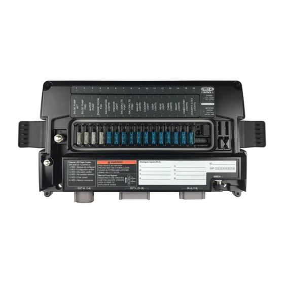
EN / CZone® Control 1 CONTROL 1 OVERVIEW Figure 1. Control 1 with Cover CONTROL 1 POWER Green - Available Red - Low Volts www.czone.net NETWORK STATUS Green - Power Red Flash - Traffic Channel LED Flash Codes WARNING Analogue Inputs (IN-A) -
Page 9: Led Indicators
EN / CZone® Control 1 LED INDICATORS CONTROL 1 POWER Green - Available Red - Low Volts www.czone.net NETWORK STATUS Green - Power Red Flash - Traffic Figure 3. LED Indicators 1. Circuit Status LED’s Colour Description Extinguished Channel Off... -
Page 10: Usb Port
EN / CZone® Control 1 USB PORT The USB port on the Control 1 allows system software updates and configuration files to be loaded from a USB Memory Stick. 3.5.1 General Requirements & Tips • Make sure the USB drive is FAT32 formatted. - Page 11 3. Wait for the USB LED to turn solid green before removing it, this operation can take 10-40minutes depending on the number of different module types in the system. The Control 1 channel LEDs will sweep back and forth when looking for devices of a particular type to update. Once devices of a particular type are found and are being updated, the LEDs will indicate progress for this update.
-
Page 12: System Example
EN / CZone® Control 1 SYSTEM EXAMPLE Figure 4. CZone Control 1 System Example... -
Page 13: Installation
Control 1 Module & Top Cover (included) • Deutsch Connector Kit (included with part # 80-911-0119-00) • 4 x 8G or 10G (4mm or 5mm) self-tapping screws or bolts for mounting Control 1 to surface • HDT-48-00 Deutsch crimp tool for crimping 0.5mm-4mm (20-12AWG) wire •... -
Page 14: Planning
• Make a list of all inputs and outputs to be wired to the Control 1 and take note of the output channel ratings and functions as shown in Figure 6. Ensure loads are wired to the appropriate channel for the functionality required. -
Page 15: Deutsch Connector Kit
EN / CZone® Control 1 DEUTSCH CONNECTOR KIT If you have purchased the Control 1 Deutsch connector kit (part # 80-911-0131-00), check all components are in the bag before proceeding. Image Part Number Description Quantity DEUTSCH DTP 4 POS MALE PLUG... -
Page 16: Mounting
1. Remove the Control 1 top cover and locate the 4 mounting screw locators as shown in Figure 9 2. Place the Control 1 on a solid, flat surface. 3. Screw the Control 1 to the surface with 4 x 8G or 10G (4mm or 5mm) self-tapping screws or bolts. CONNECTIONS... - Page 17 4. Insert the connector into the Control 1 and lock into place. 5. Load negatives are not connected to the Control 1, they must be connected to a common negative bus. Best wiring practice is to locate the negative connections close to the Control 1 so positive & negative wires run together minimizing magnetic fields.
- Page 18 2. The positive cable must be of sufficient size to carry the maximum current of all loads connected to the Control 1 and have a fuse/circuit breaker rated to protect the cable, volt drop should be kept to a minimum.
-
Page 19: Labels & Fuses
1. Using a marker pen, write the analogue and digital input names matching the input list and physical plug connections. 2. Write the Control 1 module number and location (i.e. Control 1 01 – Engine Room). This should match the module name in the configuration. -
Page 20: Set Dipswitch
8. Check the software version on the Control 1 with the CZone Configuration Tool and update if necessary. 9. Write configuration file to the Control 1 and the rest of the CZone modules on the system (Refer to the CZone Configuration Tool Instructions for details on how to configure the Control 1). -
Page 21: Specifications
IPx5 (mounted at 0°, +/-90°) Communication NMEA 2000 Weight 1.9kg Certification CE, ABYC, NMEA, ISO8846/SAEJ1171 Ignition Protected NMEA 2000 PGN’S NMEA 2000 PGN’s sent from the Control 1 PGN Number Description Fields 127508 Battery Status Battery Voltage 127505 Fluid Level... -
Page 22: Dimensions
EN / CZone® Control 1 DIMENSIONS 68 [2 11/16"] 339 [13 5/16"] 339 [13 3/8"] Figure 13. Control 1 Dimensions... - Page 23 EN / CZone® Control 1 6 ORDERING INFORMATION Control 1 Part Numbers and Accessories Part Number Description 80-911-0122-00 CZONE CONTROL 1 INTERFACE 80-911-0131-00 CZONE COI/CONTROL 1 DEUTSCH CONNECTOR KIT 80-911-0133-00 DEUTSCH CRIMP TOOL HDT-48-00...
Need help?
Do you have a question about the Control 1 and is the answer not in the manual?
Questions and answers