Table of Contents
Advertisement
Operation/Repair/Parts
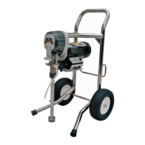
Airless Paint Sprayer
For portable spray application of architectural paints and coatings. For professional use
only.
Airlessco Home Depot LP540 Hi Boy (331861) Series B
3000 psi (20.7 MPa, 207 bar) Maximum Working Pressure
IMPORTANT SAFETY INSTRUCTIONS
Read all warnings and instructions in this manual. Be
familiar with the controls and the proper usage of the
equipment. Save these instructions.
3172585
Certified to CAN/CSA C22. No. 68
Conforms to UL 1450
3A1190H
EN
ti16047a
Advertisement
Table of Contents

Related Manuals for AIRLESSCO LP540 Hi Boy B Series


Summary of Contents for AIRLESSCO LP540 Hi Boy B Series
- Page 1 Airless Paint Sprayer For portable spray application of architectural paints and coatings. For professional use only. Airlessco Home Depot LP540 Hi Boy (331861) Series B 3000 psi (20.7 MPa, 207 bar) Maximum Working Pressure IMPORTANT SAFETY INSTRUCTIONS Read all warnings and instructions in this manual. Be familiar with the controls and the proper usage of the equipment.
- Page 2 Warnings Warnings The following warnings are for the setup, use, grounding, maintenance, and repair of this equipment. The exclama tion point symbol alerts you to a general warning and the hazard symbols refer to procedure-specific risks. When these symbols appear in the body of this manual or warning labels, refer back to these Warnings. Product-specific hazard symbols and warnings not covered in this section may appear throughout the body of this manual where applicable.
- Page 3 Warnings WARNING WARNING WARNING FIRE AND EXPLOSION HAZARD Flammable fumes, such as solvent and paint fumes, in work area can ignite or explode. To help prevent fire and explosion: • Do not spray or clean with materials having flash points lower than 100° F (38° C). Use only non-flam mable or water-based materials, or non-flammable paint thinners.
- Page 4 Warnings WARNING WARNING WARNING SKIN INJECTION HAZARD High-pressure spray is able to inject toxins into the body and cause serious bodily injury. In the event that injection occurs, get immediate surgical treatment. • Do not aim the gun at, or spray any person or animal. •...
- Page 5 Warnings WARNING WARNING WARNING MOVING PARTS HAZARD Moving parts can pinch, cut or amputate fingers and other body parts. • Keep clear of moving parts. • Do not operate equipment with protective guards or covers removed. • Pressurized equipment can start without warning. Before checking, moving, or servicing equipment, follow the Pressure Relief Procedure and disconnect all power sources.
-
Page 6: Component Identification
Component Identification Component Identification ti17301a Power switch Turns sprayer ON and OFF Pressure Control Knob Adjusts pressure. Turn clockwise to increase pressure and coun terclockwise to decrease pressure. Prime/Pressure Relief Valve Primes pump and relieves pressure from gun, hose and tip. Prime/Pressure Relief Valve Open Posi Relieves pressure from gun, hose and tip and primes the unit tion... -
Page 7: Operation
Operation Operation Pressure Relief Procedure 5. Re-engage gun trigger lock and close Prime/Pres sure Relief Valve.Turn Prime/Pressure Relief Valve to the open (priming) position to relieve residual pressure. Follow this Pressure Relief Procedure whenever you stop spraying and before cleaning, checking, servicing, or transporting equipment. -
Page 8: Prime And Flush Storage Fluid
Operation Flushing Fill the Packing Nut/Wet Cup 1. Fill the Packing Nut/Wet Cup with 5 drops of Air lessco Throat Seal Oil (TSO). • To reduce the risk of static sparking, which can cause fire or explosion. ti16049a • Always hold a metal part of the gun firmly against the metal pail when flushing. - Page 9 Operation 5. Open the prime/pressure relief valve to the open - 13. Whenever shutting down the sprayer, follow Pres “Priming Position”. This will allow an easy start. sure Relief Procedure, page 7. Open (Priming and Pressure NOTICE Closed Relief) (Pressure) To prevent damage and freezing during storage, never leave water in the fluid pump Startup...
-
Page 10: Adjusting The Pressure
Airlessco Pump spray tip when cleaning or checking for a cleared Conditioner. -
Page 11: Daily Maintenance
1. Keep the displacement pump packing nut/wet cup Pump Conditioner and water, a 50’ 1/4” airless hose, air lubricated with Airlessco TSO (Throat Seal Oil) at all less gun and tip on unit, open the prime/pressure relief times. The TSO helps protect the rod and packings. - Page 12 7. Tighten packing nut clockwise until resistance is felt against the Belleville Springs, go 3/4 of a turn more. Put five drops of Airlessco Throat Seal Oil in the packing nut. 8. Run the machine at full pressure for several min utes.
-
Page 13: Servicing The Inlet Valve
Maintenance Servicing the Inlet Valve 4. Now push the packing removal tool up through the pump and remove from the top bringing packings, spacer and springs along with it, leaving fluid body 1. Un-thread and remove suction nut from the fluid empty. -
Page 14: Gear And Pump Assembly
Maintenance 10. Take three upper polyethylene packings (18) and 18. Reinstall Fluid Pump, page 12. two leather packings (22) and assemble with inverted side down, on to the male gland (17) in the following order: • Polyethylene 2 2 2 •... -
Page 15: Replacement Of Electrical Components
Maintenance 6. If gear grease needs replacing, replace with gear NOTE: Ensure ground lead (A) is connected to bolt grease (Part No. 114819). below control board. 7. Clean mating surfaces of cover and box thoroughly. use Part No. 342899 Instant Gasket. 8. -
Page 16: On-Off Toggle Switch
Maintenance On-Off Toggle Switch Liquid Crystal Display (LCD) 1. Lower the pressure control assembly as described 1. Lower pressure control assembly as described above. above. 2. Disconnect the two wires on the toggle switch. 2. Unscrew the two nuts (M3) and remove LCD Dis play assembly. -
Page 17: Troubleshooting
Troubleshooting Troubleshooting General Problem Cause Solution Unit doesn’t prime Airleak due to loose suction nut Tighten suction nut. Airleak due to worn o-rings Replace o-ring (108526) on suction seat and o-ring (867370) below suction seat. Airleak due to hole in suction Replace suction hose. - Page 18 Troubleshooting Problem Cause Solution Motor Remove the motor brush covers and turn the machine ON. Set the potentiometer (POT) at maximum pressure and check for DC voltage across both brush terminals. It should read greater than 80 volts DC. If you have DC voltage, turn the machine off and unplug it from the wall.
-
Page 19: Pressure Control Repair
Troubleshooting Pressure Control Repair Motor Control Board Diagnostics Relieve pressure and unplug sprayer before servicing control board. See Pressure Relief Procedure, page 1. For sprayers with digital display, seeDigital Display Keep a new transducer on hand to use for test. Messages, page 20 NOTICE 2. - Page 20 Troubleshooting Digital Display Messages No display does not mean that sprayer is not pressur ized. Relieve pressure before repair. See Pressure Relief Procedure, page 7 DISPLAY SPRAYER OPERATION INDICATION ACTION No Display Sprayer stops. Power is not Loss of power. Check power source.
-
Page 21: Airless Spray Gun
Troubleshooting Airless Spray Gun Problem Cause Solution Coarse spray Low pressure Increase the pressure Excessive fogging (overspray) High pressure Reduce the pressure to satisfactory pattern distri bution. Material too thin Use less thinner Pattern too wide Spray angle too large Use smaller spray angle tip Pattern too narrow Spray angle too small... -
Page 22: Optional Manifold Filter
Parts Parts Optional Manifold Filter (866480) ti16052a Ref. Part Description Ref. Part Description 867145 COVER 867077 BASE 301356 SPRING 867420 PLUG 867377 O-RING 867309 NIPPLE 3/8”M x 1/4”M 867214 FILTER 60 MESH 557391 PLUG 1/4” 867647 SUPPORT 3A1190H... -
Page 23: Inlet Valve
Parts Inlet Valve Ref. Part Description 331011 FLUID PUMP BODY 331029 SUCTION BALL GUIDE 331030 SUCTION BALL 108526 O-RING 331292 SUCTION SEAT (HI-BOY) 331034 SUCTION NUT ti16055a Piston Assembly (331093) Ref. Part Description PISTON OUTLET BALL O-RING OUTLET SEAT OUTLET SEAT RETAINER PIN, SPRING COILED ti17684a 3A1190H... - Page 24 Parts Frame Parts Diagram ti17483a Ref. Part Description Ref. Part Description 331491 MOTOR,1HP, 90 VDC, 2500RPM 143029 COLLAR,SCREW,SET 331273 FRAME,LP540 HD 331048 BOOT,RUBBER BOOT 16F551 FASTENER,THREAD,EXTERNAL 342446 LABEL CLEANING-WARNING 866356 SPACER,SPACER .75 LG PVC 865674 HOSE,PAINT HOSE 1/4X50’ 106062 WHEEL,SEMI PNEUMATIC 24E513 GUN,SPRAY, 009 (HOME DEPOT) 3A1190H...
-
Page 25: Control Parts Diagram
Parts Control Parts Diagram ti17482a Ref. Part Description Ref. Part Description 867800 TERMINAL BOX WELDMENT 342513 LABEL OFF-ON 117281 SPACER,#6 X .312 HEAT SINK,MACHINED LP 867816 SCREW,MACH,PHILLIPS FLAT SCREW,MACH,PHILLIPS PAN HD SPACER,CONTROL BOARD 867821 DISPLAY,LCD CONNECTOR,ELECTRICAL 867731 WASHER,PLAIN-1/8IN.IDX5/16IN. MOTOR 867812 MOTOR CONNECTOR 867817 NUT,HEX GUARD,SPLASH 256219 POTENTIOMETR,ASSEMBLY... -
Page 26: Motor And Drive Parts Diagram
Parts Motor and Drive Parts Diagram ti17481c 3A1190H... - Page 27 Parts Motor and Drive Parts List Ref. Part Description Ref. Part Description 866428 PRESSURE RELIEF VALVE 331491 MOTOR,1HP, 90 VDC, 2500RPM 331336 HOOK,PAIL 867243 GASKET,SEAL 113783 SCREW,MACH,PNH 867800 BOX,TERMINAL BOX WELDMENT 331029 RETAINER,PUMP 15V909 SCREW,M8X12 331030 BALL,BALL .500 GR100 ...SS 440 867813 MANIFOLD, 866479...
-
Page 28: Packing Replacement
Parts Packing Replacement 2* 2* 2* ti16057a 3A1190H... - Page 29 Parts Packing Replacement Ref. Part Description 331014 MALE GLAND 331016 PACKING POLYETHYLENE 2 2 2 331308 FEMALE ADAPTOR 331011 FLUID PUMP BODY 331029 SUCTION BALL GUIDE 331030 SUCTION BALL 108526 O-RING 331292 SUCTION SEAT (HI-BOY) 331034 SUCTION NUT 1 2 2 2 331314 OUTLET SEAT RETAINER 331026 OUTLET SEAT 12+* 111457 O-RING...
-
Page 30: Suction Assemblies
Parts Gearbox Sleeve Bearing Replacement Ref. Part Description 331061 SLEEVE BEARING 331103 WASHER 331197 SCREW When replacing item (1), cover outside of sleeve with 6 drops of Loctite 246 prior to inserting into cover assembly. ti16059a Suction Assemblies Standard Suction Assembly (331284) Optional Suction Assembly (865717) ti16061a ti16062a... -
Page 31: Electrical System
Parts Electrical System Black ON/OFF Black Switch Power Plug Black White Green Black (+) Black (-) from Motor ti2471b 2 x Red Ref.Part Description Ref. Part Description 331163 ELECTRICAL CORD110V 243222 KIT, REPAIR, TRANSDUCER 1 301083 TOGGLE SWITCH 256219 POTENTIOMETER PRESSURE CONTROL ASSEMBLY 110V 1 15H085 LABEL, Warning ... -
Page 32: Electrical Components
Parts Electrical Components ti16066a Ref. Part Description Ref. Part Description 867816 SCREW 867817 867804 LABEL, PRESSURE CONTROL LCD DISPLAY (PSI) 867798 WINDOW 867731 WASHER 117281 SPACER 867821 LCD DISPLAY Kit (PSI) Includes 1, 3, 4, 5, 6, 7 3A1190H... - Page 33 Stir paint and if necessary strain paint using a paint strainer bag to remove lumps. ti16068a STEP 2 Check gun/hose connections to make sure they are tight. Lock gun trigger lock (Airlessco gun shown). Plug into 3 pronged grounded electrical outlet. Extension cord must be 3 wire, 12 gauge. Do not coil cord. ti16069a STEP 3 Put pump suction tube into bucket of paint.
- Page 34 Parts Cleaning • Always use low pressure in the cleaning process. • Always remove spray tip before cleaning - AFTER following the Pressure Relief Procedure! • Use a metal bucket for cleaning and maintain firm metal to metal contact to gun to the bucket. Tools and Equipment Needed Soft bristle brush, clean-up rags.
-
Page 35: Technical Data
Technical Data Technical Data Airless Paint Sprayer Metric Maximum working pressure 3000 psi 21 MPa, 207 bar Power requirements 120V AC, 60 hz, 11A, 1 phase Generator required 3000 w minimum Maximum delivery 0.57 gpm 2.2 lpm Maximum tip size 0.025 Fluid outlet npsm 1/4 in. -
Page 36: Airlessco Standard Warranty
With the exception of any special, extended, or limited warranty published by Airlessco, Airlessco will, for a period of twelve months from the date of sale, repair or replace any part of the equipment determined by Airlessco to be defective.
Need help?
Do you have a question about the LP540 Hi Boy B Series and is the answer not in the manual?
Questions and answers