Waters Xevo TQ MS Operator's, Overview And Maintenance Manual
Hide thumbs
Also See for Xevo TQ MS:
- Operator and maintenance manual (184 pages) ,
- Quick start manual (2 pages)

Subscribe to Our Youtube Channel
Related Manuals for Waters Xevo TQ MS


Summary of Contents for Waters Xevo TQ MS
- Page 1 Waters Xevo TQ MS Operator’s Overview and Maintenance Guide 71500130002 / Revision D Copyright © Waters Corporation 2013. All rights reserved...
- Page 2 February 11, 2013, 71500130002 Rev. D...
-
Page 3: General Information
Corporation assumes no responsibility for any errors that may appear in this document. This document is believed to be complete and accurate at the time of publication. In no event shall Waters Corporation be liable for incidental or consequential damages in connection with, or arising from, its use. For the most recent revision of this document, consult the Waters Web site (waters.com). -
Page 4: Customer Comments
Contacting Waters ® Contact Waters with enhancement requests or technical questions regarding the use, transportation, removal, or disposal of any Waters product. You can reach us via the Internet, telephone, or conventional mail. Waters contact information: Contacting medium Information... -
Page 5: Safety Considerations
Considerations specific to the Xevo TQ MS Solvent leakage hazard The source exhaust system is designed to be robust and leak-tight. Waters recommends you perform a hazard analysis, assuming a maximum leak into the laboratory atmosphere of 10% LC eluate. - Page 6 High temperature hazard To avoid burn injuries, avoid touching the source ion block Warning: assembly when operating or servicing the instrument. Xevo TQ MS high temperature hazard: Source ion block assembly TP03127 February 11, 2013, 71500130002 Rev. D...
- Page 7 The need to decontaminate other vacuum areas of the instrument depends on the kinds of samples the instrument analyzed and their levels of concentration. Do not dispose of the instrument or return it to Waters for repair until the authority responsible for approving its removal from the premises specifies the extent of decontamination required and the level of residual contamination permissible.
-
Page 8: Fcc Radiation Emissions Notice
FCC radiation emissions notice Changes or modifications not expressly approved by the party responsible for compliance, could void the users authority to operate the equipment. This device complies with Part 15 of the FCC Rules. Operation is subject to the following two conditions: (1) this device may not cause harmful interference, and (2) this device must accept any interference received, including interference that may cause undesired operation. -
Page 9: Operating This Instrument
United States and Canadian safety requirements Consult instructions for use Contact Waters Corporation for the correct disposal and recycling instructions Audience and purpose This guide is for operators of varying levels of experience. It gives an overview of the instrument, and explains how to prepare it, change its modes of operation, and maintain it. -
Page 10: Intended Use Of The Xevo Tq Ms
When analyzing samples from a complex matrix such as soil, tissue, serum/plasma, whole blood, and other sources, note that the matrix components can adversely affect LC/MS results, enhancing or suppressing ionization. To minimize these matrix effects, Waters recommends you adopt the following measures: •... -
Page 11: Ism Classification
Class A products are suitable for use in commercial (that is, nonresidential) locations and can be directly connected to a low voltage, power-supply network. EC authorized representative Waters Corporation (Micromass UK Ltd.) Floats Road Wythenshawe Manchester M23 9LZ United Kingdom... - Page 12 February 11, 2013, 71500130002 Rev. D...
-
Page 13: Table Of Contents
1 Waters Xevo TQ MS Overview .............. 21 Waters Xevo TQ MS ................... 22 ACQUITY Xevo TQ MS UPLC/MS systems............. 24 Non-ACQUITY devices for use with the Xevo TQ MS ........25 Software and data system ................. 26 February 11, 2013, 71500130002 Rev. D... - Page 14 Ionization techniques and source probes ............ 27 Electrospray ionization (ESI) ................27 Combined electrospray ionization and atmospheric pressure chemical ionization (ESCi) ....................27 Atmospheric pressure chemical ionization (APCI) .......... 27 Dual-mode APPI/APCI source................28 NanoFlow ESI source ..................28 IntelliStart Fluidics system ................29 Overview......................
- Page 15 Rebooting the mass spectrometer ..............49 Leaving the mass spectrometer ready for operation ........ 50 Emergency shutdown of the mass spectrometer ........50 3 Changing the Mode of Operation ............51 ESI mode ......................52 Installing the ESI probe ..................52 Removing the ESI probe..................
- Page 16 4 Maintenance Procedures ..............79 Maintenance schedule ..................81 Spare parts ......................82 Troubleshooting with Connections INSIGHT ..........83 Safety and handling ..................84 Preparing the instrument for working on the source ......85 Removing and refitting the source enclosure ..........87 Removing the source enclosure from the instrument ........
- Page 17 Fitting the sampling cone assembly to the source ......... 118 Cleaning the extraction cone ................ 120 Removing the ion block assembly from the source assembly ......120 Removing the extraction cone from the ion block .......... 122 Cleaning the extraction cone................124 Fitting the extraction cone to the ion block............
- Page 18 Warning symbols ....................196 Specific warnings ..................... 197 Caution advisory ....................200 Warnings that apply to all Waters instruments and devices ....201 Warnings that address the replacing of fuses ........... 206 Electrical and handling symbols ..............208 Electrical symbols .................... 208 Handling symbols ....................
- Page 19 Connecting the Edwards oil-free roughing pump ........223 Making the electrical connections for the Edwards oil-free roughing pump 228 Connecting to the nitrogen gas supply ............229 Connecting to the collision cell gas supply ..........230 Connecting the nitrogen exhaust line ............231 Connecting the liquid waste line ..............
- Page 20 February 11, 2013, 71500130002 Rev. D...
-
Page 21: Waters Xevo Tq Ms Overview
Waters Xevo TQ MS Overview This chapter describes the instrument, including its controls and connections for gas and plumbing. Contents: Topic Page Waters Xevo TQ MS................. 22 Ionization techniques and source probes ........27 IntelliStart Fluidics system............. 29 Ion optics ..................31 MS operating modes ................ -
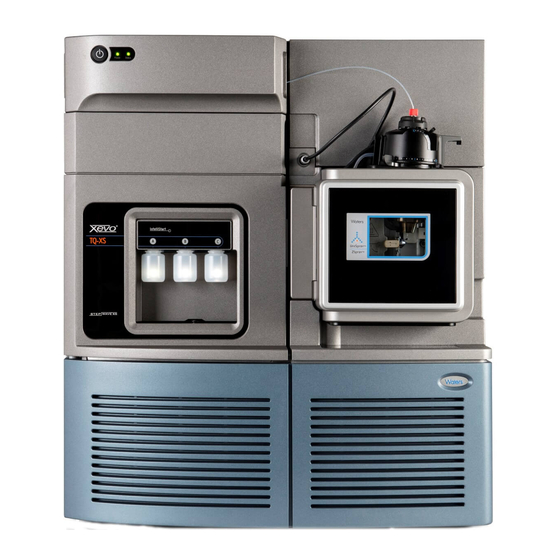
Page 22: Waters Xevo Tq Ms
/MS/MS analyses in quantitative and qualitative applications, it can ® operate at fast acquisition speeds compatible with UltraPerformance LC You can use the Xevo TQ MS with the following high-performance ZSpray™ dual-orthogonal API sources: • Standard multi-mode electrospray ionization/atmospheric pressure chemical ionization/combined electrospray ionization and atmospheric ®... - Page 23 Waters Xevo TQ MS Waters Xevo TQ MS: IntelliStart technology IntelliStart™ technology monitors LC/MS/MS performance and reports when the mass spectrometer is ready for use. The software automatically tunes and mass calibrates the mass spectrometer, displays performance readbacks, and enables simplified setup of the system for use in routine analytical and open access applications.
-
Page 24: Acquity Xevo Tq Ms Uplc/Ms Systems
1 Waters Xevo TQ MS Overview ACQUITY Xevo TQ MS UPLC/MS systems ® The Waters Xevo TQ MS is compatible with the ACQUITY UPLC systems; if you are not using an ACQUITY UPLC system, refer to the documentation relevant to your LC system. See “Non-ACQUITY devices for use with the Xevo... -
Page 25: Non-Acquity Devices For Use With The Xevo Tq Ms
UPLC Xevo TQ MS UPLC/MS system Similar to the ACQUITY UPLC system, the nanoACQUITY uses the optional NanoFlow source on the Xevo TQ MS. It is designed for capillary-to-nano-scale separations. Its sensitivity, resolution, and reproducibility well suit it for biomarker discovery and proteomics applications, including protein identification and characterization. -
Page 26: Software And Data System
1 Waters Xevo TQ MS Overview Software and data system MassLynx v4.1 or UNIFI software can control the mass spectrometer. See page 26 for more information about those applications. Both MassLynx and UNIFI software enable these major operations: • Configuring the instrument. -
Page 27: Ionization Techniques And Source Probes
Ionization techniques and source probes Available source options can vary depending on the software used to Note: operate the Xevo TQ MS. Refer to the MassLynx or UNIFI online Help for more information about supported sources. Electrospray ionization (ESI) In electrospray ionization (ESI), a strong electrical charge is applied to the eluent as it emerges from a nebulizer. -
Page 28: Dual-Mode Appi/Apci Source
1 Waters Xevo TQ MS Overview Dual-mode APPI/APCI source The optional, combined atmospheric pressure photoionization/atmospheric pressure chemical ionization (APPI/APCI) source comprises an APCI probe and the APPI lamp drive assembly. The APPI lamp drive assembly, which itself comprises a UV lamp and a repeller electrode. In addition, a specially-shaped, dual, APPI/APCI corona pin can be used. -
Page 29: Intellistart Fluidics System
IntelliStart Fluidics system IntelliStart Fluidics system Overview The IntelliStart Fluidics system is a solvent delivery system built into the mass spectrometer. It delivers sample directly to the MS probe in one of three ways: • From the LC column. • From three integral reservoirs. -
Page 30: System Components
1 Waters Xevo TQ MS Overview System components The onboard system incorporates a 6-port selector valve, a multi-position diverter valve, a pump, and three sample reservoirs. The sample reservoirs are mounted on the instrument’s front panel. When you select a solvent from the Instrument Console, a light-emitting diode (LED) illuminates the appropriate reservoir. -
Page 31: Ion Optics
Ion optics Ion optics The mass spectrometer’s ion optics operate as follows: Samples from the LC or instrument’s solvent delivery system are introduced at atmospheric pressure into the ionization source. The ions pass through the sample cone into the vacuum system. The ions pass through the transfer optics to the first quadrupole where they can be filtered according to their mass-to-charge ratio (m/z). -
Page 32: Ms Operating Modes
1 Waters Xevo TQ MS Overview MS operating modes The following table shows the MS operating modes. MS operating modes: Operating mode Collision cell Pass all masses Resolving (scanning) Pass all masses Resolving (static) In MS mode, the instrument can acquire data at scan speeds up to 10,000 Da/s. -
Page 33: Ms/Ms Operating Modes
MS/MS operating modes MS/MS operating modes In SIR and MRM modes, neither quadrupole is scanned, so no spectrum Note: (intensity versus mass) is produced. The following table shows the MS/MS operating modes. MS/MS operating modes: Operating mode Collision cell Product Static (at Pass all masses Scanning... -
Page 34: Product (Daughter) Ion Mode
1 Waters Xevo TQ MS Overview Product (daughter) ion mode Product ion mode is the most commonly used MS/MS operating mode. You can specify an ion of interest for fragmentation in the collision cell, thus yielding structural information. Product ion mode:... -
Page 35: Multiple Reaction Monitoring Mode
MS/MS operating modes Typical application You typically use the precursor ion mode for structural elucidation—that is, to complement or confirm product scan data—by scanning for all the precursors of a common product ion. Multiple reaction monitoring mode Multiple reaction monitoring (MRM) mode is a highly selective MS/MS equivalent of SIR. -
Page 36: Constant Neutral Loss Mode
1 Waters Xevo TQ MS Overview Constant neutral loss mode Constant neutral loss mode detects the loss of a specific neutral fragment or functional group from an unspecified precursor(s). The scans of MS1 and MS2 are synchronized. When MS1 transmits a specific precursor ion, MS2 “looks”... -
Page 37: Scanwave Daughter Scan Mode
MS/MS operating modes ScanWave daughter scan mode This mode is very similar to conventional product ion mode in that you can specify an ion of interest for fragmentation in the collision cell, thus yielding structural information. However, in this ScanWave mode the cell accumulates ions (intact or fragments) and then releases them, according to their mass, in synchrony with the second quadrupole mass analyzer. -
Page 38: Leak Sensors
1 Waters Xevo TQ MS Overview Leak sensors Leak sensors in the drip trays of the Xevo TQ MS continuously monitor the instrument for leaks. A leak sensor stops system flow when its optical sensor detects about 1.5 mL of accumulated leaked liquid in its surrounding reservoir. -
Page 39: Rear Panel
Rear panel Rear panel The following figure shows the rear panel locations of the connectors used to operate the mass spectrometer with external devices. Mass spectrometer rear panel: Shielded Ethernet LA N External Connections 1 Service Bus EPC Com Port External Connections 2 Video Output OUT -... - Page 40 1 Waters Xevo TQ MS Overview February 11, 2013, 71500130002 Rev. D...
-
Page 41: Preparing The Mass Spectrometer For Operation
Preparing the Mass Spectrometer for Operation This chapter describes how to start and shut down the mass spectrometer. Contents Topic Page Starting the mass spectrometer ............42 Preparing the IntelliStart Fluidics system........47 Rebooting the mass spectrometer ........... 49 Leaving the mass spectrometer ready for operation...... 50 Emergency shutdown of the mass spectrometer ...... -
Page 42: Starting The Mass Spectrometer
2 Preparing the Mass Spectrometer for Operation Starting the mass spectrometer This instrument is compatible with the ACQUITY UPLC system; if you are not using an ACQUITY UPLC system, refer to the documentation relevant to the system you are using. See “Non-ACQUITY devices for use with the Xevo TQ MS”... - Page 43 Starting the mass spectrometer Press the power switch on the top, left-hand side of the mass spectrometer and ACQUITY instruments. Each system instrument “beeps” and runs a series of startup tests. Result: Allow 3 minutes for the embedded PC to initialize. An audible alert sounds when the PC is ready.
- Page 44 IntelliStart software displays corrective actions in the Instrument Console. UNIFI software: From the Xevo TQ MS console, in the Maintain pane, click Vacuum. On the status page, click Pump. After a 20-second delay, during which the turbopump is Tip: starting, the roughing pump starts.
-
Page 45: Verifying The Instrument's State Of Readiness
Starting the mass spectrometer Verifying the instrument’s state of readiness When the mass spectrometer is in good operating condition, the power and Operate LEDs show constant green. You can view any error messages in IntelliStart software (MassLynx), or UNIFI software. Monitoring the mass spectrometer LEDs Light-emitting diodes on the mass spectrometer indicate its operational status. -
Page 46: Running The Mass Spectrometer At High Flow Rates
Running the mass spectrometer at high flow rates The ACQUITY UPLC system runs at high flow rates. To optimize desolvation, and thus sensitivity, run the ACQUITY Xevo TQ MS system at appropriate gas flows and desolvation temperatures. IntelliStart software automatically sets these parameters when you enter a flow rate, according to the following table. -
Page 47: Preparing The Intellistart Fluidics System
Preparing the IntelliStart Fluidics system Preparing the IntelliStart Fluidics system For additional information, see “Connecting the liquid waste line” on page 234. To avoid accidental spillage damaging the instrument, do not Caution: store large volume solvent reservoirs on top of the instrument. Installing the reservoir bottles Use standard reservoir bottles (30 mL) for instrument setup and calibration. -
Page 48: Purging The Infusion Pump
2 Preparing the Mass Spectrometer for Operation To avoid becoming contaminated with biohazards or Warning: toxic compounds, always wear chemical-resistant, powder-free gloves while performing this procedure. To install the low-volume vials: If a standard reservoir bottle is fitted, remove it. Screw the low-volume adaptors into the manifold, and finger tighten them. -
Page 49: Rebooting The Mass Spectrometer
Rebooting the mass spectrometer Rebooting the mass spectrometer The reset button shuts down the electronics momentarily and causes the mass spectrometer to reboot. Reboot the mass spectrometer when either of these conditions applies: • The mass spectrometer software fails to initialize. •... -
Page 50: Leaving The Mass Spectrometer Ready For Operation
2 Preparing the Mass Spectrometer for Operation Leaving the mass spectrometer ready for operation Leave the mass spectrometer in Operate mode except in the following cases: • When performing routine maintenance • When changing the source • When leaving the mass spectrometer unused for a long period In these instances, put the mass spectrometer in Standby mode, see the online Help for details. -
Page 51: Changing The Mode Of Operation
Combined Atmospheric Pressure Photoionization (APPI)/APCI • NanoFlow ESI. Available source options can vary depending on the software used Note: to operate the Xevo TQ MS. Refer to the MassLynx or UNIFI online Help for more information about supported sources. Contents: Topic Page ESI mode .................. -
Page 52: Esi Mode
3 Changing the Mode of Operation ESI mode To run ESI, you must fit the ESI probe to the ESI/APCI/ESCi source enclosure. The following sections explain how to install and remove the ESI probe. Installing the ESI probe Required material Chemical-resistant, powder-free gloves To avoid personal contamination with biohazards or Warning:... - Page 53 ESI mode With the probe label facing you, carefully slide the ESI probe into the hole in the probe adjuster assembly. The probe location dowel must align with the location Requirement: hole of the probe adjuster assembly. ESI probe location dowel Location hole of the probe adjuster assembly TP03129...
- Page 54 3 Changing the Mode of Operation ESI probe, mounted on the source enclosure: Vernier probe adjuster ESI probe Probe locking ring ESI probe cable Vertical probe High voltage connector adjuster Source window Source enclosure release TP03128 To avoid nitrogen leakage, fully tighten the probe Caution: locking ring.
- Page 55 ESI mode diverter valve to the ESI probe. Doing so minimizes delays and dispersion. Tubing connection between the diverter valve and the ESI probe: Diverter valve Tubing connection ESI probe Probe adjuster assembly The other plumbing connections are omitted for clarity. Tip: To prevent damage to the tubing, ensure that it does Caution:...
-
Page 56: Removing The Esi Probe
3 Changing the Mode of Operation Removing the ESI probe Required material Chemical-resistant, powder-free gloves To avoid personal contamination with biohazards or Warning: toxic materials, and to avoid spreading contamination to uncontaminated surfaces, wear clean, chemical-resistant, powder-free gloves while performing this procedure. The LC system connections, ESI probe, and source can be contaminated. -
Page 57: Esci Mode
ESCi mode ESCi mode To run ESCi, you must fit an ESI probe and corona pin to the ESI/APCI/ESCi source enclosure. “Installing the ESI probe” on page “Installing the corona pin in the source” on page 90, and “Combined electrospray ionization and atmospheric pressure chemical ionization (ESCi)”... -
Page 58: Installing The Apci Probe
3 Changing the Mode of Operation Installing the APCI probe Chemical-resistant, powder-free gloves Required material: To avoid personal contamination with biohazards or Warning: toxic materials, and to avoid spreading contamination to uncontaminated surfaces, wear clean, chemical-resistant, powder-free gloves while performing this procedure. The LC system connections, APCI probe, and source can be contaminated. - Page 59 APCI mode Tighten the probe locking ring to secure the probe in place. APCI probe mounted on the source enclosure: APCI probe Probe locking ring Vernier probe adjuster Vertical probe adjuster Source window Source enclosure release TP03128 Open the access door to the fluidics valve (see the figure on page 24).
-
Page 60: Removing The Apci Probe
3 Changing the Mode of Operation Removing the APCI probe Required material Chemical-resistant, powder-free gloves To avoid personal contamination with biohazards or Warning: toxic materials, and to avoid spreading contamination to uncontaminated surfaces, wear clean, chemical-resistant, powder-free gloves while performing this procedure. The LC system connections, APCI probe, and source can be contaminated. -
Page 61: Combined Appi/Apci Source
Combined APPI/APCI source Combined APPI/APCI source This optional, replacement source-enclosure can be operated as APPI, APCI or dual-mode APPI/APCI. Where, dual-mode APPI/APCI performs rapid switching between ionization modes. APPI operation In atmospheric pressure photoionization (APPI) mode, the source is fitted with an APCI probe, and the APPI lamp drive assembly is advanced into the source. -
Page 62: Apci Operation
3 Changing the Mode of Operation APCI operation Atmospheric pressure chemical ionization (APCI) produces singly-charged protonated or deprotonated molecules for a large range of nonvolatile analytes. In APCI mode, the source is fitted with an APCI corona pin. Unused, the APPI lamp drive assembly is retracted from the source. APCI mode: APCI probe Sample cone... -
Page 63: Dual-Mode Operation
Combined APPI/APCI source Dual-mode operation Dual-mode operation enables rapid switching between APPI and APCI ionization modes and allows high-throughput operations (for example, for sample screening). You replace the standard corona pin with a specially shaped APPI/APCI corona pin, so that the APPI lamp holder can be advanced into the source for dual operation. -
Page 64: The Combined Appi/Apci Source Components
3 Changing the Mode of Operation The combined APPI/APCI source components The Combined APPI/APCI source comprises the standard APCI probe and a source enclosure with an APPI lamp drive incorporated. The combined APPI/APCI source enclosure: APPI lamp drive assembly XMS0001 To prevent damage to the corona pin and lamp Caution: assembly, ensure that the lamp assembly does not touch the... - Page 65 Combined APPI/APCI source APPI lamp drive assembly inside the source enclosure: APPI lamp drive assembly Source enclosure APCI probe UV lamp and repeller electrode TP03201 February 11, 2013, 71500130002 Rev. D...
-
Page 66: Installing The Combined Appi/Apci Source Software
3 Changing the Mode of Operation Installing the Combined APPI/APCI Source software If the Combined APPI/APCI Source is not installed on the instrument, insert the Software Upgrade CD-ROM into the MassLynx workstation CD drive, and follow the on-screen instructions. If this software upgrade is not installed, the APPI options will not be Tip: available in the Tune window’s Ion Mode menu. - Page 67 Combined APPI/APCI source Connect the APPI drive cable, to the instrument front panel. Connect the HT cable, to the instrument front panel. To prevent damage to the corona pin and lamp Caution: assembly, ensure that the lamp assembly does not touch the corona pin when the source enclosure door is closed.
-
Page 68: Removing The Apci Probe And Appi Source Enclosure
3 Changing the Mode of Operation Removing the APCI probe and APPI source enclosure Required materials Chemical-resistant, powder-free gloves To avoid personal contamination with biohazards or Warning: toxic materials, and to avoid spreading contamination to uncontaminated surfaces, wear clean, chemical-resistant, powder-free gloves while performing this procedure. -
Page 69: Nanoflow Esi Source
NanoFlow ESI source NanoFlow ESI source The NanoFlow source enclosure comprises the NanoFlow stage (for x-, y-, z-axis adjustment), the sprayer-enclosure, and a microscope camera. NanoFlow source, stage and microscope camera: Microscope camera Sprayer enclosure X, Y, Z stage XMS0022 A sprayer is mounted on an X, Y, Z stage (three-axis manipulator) which slides on a pair of guide rails that allow its withdrawal from the source-enclosure for maintenance and changes. -
Page 70: Installing The Nanoflow Source
3 Changing the Mode of Operation Installing the NanoFlow source Required materials • Chemical-resistant, powder-free gloves To avoid personal contamination with biohazards or Warning: toxic materials, and to avoid spreading contamination to uncontaminated surfaces, wear clean, chemical-resistant, powder-free gloves while performing this procedure. The source components can be contaminated. - Page 71 For details regarding how to fit each sprayer, see the corresponding Tip: reference: • Waters Universal NanoFlow Sprayer Installation and Maintenance Guide (part number 71500110107) • “Fitting a borosilicate glass capillary (nanovial)” on page 73 • Capillary Electrophoresis/ Capillary Electrochromatography Sprayer User's Guide (part number 6666522) February 11, 2013, 71500130002 Rev.
- Page 72 3 Changing the Mode of Operation Connect the probe cable to the instrument’s PROBE connection. The NanoFlow stage contains a high voltage interlock so that Note: unless the sprayer is pushed fully forward in the source, the capillary voltage (the voltage applied to the sprayer assembly) and the sampling cone voltage are disabled.
-
Page 73: Fitting A Borosilicate Glass Capillary (Nanovial)
NanoFlow ESI source Fitting a borosilicate glass capillary (nanovial) Required materials • Chemical-resistant, powder-free gloves • Needle-nose pliers To avoid lacerations, puncture injuries, and Warning: possible contamination with biohazardous and toxic samples, do not touch the sharp end of the capillary. To avoid damaging capillaries, take great care Caution: when handling them. - Page 74 3 Changing the Mode of Operation Unscrew the union from the end of the sprayer assembly. Capillary Union Remove the existing capillary from the sprayer. Carefully remove the new borosilicate glass capillary from its case by lifting vertically while pressing down on the foam with two fingers. Foam Capillary Load sample into the capillary using either a fused silica syringe needle...
- Page 75 NanoFlow ESI source When using a GELoader tip, break the glass Recommendation: capillary in half, scoring it with a fused silica cutter so that the GELoader can reach the capillary’s tip. Thread the knurled nut and approximately 5 mm of conductive elastomer over the blunt end of the capillary.
- Page 76 3 Changing the Mode of Operation 14. On the MassLynx MS Tune window, ensure that the Capillary (kV) parameter on the ES+/- Source tab is set to 0. To avoid damage to the capillary tip, adjust the sprayer Caution: tip position before you push the sprayer inside the NanoFlow source enclosure.
-
Page 77: Positioning The Borosilicate Glass Capillary Tip
NanoFlow ESI source Positioning the borosilicate glass capillary tip Once a signal is obtained, you must adjust the tip position to maximize the signal. Using the three-axis manipulator, you can adjust the tip position up and down, left and right, forwards and backwards. As a starting point, set the tip so that it is on the center line of the sampling cone and at a distance between two and three times the diameter of the cone aperture. - Page 78 3 Changing the Mode of Operation February 11, 2013, 71500130002 Rev. D...
-
Page 79: Maintenance Procedures
Maintenance Procedures This chapter provides the maintenance guidelines and procedures necessary to maintain the instrument’s performance. Keep to a maintenance schedule, and perform maintenance as required and described in this chapter. Contents Topic Page Maintenance schedule ..............81 Spare parts ..................82 Troubleshooting with Connections INSIGHT ........ - Page 80 4 Maintenance Procedures Contents (Continued) Topic Page Cleaning the APCI probe tip ............158 Replacing the APCI probe sample capillary ........159 Cleaning or replacing the corona pin ..........165 Replacing the APCI probe heater............ 166 Replacing the ion block source heater..........170 Replacing the source assembly seals ..........
-
Page 81: Maintenance Schedule
Maintenance schedule Maintenance schedule The following table lists periodic maintenance schedules that ensure optimum instrument performance. Maintenance schedule: Procedure Frequency For information... Clean the instrument case. As required. page Empty the nitrogen exhaust Check daily, empty as page trap bottle. required. -
Page 82: Spare Parts
Replace the APPI lamp drive Annually. page 185. assembly O-rings. Spare parts Replace only the parts mentioned in this document. For spare parts details, ® see the Waters Quality Parts Locator on the Waters Web site’s Services/Support page. February 11, 2013, 71500130002 Rev. D... -
Page 83: Troubleshooting With Connections Insight
Connections INSIGHT is an intelligent device management (IDM) Web service that enables Waters to provide proactive service and support for the ACQUITY UPLC system. To use Connections INSIGHT, a Waters technician must install its service agent software on your workstation. In a client/server system, the service agent must also be installed on the computer from which you control the system. -
Page 84: Safety And Handling
4 Maintenance Procedures Safety and handling Bear in mind the following safety considerations when performing maintenance procedures: To avoid personal contamination with biohazards or Warning: toxic materials, and to avoid spreading contamination to uncontaminated surfaces, wear clean, chemical-resistant, powder-free gloves while handling instrument components. To prevent injury, always observe Good Laboratory Warning: Practice when handling solvents, changing tubing, or operating... -
Page 85: Preparing The Instrument For Working On The Source
In the Instrument Console, click Stop Flow to stop the LC flow or. If column flow is required, divert the LC flow to waste: Note: In the Instrument Console system tree, expand Xevo TQ MS Detector, Interactive Fluidics. Click Control Select Waste as the flow state. - Page 86 4 Maintenance Procedures To use UNIFI software to prepare the instrument for working on the source: On the System Console tool bar, click Stop Flow to stop the LC flow. If column flow is required, divert the LC flow to waste: Note: On the Setup pane, click Fluidics.
-
Page 87: Removing And Refitting The Source Enclosure
Removing and refitting the source enclosure Removing and refitting the source enclosure The optional combined APPI/APCI and NanoFlow sources are supplied as a complete source enclosure. To fit them, you must first remove the standard source enclosure. Removing the source enclosure from the instrument Required materials Chemical-resistant, powder-free gloves To avoid personal contamination with biohazards or... - Page 88 4 Maintenance Procedures Using both hands, grasp the source enclosure, and lift it vertically off the two supporting studs on the source adaptor housing. Supporting stud TP03164 Source enclosure February 11, 2013, 71500130002 Rev. D...
-
Page 89: Fitting The Source Enclosure To The Instrument
Removing and refitting the source enclosure Fitting the source enclosure to the instrument Required materials Chemical-resistant, powder-free gloves To avoid personal contamination with biohazards or Warning: toxic materials, and to avoid spreading contamination to uncontaminated surfaces, wear clean, chemical-resistant, powder-free gloves while performing this procedure. The source components can be contaminated. -
Page 90: Installing And Removing The Corona Pin
4 Maintenance Procedures Installing and removing the corona pin For ESCi, APCI and dual-mode APCI/APPI operation, you must fit a corona pin. Installing the corona pin in the source Required materials Chemical-resistant, powder-free gloves To avoid personal contamination with biohazards or Warning: toxic materials, and to avoid spreading contamination to uncontaminated surfaces, wear clean, chemical-resistant,... - Page 91 Installing and removing the corona pin Remove the blanking plug from the corona pin mounting contact. Store the blanking plug in a safe location. Tip: Corona pin mounting contact: Corona pin mounting contact blanking plug TP03130 To avoid puncture wounds, handle the corona pin with Warning: care;...
- Page 92 4 Maintenance Procedures Look through the source window and use the vernier probe adjuster to position the ESI probe tip so that it is pointing approximately midway between the tips of the sample cone and corona pin. Vernier probe adjuster TP03128 February 11, 2013, 71500130002 Rev.
-
Page 93: Removing The Corona Pin From The Source
Installing and removing the corona pin Removing the corona pin from the source Required materials Chemical-resistant, powder-free gloves To avoid personal contamination with biohazards or Warning: toxic materials, and to avoid spreading contamination to uncontaminated surfaces, wear clean, chemical-resistant, powder-free gloves while performing this procedure. The LC system connections, ESI probe, and source can be contaminated. -
Page 94: Operating The Source Isolation Valve
4 Maintenance Procedures Operating the source isolation valve You must close the source isolation valve to isolate the source from the instrument vacuum system for certain maintenance procedures. Required materials Chemical-resistant, powder-free gloves To avoid personal contamination with biohazards or Warning: toxic materials, and to avoid spreading contamination to uncontaminated surfaces, wear clean, chemical-resistant,... - Page 95 Operating the source isolation valve Close the source isolation valve by moving its handle counterclockwise, to the vertical position. Isolation valve handle in closed position February 11, 2013, 71500130002 Rev. D...
- Page 96 4 Maintenance Procedures To avoid personal contamination with biohazards or Warning: toxic materials, and to avoid spreading contamination to uncontaminated surfaces, wear clean, chemical-resistant, powder-free gloves while performing this procedure. The source components can be contaminated. To avoid puncture wounds, take great care while Warning: working with the source enclosure open if one or both of these conditions apply:...
-
Page 97: Removing O-Rings And Seals
Removing O-rings and seals Removing O-rings and seals When performing certain maintenance procedures, you must remove O-rings or seals from instrument components. An O-ring removal kit is provided with the instrument. O-ring removal kit: Tool 1 Tool 2 To remove an O-ring: To avoid damage, be careful not to scratch components with Caution: the removal tool when removing an O-ring or seal. -
Page 98: Cleaning The Instrument Case
4 Maintenance Procedures Cleaning the instrument case To avoid damage, do not use abrasives or solvents to clean the Caution: instrument’s case. Use a soft cloth, dampened with water, to clean the outside surfaces of the mass spectrometer. Emptying the nitrogen exhaust trap bottle Inspect the nitrogen exhaust trap bottle in the instrument’s exhaust line, daily and empty it before it is more than approximately 10% full. - Page 99 Emptying the nitrogen exhaust trap bottle Required materials Chemical-resistant, powder-free gloves To empty the nitrogen exhaust trap bottle: To stop the LC flow, follow the action below for your software: Software Action MassLynx In the instrument console, click Stop Flow UNIFI On the System Console tool bar, click Stop Flow Pull the source enclosure release (located at the bottom, right-hand side)
- Page 100 4 Maintenance Procedures To start the LC flow, follow the action below for your software: Software Action MassLynx In the instrument console, click Start Flow UNIFI On the System Console tool bar, click Start Flow February 11, 2013, 71500130002 Rev. D...
-
Page 101: Inspecting The Varian Roughing Pump Oil Level
Inspecting the Varian roughing pump oil level Inspecting the Varian roughing pump oil level To ensure correct operation of the Varian™ roughing pump, Caution: do not operate the pump with the oil level at less than 30% of the MAX level. -
Page 102: Adding Oil To The Varian Roughing Pump
4 Maintenance Procedures Adding oil to the Varian roughing pump If the roughing pump oil level is found to be low, you must add oil to the roughing pump. See “Inspecting the Varian roughing pump oil level” on page 101. Varian roughing pump: Oil filler plug Oil level sight glass... - Page 103 Adding oil to the Varian roughing pump To add oil to the roughing pump: Vent and shut down the mass spectrometer (see the mass spectrometer’s online Help for details). Allow the oil to settle in the pump. To avoid personal contamination with biohazards Warning: or toxic materials, always wear chemical-resistant, powder-free gloves when adding or replacing pump oil.
-
Page 104: Replacing The Varian Roughing Pump Oil And Oil Mist Filter
4 Maintenance Procedures Replacing the Varian roughing pump oil and oil mist filter Change the roughing pump oil and oil mist filter annually. This procedure is not required for an Edwards oil-free roughing pump. Emptying the roughing pump oil Required materials •... - Page 105 Replacing the Varian roughing pump oil and oil mist filter Tip the pump toward the drain plug aperture and allow the oil to drain completely into the container. To avoid spreading contamination, dispose of Warning: roughing pump oil according to local environmental regulations.
-
Page 106: Replacing The Oil Mist Filter
4 Maintenance Procedures Replacing the oil mist filter Required materials • Chemical-resistant, powder-free gloves • 3-mm Allen wrench • New oil mist filter To avoid personal contamination with biohazards or Warning: toxic materials, always wear chemical-resistant, powder-free gloves when performing this procedure. The oil mist filter and canister components can be contaminated with analyte accumulated during normal operation. - Page 107 Replacing the Varian roughing pump oil and oil mist filter Oil mist canister cover Spring Oil mist filter O-ring Remove the spring and oil mist filter from the canister. To avoid spreading contamination, ensure that Warning: the oil mist filter is correctly disposed of according to local environmental regulations.The oil mist filter can be contaminated with biohazards or toxic materials.
-
Page 108: To Refill The Pump With Oil
4 Maintenance Procedures To refill the pump with oil Required materials • Chemical-resistant, powder-free gloves • 8-mm Allen wrench • Funnel • 1-L bottle of Varian GP45 oil Refilling the pump with oil: To avoid personal contamination with biohazards or Warning: toxic materials, always wear chemical-resistant, powder-free gloves when adding or replacing oil. - Page 109 Replacing the Varian roughing pump oil and oil mist filter Ensure that the O-ring on the oil filler plug is clean and properly seated. To avoid oil leakage when fitting the oil filler plug to Caution: the roughing pump, • ensure that the plug is not cross threaded. •...
-
Page 110: Cleaning The Source Components
4 Maintenance Procedures Cleaning the source components Clean the sample cone and cone gas nozzle when these conditions apply: • The sample cone and cone gas nozzle are visibly fouled. • LC and sample-related causes for decreased signal intensity have been dismissed. -
Page 111: Cleaning The Sampling Cone Assembly
Cleaning the sampling cone assembly Cleaning the sampling cone assembly You can remove the sampling cone assembly (comprising the sample cone, O-ring, and cone gas nozzle) for cleaning without venting the instrument. Removing the sampling cone assembly from the source Required materials Chemical-resistant, powder-free gloves To avoid personal contamination with biohazards or... - Page 112 4 Maintenance Procedures To remove the sampling cone assembly from the source: Close the source isolation valve (see “To close the source isolation valve before starting a maintenance procedure:” on page 94). Grasp the cone gas nozzle handle, and use it to rotate the sampling cone assembly 90 degrees, moving the handle from the vertical to the horizontal position.
-
Page 113: Disassembling The Sampling Cone Assembly
Cleaning the sampling cone assembly Disassembling the sampling cone assembly Required materials • Chemical-resistant, powder-free gloves • Combined 2.5-mm Allen wrench and cone extraction tool To avoid personal contamination with biohazards or Warning: toxic materials, and to avoid spreading contamination to uncontaminated surfaces, wear clean, chemical-resistant, powder-free gloves when working with the sampling cone assembly. - Page 114 4 Maintenance Procedures To avoid damaging the fragile sample cone, do not place Caution: it on its tip; instead, place it on its flanged base. Rotate and lift the tool and collar to remove the sample cone from the cone gas nozzle. Remove the O-ring from the sample cone.
-
Page 115: Cleaning The Sample Cone And Cone Gas Nozzle
Cleaning the sampling cone assembly Cleaning the sample cone and cone gas nozzle Required materials • Chemical-resistant, powder-free gloves. • Appropriately sized glass vessels in which to completely immerse components when cleaning. Use only glassware not previously cleaned with surfactants. •... - Page 116 4 Maintenance Procedures Place the vessels in the ultrasonic bath for 30 minutes. If you used formic acid in the cleaning solution, do as follows: Rinse the components by immersing them in separate glass vessels containing water and then placing the vessels in the ultrasonic bath for 20 minutes.
-
Page 117: Assembling The Sampling Cone Assembly
Cleaning the sampling cone assembly Assembling the sampling cone assembly Required materials Chemical-resistant, powder-free gloves Caution: • To avoid recontaminating the sampling cone assembly, wear clean chemical-resistant, powder-free gloves during this procedure. • To avoid damaging the fragile sample cone, do not place it on its tip; instead, place it on its flanged base. -
Page 118: Fitting The Sampling Cone Assembly To The Source
4 Maintenance Procedures Fitting the sampling cone assembly to the source Required material Chemical-resistant, powder-free gloves To avoid personal contamination with biohazards or Warning: toxic materials, and to avoid spreading contamination to uncontaminated surfaces, wear clean, chemical-resistant, powder-free gloves when working with the source components. To avoid puncture wounds, take great care while Warning: working with the source enclosure open if one or both of these... - Page 119 Cleaning the sampling cone assembly To fit the sampling cone assembly to the source: Ensure that the source isolation valve is in the closed position (see “To close the source isolation valve before starting a maintenance procedure:” on page 94). Hold the sampling cone assembly so that the cone gas nozzle handle is oriented horizontally and at the top, and then slide the sampling cone assembly into the ion block assembly.
-
Page 120: Cleaning The Extraction Cone
4 Maintenance Procedures Cleaning the extraction cone Clean the ion block and extraction cone when cleaning the sample cone and cone gas nozzle fails to increase signal sensitivity. You must remove the ion block assembly from the source assembly to clean the extraction cone. Removing the ion block assembly from the source assembly Required materials •... - Page 121 Cleaning the extraction cone Use the combined 2.5-mm Allen wrench and cone extraction tool to unscrew the 4 captive ion block assembly securing screws. Ion block assembly securing screws TP03130 Remove the ion block assembly from the PEEK ion block support. PEEK ion block support Ion block assembly...
-
Page 122: Removing The Extraction Cone From The Ion Block
4 Maintenance Procedures Removing the extraction cone from the ion block Required materials • Chemical-resistant, powder-free gloves • Combined 2.5-mm Allen wrench and cone extraction tool To avoid personal contamination with biohazards or Warning: toxic materials, and to avoid spreading contamination to uncontaminated surfaces, wear clean, chemical-resistant, powder-free gloves when working with the ion block components. - Page 123 Cleaning the extraction cone Caution: • To avoid damaging the extraction cone aperture, take great care when removing the extraction cone from the ion block. • To avoid damaging the fragile extraction cone, do not place it on its tip; instead, place it on its flanged base. Remove the extraction cone from the ion block.
-
Page 124: Cleaning The Extraction Cone
4 Maintenance Procedures Cleaning the extraction cone Required materials • Chemical-resistant, powder-free gloves. • Appropriately sized glass vessel in which to completely immerse the extraction cone when cleaning. Use only glassware not previously cleaned with surfactants. • HPLC-grade (or better) methanol. •... - Page 125 Cleaning the extraction cone If you used formic acid in the cleaning solution, do as follows: Rinse the extraction cone by immersing it in a glass vessel containing water and then placing the vessel in the ultrasonic bath for 20 minutes. Dry the components by immersing them in separate glass vessels containing methanol and then placing the vessels in the ultrasonic bath for 10 minutes.
-
Page 126: Fitting The Extraction Cone To The Ion Block
4 Maintenance Procedures Fitting the extraction cone to the ion block Required materials • Chemical-resistant, powder-free gloves • Combined 2.5-mm Allen wrench and cone extraction tool To avoid personal contamination with biohazards or Warning: toxic materials, and to avoid spreading contamination to uncontaminated surfaces, wear clean, chemical-resistant, powder-free gloves when working with the ion block. - Page 127 Cleaning the extraction cone To avoid recontaminating the ion block assembly, wear Caution: clean chemical-resistant, powder-free gloves during this procedure. To fit the ion block assembly to the source assembly: Fit the ion block assembly to the PEEK ion block support. Use the combined 2.5-mm Allen wrench and cone extraction tool to fit and then slowly tighten the 4 ion block assembly securing screws sequentially and in small increments.
-
Page 128: Cleaning The Ion Block Assembly
4 Maintenance Procedures Cleaning the ion block assembly Clean the ion block assembly if cleaning the sample cone, cone gas nozzle, and extraction cone fails to increase signal sensitivity. Disassembling the source ion block assembly Required materials • Chemical-resistant, powder-free gloves •... - Page 129 Cleaning the ion block assembly To avoid personal contamination with biohazards or Warning: toxic materials, and to avoid spreading contamination to uncontaminated surfaces, wear clean, chemical-resistant, powder-free gloves when working with the ion block assembly. To disassemble the ion block assembly: Remove the ion block assembly from the source assembly (see “Removing the ion block assembly from the source assembly”...
- Page 130 4 Maintenance Procedures Use the combined 2.5-mm Allen wrench and cone extraction tool to loosen the 2 ion block cover plate captive securing screws. Ion block cover plate securing screw Ion block cover plate Remove the ion block cover plate. Grasp the isolation valve and pull it out of the ion block.
- Page 131 Cleaning the ion block assembly Use the O-ring removal kit to carefully remove the isolation valve O-ring (see “Removing O-rings and seals” on page 97). To prevent spreading contamination, dispose of Warning: the isolation valve O-ring according to local environmental regulations.
- Page 132 4 Maintenance Procedures 12. Holding the PEEK ion block gently, use the needle-nose pliers to gently grasp the heat-shrink tubing on the heater cartridge assembly, and carefully slide it and the PEEK terminal block out of the ion block. Heat-shrink tubing PEEK terminal block Heater cartridge assembly 13.
- Page 133 Cleaning the ion block assembly 14. Use the O-ring removal kit to carefully remove the cone gas O-ring from the ion block. To avoid spreading contamination, dispose of the Warning: cover seal and cone gas O-ring according to local environmental regulations. They can be contaminated with biohazards or toxic materials.
- Page 134 4 Maintenance Procedures 18. Use the combined 2.5-mm Allen wrench and cone extraction tool to remove the captive screws securing the 2 PEEK extraction cone retainer clips. Securing screw Retainer clip Extraction cone Caution: • To avoid damaging the extraction cone aperture, take great care when removing the extraction cone from the ion block.
- Page 135 Cleaning the ion block assembly 20. Remove the extraction cone handle insulator from the extraction cone handle. 21. Remove the extraction cone seal from the ion block. Extraction cone seal February 11, 2013, 71500130002 Rev. D...
-
Page 136: Cleaning The Ion Block Components
4 Maintenance Procedures Cleaning the ion block components Required materials • Chemical-resistant, powder-free gloves. • Appropriately sized glass vessels in which to completely immerse components when cleaning. Use only glassware not previously cleaned with surfactants. • HPLC-grade (or better) methanol. •... - Page 137 Cleaning the ion block assembly If you used formic acid in the cleaning solution, do as follows: Rinse the components by immersing them separately in glass vessels containing water and then placing the vessels in the ultrasonic bath for 20 minutes. Dry the components by immersing them in separate glass vessels containing methanol and then placing the vessels in the ultrasonic bath for 10 minutes.
-
Page 138: Assembling The Source Ion Block Assembly
4 Maintenance Procedures Assembling the source ion block assembly Required materials • Chemical-resistant, powder-free gloves • Combined 2.5-mm Allen wrench and cone extraction tool • Needle-nose pliers • Isopropyl alcohol in small container Caution: • To avoid recontaminating the ion block assembly, wear clean chemical-resistant, powder-free gloves during this procedure. - Page 139 Cleaning the ion block assembly To avoid damaging the heater cartridge assembly wires, Caution: do not bend or twist them when fitting the assembly to the ion block. Using the needle-nose pliers to gently grasp the heat-shrink tubing on the heater cartridge assembly, slide the assembly and the PEEK terminal block into the ion block.
-
Page 140: Cleaning The Source Hexapole Assembly
4 Maintenance Procedures Cleaning the source hexapole assembly Clean the source hexapole assembly if cleaning the ion block, isolation valve, and extraction cone fails to increase signal sensitivity. Removing the ion block assembly, ion block support, and hexapole from the source assembly Required materials •... - Page 141 Cleaning the source hexapole assembly Use the 3-mm Allen wrench to unscrew and remove the 4 screws securing the PEEK ion block support to the adaptor housing. Adaptor housing PEEK ion block support Hexapole assembly Securing screws Remove the PEEK ion block support from the adaptor housing. Use the O-ring removal kit to carefully remove all the O-rings from the PEEK ion block support (see “Removing O-rings and seals”...
-
Page 142: Cleaning The Hexapole Assembly
4 Maintenance Procedures Cleaning the hexapole assembly Required materials • Chemical-resistant, powder-free gloves. • 500-mL measuring cylinder or appropriately sized glass vessel in which to completely immerse the hexapole when cleaning. Use only glassware not previously cleaned with surfactants. ® •... - Page 143 Cleaning the source hexapole assembly Hook Rear support ring TP02658 Add 1:1 methanol/water to the glass vessel until the hexapole assembly is immersed completely. Place the vessel in the ultrasonic bath for 30 minutes. To avoid recontaminating the hexapole assembly, wear Caution: clean, chemical-resistant, powder-free gloves for the rest of this procedure.
-
Page 144: Fitting The Hexapole Assembly, Peek Ion Block Support, And Ion Block Assembly To The Source Assembly
4 Maintenance Procedures Fitting the hexapole assembly, PEEK ion block support, and ion block assembly to the source assembly Required materials • Chemical-resistant, powder-free gloves • 3-mm Allen wrench • Lint-free cloth • HPLC-grade (or better) 1:1 methanol/water • New seals and O-rings To avoid recontaminating the source, wear clean, Caution: chemical-resistant, powder-free gloves during this procedure. - Page 145 Cleaning the source hexapole assembly Fit the PEEK ion block support to the instrument’s housing. To ensure correct operation of the instrument, the Caution: hexapole springs must not touch a hexapole rod. Use the 3-mm Allen wrench to fit and tighten the 4 PEEK ion block support securing screws.
-
Page 146: Replacing The Esi Probe Tip And Gasket
4 Maintenance Procedures Replacing the ESI probe tip and gasket Replace the ESI probe tip if a blockage occurs in the internal metal sheathing through which the stainless steel capillary passes or if the probe tip is damaged. Removing the ESI probe tip and gasket Required materials •... - Page 147 Replacing the ESI probe tip and gasket Use the 10-mm wrench to remove the probe tip. 10-mm wrench Probe tip If the probe tip is difficult to remove, use the 7-mm wrench in Tip: conjunction with the 10-mm wrench. 7-mm wrench 10-mm wrench Probe tip February 11, 2013, 71500130002 Rev.
- Page 148 4 Maintenance Procedures Remove the metal gasket from the probe tip. Metal gasket To avoid spreading contamination, dispose of the Warning: probe tip and metal gasket according to local environmental regulations. They can be contaminated with biohazards or toxic materials. Dispose of the metal gasket in accordance with local environmental regulations.
-
Page 149: Fitting The Esi Probe Tip And Gasket
Replacing the ESI probe tip and gasket Fitting the ESI probe tip and gasket Required materials • Chemical-resistant, powder-free gloves • 10-mm wrench To avoid personal contamination with biohazards Warning: or compounds that are toxic or corrosive, and to avoid spreading contamination to uncontaminated surfaces, wear clean, chemical-resistant, powder-free gloves when working with the probe and source components. -
Page 150: Replacing The Esi Probe Sample Capillary
4 Maintenance Procedures Replacing the ESI probe sample capillary Replace the stainless steel sample capillary in the ESI probe if it becomes blocked and cannot be cleared, or if it becomes contaminated or damaged. Removing the existing capillary Required materials •... - Page 151 Replacing the ESI probe sample capillary Use the combined 2.5-mm Allen wrench and cone extraction tool to remove the 3 probe end-cover retaining screws. End-cover retaining screws Remove the end-cover from the probe assembly. Nebulizer adjuster knob End-cover Unscrew and remove the nebulizer adjuster knob. February 11, 2013, 71500130002 Rev.
- Page 152 4 Maintenance Procedures Use the 10-mm wrench to remove the probe tip. 10-mm wrench Probe tip If the probe tip is difficult to remove, use the 7-mm wrench in Tip: conjunction with the 10-mm wrench. 7-mm wrench 10-mm wrench Probe tip February 11, 2013, 71500130002 Rev.
- Page 153 Replacing the ESI probe sample capillary Remove the metal gasket from the probe tip. Metal gasket Remove the PEEK union/UNF coupling assembly and capillary from the probe. PEEK union/UNF coupling assembly Capillary Unscrew and remove the knurled collar from the UNF coupling. PEEK union UNF coupling Locknut...
- Page 154 4 Maintenance Procedures 10. Use the 7-mm wrench to loosen the locknut. Use the 8-mm wrench, to steady the UNF coupling when loosening Tip: the locknut. 11. Unscrew the PEEK union from the UNF coupling (this connection is finger-tight only). Ferrule PTFE liner sleeve 12.
-
Page 155: Installing The New Capillary
Replacing the ESI probe sample capillary Installing the new capillary Required materials • Chemical-resistant, powder-free gloves • Combined 2.5-mm Allen wrench and cone extraction tool • 10-mm wrench • Needle-nose pliers • LC pump • HPLC-grade (or better) 1:1 acetonitrile/water •... - Page 156 4 Maintenance Procedures Probe inlet connector PEEK tubing TP02671 Fit the UNF coupling to the new capillary. Use the needle-nose pliers to slide a new liner sleeve and ferrule onto the capillary. Insert the capillary in the PEEK union, and ensure that it is fully seated. Screw the UNF coupling into the PEEK union, finger-tight only.
- Page 157 Replacing the ESI probe sample capillary 13. Remove the probe inlet connector and PEEK tubing from the PEEK union. 14. Carefully thread the capillary through the probe assembly. 15. Carefully push the PEEK union/UNF coupling assembly and capillary into the probe assembly so that the locating pin on the UNF coupling is fully engaged in the locating slot at the head of the probe assembly.
-
Page 158: Cleaning The Apci Probe Tip
See the mass spectrometer’s online Help for further details. To clean the APCI probe tip: On the Instrument Console system tree, click Xevo TQ MS > Manual optimization. On the manual optimization page, click to stop the liquid flow. -
Page 159: Replacing The Apci Probe Sample Capillary
Replacing the APCI probe sample capillary Replacing the APCI probe sample capillary Replace the stainless steel sample capillary in the APCI probe if it becomes blocked and you cannot clear it, or if it becomes contaminated or damaged. Removing the existing capillary Required materials •... - Page 160 4 Maintenance Procedures Remove the end-cover. Nebulizer adjuster knob End-cover Unscrew and remove the nebulizer adjuster knob. Remove the PEEK union/UNF coupling assembly and capillary from the probe. PEEK union/UNF coupling assembly Capillary Locknut Use the 7-mm wrench to loosen the locknut. February 11, 2013, 71500130002 Rev.
- Page 161 Replacing the APCI probe sample capillary Unscrew the PEEK union from the UNF coupling (this connection is finger-tight). Ferrule Remove the ferrule from the capillary. Remove the capillary from the UNF coupling. To avoid spreading contamination, dispose of the Warning: capillary and ferrule according to local environmental regulations.
-
Page 162: Installing The New Capillary
4 Maintenance Procedures Installing the new capillary Required materials • Chemical-resistant, powder-free gloves • Needle-nose pliers • 7-mm wrench • Combined 2.5-mm Allen wrench and cone extraction tool • Red, PEEK tubing • LC pump • HPLC-grade (or better) 1:1 acetonitrile/water •... - Page 163 Replacing the APCI probe sample capillary Probe inlet connector PEEK tubing TP02671 Fit the UNF coupling to the new capillary. Use the needle-nose pliers to slide a new ferrule onto the capillary. Insert the capillary in the PEEK union, and ensure that it is fully seated. Screw the UNF coupling into the PEEK union, finger-tight only.
- Page 164 4 Maintenance Procedures 13. Fit the PEEK union/UNF coupling assembly to the nebulizer adjuster knob. 14. Carefully thread the capillary through the probe assembly. 15. Carefully push the PEEK union/UNF coupling assembly and capillary into the probe assembly so that the locating pin on the UNF coupling is fully engaged in the locating slot at the head of the probe assembly.
-
Page 165: Cleaning Or Replacing The Corona Pin
Cleaning or replacing the corona pin Cleaning or replacing the corona pin Required materials • Chemical-resistant, powder-free gloves • Needle-nose pliers • HPLC-grade (or better) methanol • Lint-free tissue • Lapping film • Corona pin To avoid personal contamination with biologically Warning: hazardous, toxic, or corrosive materials, and to avoid spreading contamination to uncontaminated surfaces, wear... -
Page 166: Replacing The Apci Probe Heater
4 Maintenance Procedures Replacing the APCI probe heater Replace the APCI probe heater if it fails to heat. Removing the APCI probe heater Required materials • Chemical-resistant, powder-free gloves • Flat-blade, jeweler’s screwdriver To avoid personal contamination with biologically Warning: hazardous, toxic, or corrosive materials, and to avoid spreading contamination to uncontaminated surfaces, wear clean, chemical-resistant, powder-free gloves when working... - Page 167 Replacing the APCI probe heater To avoid damaging the probe heater’s electrical wiring, Caution: take great care when removing the probe heater cover or while the probe heater is exposed. Carefully pull the probe heater cover off the probe. Probe heater electrical wiring Probe heater February 11, 2013, 71500130002 Rev.
- Page 168 4 Maintenance Procedures Caution: • To avoid damaging the probe heater’s electrical wiring, take great care when gripping and handling the heater. • To avoid damaging the probe heater’s electrical connections, do not twist the heater when removing it from the probe assembly.
-
Page 169: Fitting The New Apci Probe Heater
Replacing the APCI probe heater Fitting the new APCI probe heater Required materials • Chemical-resistant, powder-free gloves • Flat-blade, jeweler’s screwdriver • APCI probe heater To fit the new APCI probe heater: Caution: • To avoid damaging the probe heater’s electrical wiring, take great care when gripping and handling the heater. -
Page 170: Replacing The Ion Block Source Heater
4 Maintenance Procedures Use the jeweler’s screwdriver to tighten the 2 set screws securing the probe heater cover to the probe. Fit the probe to the instrument (see “Installing the APCI probe” on page 58). In the Instrument Console, click API to start the desolvation gas. - Page 171 Replacing the ion block source heater Ensure that the isolation valve is closed. Isolation valve handle in closed position Use the combined 2.5-mm Allen wrench and cone extraction tool to loosen the 2 captive screws securing the ion block cover plate. Ion block cover plate securing screw Ion block cover plate Remove the ion block cover plate.
- Page 172 4 Maintenance Procedures Use the combined 2.5-mm Allen wrench and cone extraction tool to remove the 2 screws securing the heater wires to the PEEK terminal block. Heater cartridge wire securing screws PEEK terminal block Use the needle-nose pliers to carefully swing the ring terminal tags out of the terminal block.
- Page 173 Replacing the ion block source heater Use the needle-nose pliers to gently grasp the heat-shrink tubing on the heater cartridge assembly and slide the assembly out of the ion block. Heat-shrink tubing Heater cartridge assembly Dispose of the heater cartridge assembly. To avoid damaging the heater cartridge assembly Caution: wires, do not bend or twist them when fitting the assembly to the...
-
Page 174: Replacing The Source Assembly Seals
4 Maintenance Procedures Replacing the source assembly seals To avoid excessive leakage of solvent vapor into the Warning: laboratory atmosphere, the seals listed below must be renewed, at intervals of no greater than 1 year, exactly as described in this section. - Page 175 Replacing the source assembly seals To avoid personal contamination with biohazards Warning: or compounds that are toxic or corrosive, and to avoid spreading contamination to uncontaminated surfaces, wear clean, chemical-resistant, powder-free gloves when working with the source components. To remove the probe adjuster assembly probe and source enclosure seals: Remove the source enclosure from the instrument (see “Removing the source enclosure from the instrument”...
- Page 176 4 Maintenance Procedures Use the O-ring removal kit to carefully remove the following seals from the source enclosure: • Source enclosure seal • Nebulizer gas seal • Desolvation gas seal • Auxiliary gas seal Nebulizer gas seal Desolvation gas Auxiliary gas seal seal Source enclosure...
-
Page 177: Fitting The New Source Enclosure And Probe Adjuster Assembly Probe Seals
Replacing the source assembly seals Fitting the new source enclosure and probe adjuster assembly probe seals Required materials • Chemical-resistant, powder-free gloves • Wash bottle containing HPLC-grade (or better) 1:1 methanol/water • New seals To avoid personal contamination with biohazards Warning: or compounds that are toxic or corrosive, and to avoid spreading contamination to uncontaminated surfaces, wear... - Page 178 4 Maintenance Procedures These seals have a special cross-section; fit them in the Requirement: groove as shown. Seal Groove Fit the following new seals to the probe adjuster assembly: • Probe seal • Nebulizer gas seal Refit the source enclosure to the instrument (see “Fitting the source enclosure to the instrument”...
-
Page 179: Replacing The Air Filter
Replacing the air filter Replacing the air filter You must replace the air filter annually. Required materials • Needle-nose pliers • New filter To replace the air filter: Open the access door to the fluidics pump. Unscrew the captive thumbscrew on the filter cover. Thumbscrew Filter cover February 11, 2013, 71500130002 Rev. - Page 180 4 Maintenance Procedures Remove the filter cover from the instrument. Filter Filter cover Lift the filter, vertically, from the its slot in the instrument. If necessary, use the needle-nose files to grasp the filter. Tip: Dispose of the filter. Fit the new filter into the instrument. Fit the filter cover to the instrument.
-
Page 181: Appi/Apci Source-Changing The Uv Lamp Bulb
APPI/APCI source—changing the UV lamp bulb APPI/APCI source—changing the UV lamp bulb Required materials • Chemical-resistant, powder-free gloves • 2.5-mm Allen wrench ® • Small, Phillips (cross-head) screwdriver • 20-cm (8-inch) length of 4-mm nylon tube To avoid personal contamination with biologically Warning: hazardous, toxic, or corrosive materials, and to avoid spreading contamination to uncontaminated surfaces, wear... - Page 182 4 Maintenance Procedures Hook the short-end of the Allen wrench through the ring on the back of the bulb extraction plug, and tug to remove it. TP03202 Insert the length of 4-mm nylon tube through the back of the lamp drive assembly, and push the bulb forward.
- Page 183 APPI/APCI source—changing the UV lamp bulb To avoid breaking the bulb, do not use a screwdriver to Caution: push the bulb out of the lamp drive assembly. Pull the bulb out of the lamp drive assembly. Insert the new bulb into the lamp drive assembly. The lamp glass is magnesium fluoride.
-
Page 184: Appi/Apci Source-Cleaning The Lamp Window
4 Maintenance Procedures APPI/APCI source—Cleaning the lamp window The transmission of the high-energy photons responsible for APPI relies on the cleanliness of the magnesium fluoride lamp window. Clean the window to keep the surface clear of contamination, and thus avoid reduced sensitivity. Required materials •... -
Page 185: Appi/Apci Source-Replacing The Appi Lamp Drive Seals
APPI/APCI source—Replacing the APPI lamp drive seals APPI/APCI source—Replacing the APPI lamp drive seals To ensure the integrity of the source exhaust system, Warning: the APPI lamp drive assembly O-rings listed below must be renewed at intervals not exceeding one year, exactly as described in this section. - Page 186 4 Maintenance Procedures To avoid personal contamination with Warning: biologically hazardous, toxic, or corrosive materials, and to avoid spreading contamination to uncontaminated surfaces, wear clean, chemical-resistant, powder-free gloves when working with the probe and source components. To avoid electric shock, ensure that the Warning: instrument is in Standby mode before commencing this procedure.
- Page 187 APPI/APCI source—Replacing the APPI lamp drive seals Remove the 2 source enclosure, release-handle screws, and remove the handle. 4 source-enclosure cover screws lamp-drive cover screws (2) Release handle TP03204 Remove the remaining 2 screws, which are hidden by the release handle. Slide the cover off the lamp-drive.
- Page 188 4 Maintenance Procedures Take care not to drop the screws inside the lower cover. Tip: Lamp mounting flange Mounting-flange screw (4-off) TP03205 11. Slide the lamp assembly, shaft, and flange out of the APPI source enclosure. The cables remain attached to the shaft, which you fully withdraw Tip: and lay on the bench beside the source enclosure.
- Page 189 APPI/APCI source—Replacing the APPI lamp drive seals 12. Using the small, Phillips screwdriver, remove the electrode screw and repeller electrode. 13. Use the 2.5-mm Allen wrench to remove the two insulator screws. 14. Remove the PEEK insulator from the end of the mounting shaft. 15.
- Page 190 4 Maintenance Procedures 18. Use the O-ring removal kit to carefully remove the shaft mounting flange O-ring from the APPI source enclosure side (see “Removing O-rings and seals” on page 97). Lamp mounting flange O-ring XMS0016 To avoid spreading contamination, ensure that Warning: the O-rings are correctly disposed of according to local environmental regulations.
-
Page 191: Fitting The New Appi Lamp Drive Assembly O-Rings
APPI/APCI source—Replacing the APPI lamp drive seals Fitting the new APPI lamp drive assembly O-rings Required materials • Chemical-resistant, powder-free gloves • 2.5-mm Allen wrench • 1:1 methanol/water • Lint-free cloth To avoid personal contamination with Warning: biologically hazardous, toxic, or corrosive materials, and to avoid spreading contamination to uncontaminated surfaces, wear clean, chemical-resistant, powder-free gloves when working... - Page 192 4 Maintenance Procedures Fit the mounting shaft insertion tool to the mounting shaft. Mounting shaft insertion tool XMS0017 To prevent damage to the mounting shaft O-rings, fit Caution: the mounting shaft insertion tool to the mounting shaft before fitting the shaft to the lamp mounting flange. Slide the lamp mounting flange back over the shaft taking care to get the correct orientation.
- Page 193 APPI/APCI source—Replacing the APPI lamp drive seals 13. Use the small Phillips screwdriver to fit and tighten the repeller electrode retaining screw. 14. Insert the UV bulb into the lamp drive assembly and push it fully home. 15. Fully retract the lamp mounting shaft from the source enclosure. 16.
- Page 194 4 Maintenance Procedures February 11, 2013, 71500130002 Rev. D...
-
Page 195: A Safety Advisories
Page Warning symbols................196 Caution advisory ................200 Warnings that apply to all Waters instruments and devices ..201 Warnings that address the replacing of fuses ........ 206 Electrical and handling symbols ............. 208 February 11, 2013, 71500130002 Rev. D... -
Page 196: Warning Symbols
The following symbols warn of risks that can arise when you operate or maintain a Waters instrument or device, or a component of an instrument or device. When one of these symbols appear in a manual’s narrative sections or procedures, an accompanying statement identifies the applicable risk and explains how to avoid it. -
Page 197: Specific Warnings
Burst warning This warning applies to Waters instruments and devices fitted with nonmetallic tubing. To avoid injury from bursting, nonmetallic tubing, heed these Warning:... - Page 198 A Safety Advisories Mass spectrometer shock hazard The following warning applies to all Waters mass spectrometers. To avoid electric shock, do not remove the mass spectrometer’s Warning: protective panels. The components they cover are not user-serviceable. The following warning applies to certain mass spectrometers when they are in Operate mode.
- Page 199 Warning symbols Biohazard warning The following warning applies to Waters instruments and devices that can process material containing biohazards, which are substances that contain biological agents capable of producing harmful effects in humans. To avoid infection with potentially infectious, human-sourced...
-
Page 200: Caution Advisory
A Safety Advisories Caution advisory Caution advisories appear where an instrument or device can be subject to use or misuse that can damage it or compromise a sample’s integrity. The exclamation point symbol and its associated statement alert you to such risk. To avoid damaging the instrument’s case, do not clean it with Caution: abrasives or solvents. -
Page 201: Warnings That Apply To All Waters Instruments And Devices
Warnings that apply to all Waters instruments and devices Warnings that apply to all Waters instruments and devices When operating this device, follow standard quality-control procedures and the equipment guidelines in this section. Changes or modifications to this unit not expressly approved by the Attention: party responsible for compliance could void the user’s authority to operate the... - Page 202 A Safety Advisories Use caution when working with any polymer tubing under pressure: Warning: • Always wear eye protection when near pressurized polymer tubing. • Extinguish all nearby flames. • Do not use tubing that has been severely stressed or kinked. •...
- Page 203 Warnings that apply to all Waters instruments and devices fare attenzione quando si utilizzano tubi in materiale polimerico Attenzione: sotto pressione: • Indossare sempre occhiali da lavoro protettivi nei pressi di tubi di polimero pressurizzati. • Spegnere tutte le fiamme vive nell'ambiente circostante.
- Page 204 A Safety Advisories 警告:当有压力的情况下使用管线时,小心注意以下几点: • 当接近有压力的聚合物管线时一定要戴防护眼镜。 • 熄灭附近所有的火焰。 • 不要使用已经被压瘪或严重弯曲的管线。 • 不要在非金属管线中使用四氢呋喃或浓硝酸或浓硫酸。 • 要了解使用二氯甲烷及二甲基亚枫会导致非金属管线膨胀,大大降低管线的耐压能力。 경고: 가압 폴리머 튜브로 작업할 경우에는 주의하십시오. • 가압 폴리머 튜브 근처에서는 항상 보호 안경을 착용하십시오. • 근처의 화기를 모두 끄십시오. • 심하게 변형되거나 꼬인 튜브는 사용하지 마십시오. •...
- Page 205 Warnings that apply to all Waters instruments and devices The user shall be made aware that if the equipment is used in a Warning: manner not specified by the manufacturer, the protection provided by the equipment may be impaired. L’utilisateur doit être informé que si le matériel est utilisé d’une Attention: façon non spécifiée par le fabricant, la protection assurée par le matériel risque...
-
Page 206: Warnings That Address The Replacing Of Fuses
A Safety Advisories Warnings that address the replacing of fuses The following warnings pertain to instruments equipped with user-replaceable fuses. If the fuse types and ratings appear on the instrument: To protect against fire, replace fuses with those of the type Warning: and rating printed on panels adjacent to instrument fuse covers. - Page 207 Warnings that address the replacing of fuses If the fuse types and ratings do not appear on the instrument: To protect against fire, replace fuses with those of the type Warning: and rating indicated in the “Replacing fuses” section of the Maintenance Procedures chapter.
-
Page 208: Electrical And Handling Symbols
A Safety Advisories Electrical and handling symbols Electrical symbols The following electrical symbols and their associated statements can appear in instrument manuals and on an instrument’s front or rear panels. Electrical power on Electrical power off Standby Direct current Alternating current Protective conductor terminal Frame, or chassis, terminal Fuse... -
Page 209: Handling Symbols
Electrical and handling symbols Handling symbols The following handling symbols and their associated statements can appear on labels affixed to the packaging in which instruments, devices, and component parts are shipped. Keep upright! Keep dry! Fragile! Use no hooks! February 11, 2013, 71500130002 Rev. D... - Page 210 A Safety Advisories February 11, 2013, 71500130002 Rev. D...
-
Page 211: B Materials Of Construction And Compliant Solvents
Materials of Construction and Compliant Solvents To confirm the integrity of the source exhaust Warning: system, you must address any safety issues raised by the contents of this Appendix. Contents Topic Page Preventing contamination ............... 212 Items exposed to solvent..............212 Solvents used to prepare mobile phases ......... -
Page 212: Preventing Contamination
Preventing contamination For information on preventing contamination, refer to Controlling Contamination in LC/MS Systems (part number 715001307). Visit www.waters.com. Items exposed to solvent The items that appear in the following table can be exposed to solvent. You must evaluate the safety issues if the solvents used in your application differ from the solvents typically used with these items. -
Page 213: Solvents Used To Prepare Mobile Phases
Solvents used to prepare mobile phases Items exposed to solvent: (Continued) Item Material Trap bottle push-in fittings Nitrile butadiene rubber, stainless steel, polybutylene terephthalate, and polyoxymethylene APPI lamp drive assembly: Mounting shaft Stainless steel Repeller electrode Stainless steel Insulator PEEK Lamp window Magnesium fluoride Solvents used to prepare mobile phases... - Page 214 B Materials of Construction and Compliant Solvents February 11, 2013, 71500130002 Rev. D...
-
Page 215: C External Connections
To avoid damaging the mass spectrometer, observe the Caution: following precautions: • Contact Waters Technical Service before moving it. • If you must transport the instrument, or remove it from service, contact Waters Technical Service for recommended cleaning, flushing, and packaging procedures. -
Page 216: External Wiring And Vacuum Connections
C External Connections External wiring and vacuum connections The instrument’s rear panel connectors are shown below. Mass spectrometer rear panel connectors: Shielded Ethernet LA N External Connections 1 Service Bus EPC Com Port External Connections 2 Video Output OUT - Event inputs External Connections 1 External Connections 2... -
Page 217: Connecting The Varian Oil-Filled Roughing Pump
Connecting the Varian oil-filled roughing pump Connecting the Varian oil-filled roughing pump To connect the alternative, oil-free roughing pump, see “Connecting the Note: Edwards oil-free roughing pump” on page 223. Oil exhaust filter Electrical connection panel Inlet port flange TP03159 February 11, 2013, 71500130002 Rev. - Page 218 12.7-mm clear PVC exhaust tubing (included in the Waters Rotary Pump Kit) • PVC hose clamps (included in the Waters Rotary Pump Kit) • 1-inch ID vacuum hose (included in the Waters Rotary Pump Kit) • PTFE drip tray February 11, 2013, 71500130002 Rev. D...
- Page 219 Connecting the Varian oil-filled roughing pump Bear in mind these requirements when connecting the roughing pump: • The pump must be horizontal, or within one degree of horizontal. • The ambient temperature of the area in which you place the pump must range between 12 and 40 ºC (54 to 104 ºF).
- Page 220 C External Connections To connect the roughing pump: Place the PTFE drip tray on the floor, within 5 feet of the instrument. To avoid skeletal or muscle injury, at least two people Warning: must lift the pump. Place the pump on the PTFE drip tray. Attach the NW25 tee to the roughing pump inlet flange using an NW25 center ring, and then secure the connection with an NW25 clamp, using the 7-mm nut driver to install the clamp.
- Page 221 Connecting the Varian oil-filled roughing pump the connection with an NW25 clamp, using the 7-mm nut driver to install the clamp. Connect the free ends of the two lengths of vacuum hose to the two, 1-inch OD, straight, vacuum ports on the mass spectrometer’s rear panel.
-
Page 222: Making The Electrical Connections To The Varian Oil-Filled Roughing Pump
C External Connections Making the electrical connections to the Varian oil-filled roughing pump Roughing pump connections: LA N External Connections 1 Service Bus EPC Com Port External Connections 2 Video Output OUT - External Connections 1 External Connections 2 Auxiliary Roughing pump 10MB Activity... -
Page 223: Connecting The Edwards Oil-Free Roughing Pump
Connecting the Edwards oil-free roughing pump Connecting the Edwards oil-free roughing pump The oil-free roughing pump is an alternative to the oil-filled roughing pump. To connect the oil-filled roughing pump, see “Connecting the Varian oil-filled roughing pump” on page 217. Inlet flange Exhaust port flange TP03165... - Page 224 12.7-mm clear PVC exhaust tubing (included in the Waters Rotary Pump Kit) • PVC hose clamps (included in the Waters Rotary Pump Kit) • 1-inch ID vacuum hose (included in the Waters Rotary Pump Kit) February 11, 2013, 71500130002 Rev. D...
- Page 225 Connecting the Edwards oil-free roughing pump Bear in mind these requirements when connecting the roughing pump: • The pump must be horizontal, or within one degree of horizontal. • The ambient temperature of area in which you place the pump must range between 12 and 40 ºC (54 to 104 ºF).
- Page 226 C External Connections To avoid personal contamination with biohazards Warning: or toxic compounds, and to avoid spreading contamination to uncontaminated surfaces, wear clean, chemical-resistant, powder-free gloves when working with the pump and its connections. To avoid skeletal or muscle injury, at least two Warning: people must lift the pump.
- Page 227 Connecting the Edwards oil-free roughing pump Attach the elbow to one of the open ports on the NW25 tee using an NW25 center ring, and then secure the connection with an NW25 clamp, using the 7-mm nut driver to install the clamp. Attach the flanged end of a length of 1-inch ID vacuum hose to the remaining open port on the NW25 tee using an NW25 center ring, and then secure the connection with an NW25 clamp, using the 7-mm nut...
-
Page 228: Making The Electrical Connections For The Edwards Oil-Free Roughing Pump
C External Connections Making the electrical connections for the Edwards oil-free roughing pump Roughing pump connections: LA N External Connections 1 Service Bus EPC Com Port External Connections 2 Video Output OUT - External Connections 1 External Connections 2 Auxiliary Roughing pump 10MB Activity... -
Page 229: Connecting To The Nitrogen Gas Supply
Required materials • Chemical-resistant, powder-free gloves • 6-mm PTFE tubing (included in the Waters Rough Pump Connect Kit) • Nitrogen regulator To connect the nitrogen gas supply: Connect one end of the 6-mm PTFE tubing to the nitrogen inlet port on the rear of the instrument. -
Page 230: Connecting To The Collision Cell Gas Supply
C External Connections Connect the free end of the 6-mm PTFE tubing to the nitrogen regulator. The nitrogen must be dry and oil-free, with a purity of at Requirement: least 95%. Set the nitrogen regulator to 600 to 690 kPa (6.0 to 6.9 bar, 90 to 100 psi). -
Page 231: Connecting The Nitrogen Exhaust Line
Chemical-resistant, powder-free gloves • Sharp knife • Nitrogen exhaust trap bottle • 6-mm, 10-mm, and 12-mm PTFE tubing (included in the Waters Rough Pump Connect Kit) ® • snoop (or equivalent) leak detector liquid To avoid exposure to biohazards or toxic LC solvents... - Page 232 C External Connections To connect the nitrogen exhaust line: Locate the nitrogen exhaust trap bottle in an accessible area below the instrument. Nitrogen exhaust trap bottle: From instrument To laboratory pilot valve port exhaust port From instrument exhaust connection Nitrogen exhaust trap bottle TP03164 To avoid gas leaks, use the sharp knife to cut the PTFE...
- Page 233 Connecting the nitrogen exhaust line Cut a length of 12-mm tubing long enough to connect the instrument to the nitrogen exhaust trap bottle. Connect one end of the tubing to the exhaust port on the instrument’s rear panel. Connect the free end of the tubing to the inlet port on the nitrogen exhaust trap bottle.
-
Page 234: Connecting The Liquid Waste Line
C External Connections Connecting the liquid waste line Required materials • Chemical-resistant, powder-free gloves • Waste container To prevent personal contamination with biohazards or Warning: toxic materials, always wear chemical-resistant, powder-free gloves while performing this procedure. The waste line and connection can be contaminated. - Page 235 Connecting the liquid waste line To prevent leakage of biohazards or toxic Warning: materials, ensure that the, • drain line does not crimp or bend, impeding flow to the waste container; • waste container is emptied before the lower end of the drain tube is covered by waste solvent.
-
Page 236: Connecting The Workstation
C External Connections Connecting the workstation To avoid injury from electric shock or fire, and to Warning: prevent damage to the workstation and ancillary equipment, do not place objects filled with liquid—such as solvent bottles—on these items, or expose them to dripping or splashing liquids. -
Page 237: Connecting Ethernet Cables
Connecting Ethernet cables Connecting Ethernet cables Use shielded network cables with the mass spectrometer to Requirement: ensure compliance with FCC limits. To make Ethernet connections: Connect one end of one shielded Ethernet cable to the network switch, and then connect the other end to the Ethernet card on the ®... - Page 238 C External Connections Input and output connector locations: LA N External Connections 1 Service Bus External connections identification tables EPC Com Port External Connections 2 Video Output OUT - External connections 1 External Connections 1 External connections 2 External Connections 2 System Activity Input/output signal connector configuration: February 11, 2013, 71500130002 Rev.
- Page 239 Input/output signal connectors External connections 1: Function Rating Event In 1+, digital signal, optimum +3.3V +5 V max +5V Event In 1-, digital ground, 0V Not used Event In 2+, digital signal, optimum +3.3V +5 V max +5V Event In 2-, digital ground, 0V Not used Not used CE Interlock Out, common...
-
Page 240: Making Signal Connections
C External Connections Making signal connections Mass spectrometer signal connections: Signal connections Description Analog (Out) Used for analog chart output functionality. The output voltage range is 0 to 2 V. The resolution of the voltage output is 12 bits. Gas Fail Interlock Used to stop the solvent flow if the nitrogen gas (Out) supply fails. - Page 241 Input/output signal connectors Attach the positive and negative leads of the signal cable to the connector. Connector Signal cable TP02585 Slide the clamp (with the bend facing down) into the protective shield. Insert the clamp and shield (with the bend facing down) into the connection cover, and loosely tighten with one self-tapping screw.
- Page 242 C External Connections Insert the connector with the signal cable into the connection cover, and position the clamp over the cable leads, and tighten the clamp into place with the second self-tapping screw. Cable leads Clamp TP02587 Place the second connection cover over the first cover, and snap it into place.
-
Page 243: Connecting To The Electricity Source
For information regarding what cord to use in other countries, contact your local Waters distributor. To connect to the electricity source: Connect the female end of the power cord to the receptacle on the rear panel of the mass spectrometer. - Page 244 C External Connections February 11, 2013, 71500130002 Rev. D...
-
Page 245: D Plumbing The Intellistart Fluidics System
Plumbing the IntelliStart Fluidics System This appendix provides reference information for replacing the tubing in the IntelliStart™ Fluidics system. To avoid personal contamination with biohazards Warning: or toxic materials, always wear chemical-resistant, powder-free gloves while working on the IntelliStart Fluidics system. -
Page 246: Preventing Contamination
D Plumbing the IntelliStart Fluidics System Preventing contamination For information on preventing contamination, refer to Controlling Contamination in LC/MS Systems (part number 715001307). You can find this document on http://www.waters.com; click Services and Support > Support. Plumbing schematic Select valve... -
Page 247: Pipe Specifications
Pipe specifications Pipe specifications The following table gives the internal dimensions (ID), external dimensions (ED), Color, Length, and Quantity for the IntelliStart Fluidics pipes. Replacement pipe specifications: Connection ID (inches) ED (inches) Color Length (mm) Quantity Select to divert 0.005 1/16 Vial 0.020... - Page 248 D Plumbing the IntelliStart Fluidics System February 11, 2013, 71500130002 Rev. D...
Need help?
Do you have a question about the Xevo TQ MS and is the answer not in the manual?
Questions and answers