
Related Manuals for Durafly TUNDRA V2


Summary of Contents for Durafly TUNDRA V2
- Page 1 INSTRUCTION MANUAL VERSION Please read this manual carefully before operating this plane.
- Page 2 maintenance recommended exercise capable and responsible adult crowded...
-
Page 3: Table Of Contents
CONTENTS Introduction Specifications Content Required To Complete Model Optional Accessories Assembly (PNF) Setting Up Your Model 8-10 Tundra Options Floats 11-12 FPV Canopy Tow line mounting point Optional Candy Dropper Model Flying Precautions Pre-flight Checks Flying The Tundra Tundra Tips Spare Parts Listing Trouble Shooting V2 Updates... -
Page 4: Introduction
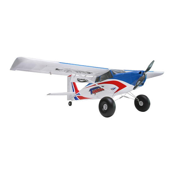
Introduction: Thank you for purchasing the Durafly Tundra V2. If you are looking for flying with no limits then you’ve found it with the Tundra! Whether it’s flying from rough bush fields, water, snow or sand, or FPV, aerobatics, glider towing, candy dropping or just good old fashioned super STOL slow flying, the Tundra takes on all with ease. -
Page 5: Content
6. Wing and tail spar Required To Complete Model: In its ‘Plug n Fly’ format the Tundra V2 will still require some additional electronic components to get it ‘flight ready’. Durafly recommends the products below for optimum performance and great value. Available at hobbyking.com... -
Page 6: Assembly (Pnf)
Assembly (PNF) 1. Out of the box your Tundra comes with reinforced foam hinges. However before assembly can begin, each hinge line must be flexed back and forth 5-6 times to reduce tension and load on the servo. Do this for all control surfaces before continuing. 2A. - Page 7 2B. Hook the supplied coil springs through the center ring of the spring support wire and the wire cross braces through the ring of the metal brace keepers (E) to complete the sprung cross bracing assembly (F). Now slide the main wheels onto the axle and secure in place with the plastic grip nut (G).
- Page 8 2x8mm 5. Using a pair of pliers (ball link pliers preferably) connect the elevator push rod to the elevator horn (A). To ensure both the elevator and rudder are neutral (with the servos centered) loosen the grub screw of the piano wire fastener and slide push rods until both surfaces are neutral if required (B). Tighten firmly when done.
- Page 9 M2.5x8mm M2.5x8mm 9. The final stage of assembly is to mount the Durafly 12”x6” carbon propeller using the prop nut as shown (A). However at this stage it is HIGHLY recommended that all set-up and final checks of the model be done before finally installing the prop firmly in place.
- Page 10 Velcro in the location shown (A) under the rear fuselage access hatch. Ensure Rx aerials are held away from the servos. Congratulations, basic assembly of your Tundra V2 is now complete. Please perform a final check on all screws, bolts and components, ensuring all are secure and firmly in place.
-
Page 11: Setting Up Your Model
Setting Up Your Model: 1. With your receiver installed and all servos plugged into their corresponding channels, connect the flight battery to the ESC to power up the electronics. With the model now armed, ensure all servos are centered and all control surfaces are level. If not, adjust by turning the control clevises by hand accordingly until the control surfaces are level as shown. - Page 12 3. The Tundra V2 handles very well in flight and that’s not down to good design alone, but a good pre-flight set-up too. Before you fly your Tundra please follow the recommended settings below for optimum handling and performance. Control throws:...
- Page 13 5. The recommended center of the gravity (CG) for the Tundra V2 is approximately 50-60mm from the leading edge of the wing. Your Tundra V2 should balance within this range with anything from a 1800mAh - 2200mAh 3S LiPo installed as far forwards as possible in the battery area.
-
Page 14: Tundra Options
Tundra V2 Options: Your Tundra V2 comes with several features available to you during the assembly. Floats , FPV canopy and tow mounting point are all included in the box. Use of a Candy dropper is an optional extra and is not included. All however are covered in these following pages. - Page 15 2. With the floats now fully assembled and landing gear completely removed, insert the front fuselage mounting strut into the main gear housing and onto the rear mounting plate (A). Secure the rear with supplied M2x8 screws (B) and the front using the original main gear mounting plate and screws.
-
Page 16: Fpv Canopy
FPV Canopy To assemble the plywood FPV canopy you’ll need some CA and no more than 10 minutes to glue it all together. All parts are laser cut and following the below exploded diagram, the assembly should be self-explanatory. Note to allow some time for the glue to cure on the magnet so the bond is as strong as possible. -
Page 17: Tow Line Mounting Point
Tow line mounting point The built-in tow line hard mounting point gives the Tundra a solid point close to the CG to attach a tow line for gliders etc. The below cutaway shows how the tow line should be inserted and attached to the main spar through the tow line slot. -
Page 18: Model Flying Precautions
Model Flying Precautions ● Select your flight area carefully. Always choose an open space that is unobstructed from trees and buildings and away from crowed areas. Avoid flying in areas with roads, electric/telephone poles/wires and water near by or within close proximity to full size air traffic. ●... -
Page 19: Flying The Tundra
Off water the only real consideration is getting of the surface of the water itself. This is greatly aided by the use of half flaps on all take off runs as they will help lift the Tundra V2 up off the surface of the water. -
Page 20: Tundra Tips
● If you intend to perform STOL style landings often with your Tundra V2, it is suggested you use the optional tail brace upgrade supplied with most models. This will greatly improve the strength and rigidity of the tail which will be of great benefit with the higher forces at play with landing STOL. -
Page 21: Spare Parts Listing
Spare Parts Listing Fuselage Set Main Wing Set w/Control Horns Horizontal Tail Floats Part No.: Part No.: Part No.: Part No.: 9499000376-0 9499000380-0 9499000064-0 9499000065-0 9499000377-0 (Purple/Gold) 9499000381-0 (Purple/Gold) 9499000378-0 (Orange/Grey) 9499000382-0 (Orange/Grey) 9499000379-0 (Blue/Red) 9499000383-0 (Blue/Red) Foam Canopy FPV Tray Main wheels Tail wheel Set Part No.:... -
Page 22: Trouble Shooting
Trouble Shooting: Problem Cause Solution 1. Charge the batteries. 1. Batteries is not fully charged. 2. Install a charged battery. 2. Transmitter battery low. 3. Check for connection 3. Motor not connected. between the ESC and motor. 4. Replace motor. Motor 4. -
Page 23: V2 Updates
Tundra V2 Updates. Vortex generators are now included on the top front of wing (small plastic white parts that push into openings on top of wing, narrow opening at the front, wider opening at the back). These allow the Tundra to fly even slower than before whilst still allowing total control. - Page 24 Tundra V2 Updates (continued). The plastic landing gear cross brace mounts have Threaded inserts for strut fixing bolts. been replaced with a metal version. It’s the metal part on the landing gear wire with 3 holes in it. Wooden battery tray with Hook and Loop retaining strap.
-
Page 25: Contact
Contact: Notes:... -
Page 26: Notes
Notes:... - Page 27 Notes:...
- Page 29 facebook.com/durafly...
Need help?
Do you have a question about the TUNDRA V2 and is the answer not in the manual?
Questions and answers