B. Braun Perfusor Space Service Manual
Hide thumbs
Also See for Perfusor Space:
- Instructions for use manual (40 pages) ,
- Service manual (10 pages) ,
- Cleaning and disinfection manual (4 pages)
Table of Contents
Advertisement
Advertisement
Table of Contents

Related Manuals for B. Braun Perfusor Space


Summary of Contents for B. Braun Perfusor Space
- Page 1 Perfusor® Space Service Manual Version 1.3 English...
- Page 2 This Service Manual is valid for: Designation Part No. Infusion syringe pump Perfusor® Space ... . 0871 3030 This Service Manual is available under Designation Part No. the following part number: Service Manual Perfusor®...
- Page 3 Table of Contents Important Preliminary Remarks Service Work Page 0 - 5 Technical Safety Checks Page 0 - 5 Current Versions Page 0 - 5 Revision Service Page 0 - 5 Quality Management Page 0 - 6 Checks and Repair Page 0 - 6 Notes on ESD...
- Page 4 Table of Contents Servicing the Unit Cleaning Page 4 - 1 Servicing the Battery Page 4 - 1 Technical Safety Check (TSC) Perfusor® Space 1 Technical Safety Check (TSC) Power Supply SP 1 Procedural Instructions on the TSC Visual Inspection Page 7 - 1 Electrical Safety...
- Page 5 You will be included in the revision service after: technical training by B. Braun Melsungen or a written order placed with the sales department of B. Braun (fee required). Perfusor® Space, 1.1 gb 0 - 5...
- Page 6 B. Braun unit. Quality Management B. Braun is certified in accordance with DIN EN ISO 9001 and ISO 13485. This certification also includes maintenance and service. The unit has the CE label. The CE label confirms that the device corresponds to the “Directive of the Council for Medical Products...
- Page 7 Service personnel are responsible for the calibration of their test equipment. Original test equipment can be calibrated at the works of B. Braun. Further information is available upon request. Setting Off Additional notes and warnings are set off as follows:...
- Page 8 Important Preliminary Remarks References to chapters are shown as follows (see “Setting Off“ pg. 0 - 7) References to figures and tables are shown as follows Fig.: 2 - 3 Table 2 - 1 References to item numbers in figures are shown as follows (Fig.: 1 - 1 / Item In this case “Fig.: 1 - 1“...
- Page 9 Important Preliminary Remarks List of Abbreviations Abbreviations which are not generally known, but are used in this manual, are listed below. Controller Area Network Communauté Européenne (European Communities) Calibration Step Deutsche Industrie Norm (German Industrial Standard) European Standard Electrostatic Discharge Function Microprocessor International Electrotechnical Commission...
- Page 10 Important Preliminary Remarks Unit Test Step Verband der Elektrotechnik, Elektronik und Informationstechnik e.V. (German electrical engineering association) 0 - 10 Perfusor® Space, 1.2 gb...
- Page 11 Entry for Technical Training Application for a technical training course must be made via the responsible representative. Ordering of Spare Parts and Test Equipment Please contact your local B. Braun subsidary. International Technicians (Intercompany) Nadja Machal Fax: +49 5661 / 75 - 47 89 e-mail: nadja.machal@bbraun.com...
- Page 12 Contact Persons For your notes: 0 - 12 Perfusor® Space, 1.0 gb...
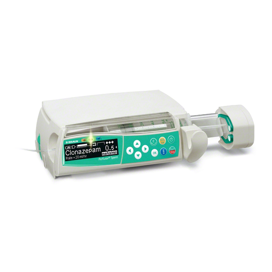
- Page 13 System Overview Description The Perfusor® Space (PSP) is according to IEC/EN 60601 resp. IEC/ EN 60601-2-24 a transportable infusion syringe pump for administrating fluids in the nutritional therapy and infusion technique as well as for home care applications. The medical specialist must decide on suitability for application on the basis of the warranted properties and the technical data.
- Page 14 System Overview Physical Construction Fig.: 1 - 2 Perfusor® Space Legend of fig. 1 - 2: ItemDesignation Perfusor® Space Connector “P2“ for SpaceStation module, external 12 V DC and accessories Drive head Connector “P3“, connection to SpaceControl module Syringe holder with piston brake Battery compartment cover Operating Unit Syringe area...
- Page 15 System Overview The Perfusor® Space housing mainly consists of the bottom part and the upper part. The battery module is inserted in the rear of the housing upper part. The opening is covered by the battery compartment cover. The operating unit is attached to the front of the bottom part with two hinges.
- Page 16 System Overview The pressure in the infusion system is measured through a strain gauge measuring in the drive head and monitored in the device electronics. The data from the strain gauge is continuously compared with the limit values which are calculated dependent on the selected syringe type and the pressure settings.
- Page 17 System Overview Fig.: 1 - 3 Block diagram Perfusor® Space Perfusor® Space, 1.0 gb 1 - 5...
- Page 18 System Overview Unit Software Approved Software Versions 688A030032 Basic software Position 1 2 3 4 5 6 7 8 9 10 688A030035 Digit 6 8 8 C 0 3 0 0 0 1 Improved functions 688A030040 Revision level Improved functions Hardware Languages French and Swedish added Software group...
- Page 19 PC is switched off, a component of the software may be seriously damaged so that repairs are no longer possible. In such a case the software cannot be updated via the PC and the device must be returned to B. Braun. Service Program Approved Version...
- Page 20 System Overview 1. Start the “HiBaSeD.exe” program (History, Barcode, Service, Drug list) on the PC. The Service Program is loaded and started and the initial window of the Service Program is displayed. 2. Read the notes carefully. 3. Mark the field “I accept all conditions” and then the field “Yes”...
- Page 21 System Overview The work window of the Service Program appears on the screen. All devices recognized are listed in the left column. Fig.: 1 - 8 5. Activate the desired device from the list on the left in the work window with a double-click. The device data is then displayed below the device name.
- Page 22 System Overview If the unit software version is not compatible with the Service Program version, a window opens prompting the operator to change the Service Program version. This window displays a compatibility list of the Service Program- and unit software versions.
- Page 23 System Overview Service Program Version Help Info ... 1. Open the “HiBaSeD“ window via . The current version of the Service Program is shown in this window. 2. Close the window by clicking “OK”. Fig.: 1 - 11 Compatibility List Help 1.
- Page 24 System Overview Technical Data All technical data is indicated in the instructions for use. Options The functions of the individual options are detailed in the instructions for use. Perfusor® Space Designation Part No.: Power supply Euro ......0871 3110A Power supply UK.
- Page 25 Unit Diagnosis / Calibration General WARNING WHILE TESTING THE UNIT AND TROUBLE SHOOTING THE OPERATOR/SERVICE TECHNICIAN MUST WORK WITH VOLTAGES UP TO 115 / 230 V AC. THESE VOLTAGES MAY CAUSE INJURIES WHICH ARE DANGEROUS TO LIFE AND LIMB. THE NATIONAL AND INTERNATIONAL SAFETY REGULATIONS ARE TO BE ADHERED TO.
- Page 26 Unit Diagnosis / Calibration The unit check, calibration and trouble shooting are subdivided into numbered working steps (Unit Test Step UTS, Calibration Step CS, Trouble Shooting TS) and are based on each other. Beginning with UTS 1 the operation described here has to be executed.
- Page 27 Unit Diagnosis / Calibration Alarms and Error Codes The alarms of the Perfusor® Space are classified in 5 categories. These categories are listed hereafter according to their importance. Alarm advice In case of unacceptable inputs corresponding messages are displayed (e.g. “Caution! Rate out of range“, “The parameter cannot be changed“) and a beep sounds.
- Page 28 Unit Diagnosis / Calibration Alarms Alarm Possible Cause Fault Clearance Battery nearly discharged (type: pre- The device was not connected to the Operate the device with battery until the alarm) mains long enough message “Battery discharged“ is displayed and the unit is switched off. Then connect the unit to the mains for at least 6 hours.
- Page 29 Unit Diagnosis / Calibration Device Alarms of the Function Processor Error Code Definition Possible Cause Fault Clearance 1001 ... 1013 Internal Error 1014 Loudspeaker not off Loudspeaker connector Check the loudspeaker connector Loudspeaker Check the loudspeaker 1015 Loudspeaker lost Loudspeaker connector Check the loudspeaker connector Loudspeaker Check the loudspeaker...
- Page 30 Unit Diagnosis / Calibration Device Alarms of the Control Microprocessor Error Code Definition Possible Cause Fault Clearance 1100 Timebase too fast Quartz of the processor PCB Exchange processor PCB 1101 Timebase too slow Quartz of the processor PCB Exchange processor PCB 1102 Timebase fail Quartz of the processor PCB...
- Page 31 Unit Diagnosis / Calibration Error Code Definition Possible Cause Fault Clearance 1201 different version FuP to KuP Software Update unit software Software 1202 E_ERROR_STEPMOTOR_1 Phase Drive motor, lead screw Exchange processor PCB not ok 1203 E_ERROR_STEPMOTOR_2 Current Motor drive Carry out calibration value not 0x55 Recognition of direction of rotation...
- Page 32 Unit Diagnosis / Calibration The Most Important Error Modes The following list specifies the most important error modes and their clearance. Note The device must be checked after every repair or service (see “Device Check“ pg. 2 - Error Possible Cause Fault Clearance The battery module discharges too fast The device was not used for a longer time.
- Page 33 Unit Diagnosis / Calibration Device Check Activity Function If yes If no The device is inserted in a SpaceStation or UTS 2 UTS 3 connected to a SpaceControl. Remove the device. UTS 4 Loosen all connections from the device. UTS 4 Remove syringe and close syringe holder.
- Page 34 Unit Diagnosis / Calibration Activity Function If yes If no Insert 2 ml / 3 ml syringe. On the LC display “Brake: stopped by holder” UTS 22 TS 21 appears in the line. Open syringe holder and remove syringe. On the LC display “Brake: stopped by light barrier” UTS 23 TS 21 appears in the line.
- Page 35 Unit Diagnosis / Calibration Activity Function If yes If no Insert syringe gauge for the strain gauge UTS 41 measurement, close syringe holder and select syringe type „#Lehre OPS50“. The syringe gauge must not be tipped. Therefore fix the syringe gauge so far into the syringe recess by hand that the piston brake moves back and the claws surrounds the pressure element.
- Page 36 Unit Diagnosis / Calibration Activity Function If yes If no Confirm syringe change, release syringe gauge and UTS 48 remove gauge. WARNING WHILE CHECKING THE MOTOR POWER LIMITATION WITH THE SYRINGE GAUGE THE SYRINGE HOLDER MUST NOT BE OPENED. THE SYRINGE GAUGE IS UNDER VERY HIGH PRESSURE AND MAY CAUSE INJURIES IF THE PRESSURE IS RELIEVED SUDDENLY.
- Page 37 Unit Diagnosis / Calibration Activity Function If yes If no Select pressure stage 6 and start infusion. When the maximum pressure of this pressure stage UTS 56 CS 1 is reached, the delivery is stopped, the red LED on the operating unit flashes and the message “Alarm / Drive blocked”...
- Page 38 Unit Diagnosis / Calibration Calibration Activity Function If yes If no Connect unit to PC with interface cable. CS 2 Start Service Program on the PC (see “Starting the The desired device is found by the Service Program CS 3 Service Program“...
- Page 39 Unit Diagnosis / Calibration 1. Start the Service Program (see “Starting the Service Program“ pg. 1 - 2. Select the unit to be calibrated in the left column of the window with a double mouse-click. The blue and the yellow LED blinks in opposite with the red LED.
- Page 40 Unit Diagnosis / Calibration 5. Input your user number in the window “Worker ID” as well as the six-digit serial number of the device, if necessary. 6. Confirm the input with “OK”. Fig.: 2 - 3 Note If HiBaSeD could not clearly read the device serial number, the number must be entered according to the rating plate.
- Page 41 Unit Diagnosis / Calibration Fig.: 2 - 6 Perfusor® Space, 1.2 gb 2 - 17...
- Page 42 Unit Diagnosis / Calibration 8. The frame “Data selection” is now activated. Fig.: 2 - 7 If the “Modify” button was pressed in the “Calibration procedure” frame, the desired data for editing and transmission can now be selected in the “Data selection” frame.
- Page 43 Unit Diagnosis / Calibration 9. Mark at least the “Calibration data“ field in this frame if you have not selected “New device” and confirm by clicking “OK”. The device switches on and the drive head moves to the extended end position. You are prompted to press the blue connection key on the device.
- Page 44 Unit Diagnosis / Calibration Fig.: 2 - 9 11. In the frame “Type of calibration” you can choose between a complete or a partial calibration. Select the desired calibration mode with the mouse pointer. Note The following description is applicable to a complete and a partial calibration.
- Page 45 Unit Diagnosis / Calibration 12. Press the “OK“ button after you have selected the calibration elements. The necessary device data is read out and stored in the PC. Fig.: 2 - 10 Fig.: 2 - 11 Fig.: 2 - 12 Fig.: 2 - 13 Perfusor®...
- Page 46 Unit Diagnosis / Calibration Fig.: 2 - 14 13. The frame “Element selection” is now activated. If you have selected a complete calibration in the “Type of calibration” frame, the individual calibration elements are already selected and cannot be changed. Actuate the “OK” button.
- Page 47 Unit Diagnosis / Calibration Claw Calibration 1. The frame “Claw calibration” is activated and calibration is started. 2. The claws in the drive head are closed and the query “Claw closed? Please confirm” is displayed in the frame “Claw calibration”. 3.
- Page 48 Unit Diagnosis / Calibration 4. Insert diameter gauge 23.4 mm and close the syringe holder. 5. Press the “OK” button. Fig.: 2 - 18 6. Insert diameter gauge 15.7 mm and close the syringe holder. 7. Press the “OK” button. Fig.: 2 - 19 2 - 24 Perfusor®...
- Page 49 Unit Diagnosis / Calibration 8. Insert diameter gauge 9.0 mm and close the syringe holder. 9. Press the “OK” button. Fig.: 2 - 20 10. Open the syringe holder and remove the diameter gauge. Press the “OK” button. Note The syringe holder must always be completely turned and the axial fastening completely opened.
- Page 50 Unit Diagnosis / Calibration 11. Close the syringe holder and actuate the “OK” button. If calibration was not terminated successfully, an error message is displayed on the PC screen. Fig.: 2 - 22 Pressure Calibration Note The term “Power gauge” in the windows of the Service Program corresponds to the syringe gauge.
- Page 51 Unit Diagnosis / Calibration 4. If “Insert power gauge and confirm with OK” is displayed in the frame “Pressure calibration/length/PWM”, open the syringe holder and remove the length gauge. WARNING DURING PRESSURE CALIBRATION WITH THE SYRINGE GAUGE THE SYRINGE HOLDER MUST NOT BE OPENED. THE SYRINGE GAUGE IS UNDER VERY HIGH PRESSURE AND MAY CAUSE INJURIES IF THE PRESSURE IS RELIEVED SUDDENLY.
- Page 52 Unit Diagnosis / Calibration This report can be printed out by pressing the “Print” button. Fig.: 2 - 27 2. Actuate the “OK” button to finish the calibration process and to store the data in the device. 2 - 28 Perfusor®...
- Page 53 Unit Diagnosis / Calibration Trouble Shooting Note The following trouble shooting cannot be carried out independently. It is based on the precise observance of the steps for the device check (see “Device Check“ pg. 2 - 9). From there reference is made to the corresponding trouble shooting steps. Activity Function If yes...
- Page 54 Unit Diagnosis / Calibration Activity Function If yes If no Switch on unit and insert syringe. The syringe piston is fastened with the syringe UTS 19 TS 23 holder blade and the default message is displayed on the LC display. Exchange processor PCB.
- Page 55 Disassembly / Assembly Perfusor® Space 3.1 General Remarks on Disassembly / Assembly Before disassembling the unit, the system must be checked (see “Device Check“ pg. 2 - 9) to isolate the part to be exchanged. The necessary steps to disassemble the complete unit, all its subsystems and spare parts are detailed in the following description.
- Page 56 Disassembly / Assembly Preparations for Exchanging the Processor PCB If the processor PCB is to be replaced a back-up of the pump settings is to be carried out, if this is still possible. 1. Start the Service Program (see “Starting the Service Program“ pg.
- Page 57 Disassembly / Assembly 4. Select the tab “IO”. 5. Press the “To file” button. In the window which opens now you are asked for the storage position of the file on the PC hard disk and the file name. Fig.: 3 - 2 6.
- Page 58 Disassembly / Assembly 7. Actuate the “Display” button to display the device data on screen. With “Close” the window is closed again. Fig.: 3 - 3 8. Select the storage position in the “Save as” window and input a unique file name. 9.
- Page 59 Disassembly / Assembly 10. Select the tab “Disposable articles”. Fig.: 3 - 5 11. Actuate the “From device” button. The data is read from the pump. The data of the disposable articles read out is displayed on screen. Perfusor® Space, 1.2 gb 3 - 5...
- Page 60 Disassembly / Assembly Fig.: 3 - 6 12. Press the “Save as” button. In the window which opens now you are asked for the storage position of the file on the PC hard disk and the file name. 3 - 6 Perfusor®...
- Page 61 Disassembly / Assembly 13. Select the storage position in the “Save as” window and input a unique file name. 14. Press the “Save” button. The data of the pump is saved on the PC hard disk. 15. Exit the Service Program (see “Quit the Service Program“...
- Page 62 Disassembly / Assembly Service Parts and Screw Kit All small parts, such as cover caps, are contained in a Perfusor® Space service part kit. Designation Ord. No. Service part kit Perfusor® Space ....3477 4270 with: housing cover cap (40 pieces) cover caps for operating unit (10 pieces)
- Page 63 Disassembly / Assembly 3.2 Battery Module Designation Ord. No. Battery compartment cover PSP , cpl....3452 0872 Battery pack SP (NIMH)......0871 3180 Disassembly Note Move the drive head to the extended end position before starting...
- Page 64 Disassembly / Assembly 2. Lift the lock (Fig.: 3 - 9 / Item 3) on the battery pack (Fig.: 3 - 9 / Item 1) and remove the battery pack out of the device. Fig.: 3 - 9 Legend of fig. 3 - 9: ItemDesignation Battery pack Battery compartment cover...
- Page 65 Disassembly / Assembly 3.3 Unit Foot Designation Ord. No. Unit foot (see “Service Parts and Screw Kit“ pg. 3 - 8) Disassembly 1. Pull the unit foot (Fig.: 3 - 10 / Item 1) out of the housing. Fig.: 3 - 10 Legend of fig.
- Page 66 Disassembly / Assembly 3.4 Operating Unit Designation Ord. No. Operating unit PSP, cpl......3452 0970 Hinge plate PSP, left ......3452 1011 Hinge plate PSP, right .
- Page 67 Disassembly / Assembly 4. Push the right and left connector locks (Fig.: 3 - 12 / Item carefully forward. 5. Disconnect the operating unit connection cable (Fig.: 3 - 12 / Item 1) from the connector. Fig.: 3 - 12 Legend of fig.
- Page 68 Disassembly / Assembly 6. Pull the operating unit from the left hinge plate (Fig.: 3 - 13 / Item 7. Pierce two cover caps (Fig.: 3 - 13 / Item 1) with a small screwdriver and remove cover caps. 8. Unscrew two screws and remove the left hinge plate. Fig.: 3 - 13 Legend of fig.
- Page 69 Disassembly / Assembly Disassembly 1. Pierce six cover caps (Fig.: 3 - 14 / Item 1) with a small screwdriver and remove cover caps. 2. Unscrew six screws and remove the rear panel (Fig.: 3 - 14 / Item Note The three screws of the keyboard must not be loosened.
- Page 70 Disassembly / Assembly 3. Push the right and left connector locks of the PCB keyboard carefully to the left. 4. Pull the LC display ribbon cable (Fig.: 3 - 16 / Item 1) out of the connector. Fig.: 3 - 15 Legend of fig.
- Page 71 Disassembly / Assembly 3.5 Upper Part of Housing Designation Ord. No. Upper part of housing PSP ..... . 3452 0910 Screws and cover caps (see “Service Parts and Screw Kit“...
- Page 72 Disassembly / Assembly 4. Unscrew two screws and remove the contact strip (Fig.: 3 - 18 / Item (Fig.: 3 - 18 / Item Note If necessary, the spring-mounted contact pins must be carefully inserted when the contact strip is dismounted. Fig.: 3 - 18 Legend of fig.
- Page 73 Disassembly / Assembly 3.6 Release Button Designation Ord. No. Release button PSP with leaf spring (see “Service Parts and Screw Kit“ pg. 3 - 8) Disassembly 1. Pull the release button (Fig.: 3 - 19 / Item 1) out of the housing bottom part.
- Page 74 Disassembly / Assembly 3.8 Drive Designation Ord. No. Drive PSP, cpl. Silver claws ....... 3452 1046 Green claws (as from unit software “F”) .
- Page 75 Disassembly / Assembly Fig.: 3 - 23 Legend of fig. 3 - 23: ItemDesignation Screw EJOT 22x8 WN 5451 TORX 6IP A2 Washer Fastening angle Carrier Screw EJOT 22x8 WN 5451 TORX 6IP A2 Drive head Perfusor® Space, 1.1 gb 3 - 21...
- Page 76 Disassembly / Assembly 6. Pull the drive motor connector (Fig.: 3 - 24 / Item 2) off the processor PCB. 7. Unscrew one screw (first temporary screw) and remove the processor PCB ground cable (Fig.: 3 - 24 / Item Fig.: 3 - 24 Legend of fig.
- Page 77 Disassembly / Assembly 8. Unscrew one screw (second temporary screw) and take the drive assembly (Fig.: 3 - 25 / Item 1) out of the housing. Note Please pay attention to the corresponding notes during assembly and installation (see “Assembly / Installation“ pg.
- Page 78 Disassembly / Assembly Disassembly of the Drive Head 1. Pierce two cover caps (Fig.: 3 - 27 / Item 4) with a small screwdriver and remove cover caps. 2. Unscrew two screws (Fig.: 3 - 27 / Item 3. Remove claws (Fig.: 3 - 27 / Item 2) carefully out of the drive head.
- Page 79 Disassembly / Assembly 7. Pull the claw mechanism (Fig.: 3 - 29 / Item 3) off the drive head cover (Fig.: 3 - 29 / Item 2) until the connection cable connector (Fig.: 3 - 30 / Item (Fig.: 3 - 29 / Item 1) can be easily accessed.
- Page 80 Disassembly / Assembly 10. Unscrew one screw (Fig.: 3 - 31 / Item 2) and remove the ground wire (Fig.: 3 - 31 / Item 1) of the drive PCB (Fig.: 3 - 31 / Item 3) from the driving tube. CAUTION Pay attention to the strain gauge (Fig.: 3 - 31 / Item...
- Page 81 Disassembly / Assembly 3.9 Syringe Holder with Piston Brake Designation Ord. No. Piston brake PSP ribbon cable....3452 0864 Syringe holder with piston brake PSP, cpl... 3452 0945 Syringe holder PSP spring .
- Page 82 Disassembly / Assembly 3. Unscrew one screw and remove the locking clip (Fig.: 3 - 33 / Item 2) from the piston brake PCB. Fig.: 3 - 33 Legend of fig. 3 - 33: ItemDesignation Screw EJOT 20x14 WN 5452 TORX 6IP Locking clip 3 - 28 Perfusor®...
- Page 83 Disassembly / Assembly 4. Open the right and left connector lock (Fig.: 3 - 34 / Item on the piston brake PCB carefully. Fig.: 3 - 34 Legend of fig. 3 - 34: ItemDesignation Piston brake connector lock 5. Pull the ribbon cable (Fig.: 3 - 35 / Item 1) out of the connector and remove the cable from the housing.
- Page 84 Disassembly / Assembly 6. Remove the syringe holder spring (Fig.: 3 - 36 / Item 1) from the post in the bottom part of the housing. Note The syringe holder spring can only be removed together with the piston brake drive. Fig.: 3 - 36 Legend of fig.
- Page 85 Disassembly / Assembly 11. Drive the piston brake motor with maximum 3 V DC. The blade is moved out of the syringe holder housing. Note If the blade moves into the syringe holder housing, then the polarity on the piston brake motor must be changed. 12.
- Page 86 Disassembly / Assembly 14. Unscrew one screw and remove the bearing cover (Fig.: 3 - 40 / Item 15. Take the lock (Fig.: 3 - 40 / Item 3) out of the bearing housing. Fig.: 3 - 40 Legend of fig. 3 - 40: ItemDesignation Screw EJOT 20x12 WN 5452 TORX 6IP Bearing cover...
- Page 87 Disassembly / Assembly 18. Unscrew two screws and remove guide rail (Fig.: 3 - 42 / Item 2) out of the bottom part of the housing. 19. Take piston brake motor assembly (Fig.: 3 - 42 / Item 4) out of the housing bottom part.
- Page 88 Disassembly / Assembly 3.10 Processor PCB Designation Ord. No. Processor PCB PSP ......3452 0880 (incl.
- Page 89 Disassembly / Assembly 3.11 Assembly / Installation Assembly or installation of the modules and subsystems is done in reverse order of disassembly. Special steps to be observed are described hereafter in detail. Only new cover caps are to be used. Special Screws Special screws for plastic housings are used in this unit.
- Page 90 Disassembly / Assembly Processor PCB When the processor PCB is replaced all data of the pump except for the calibration data was probably saved on a PC (see “Preparations for Exchanging the Processor PCB“ pg. 3 - Carry out the following steps to transmit the data back to the device.
- Page 91 Disassembly / Assembly Fig.: 3 - 44 4. Select the desired file with the mouse pointer and press the “Open” button. Fig.: 3 - 45 Perfusor® Space, 1.2 gb 3 - 37...
- Page 92 Disassembly / Assembly 5. Change to the tab “IO” and actuate the “To device” button. Fig.: 3 - 46 6. Press the “OK” button when the window “Confirmation” is displayed. Fig.: 3 - 47 3 - 38 Perfusor® Space, 1.2 gb...
- Page 93 Disassembly / Assembly 7. Enter your worker id in the window “Worker ID”. Press the “OK” button to transmit the data to the device. Fig.: 3 - 48 A message is displayed that a change of the device data may affect the patients.
- Page 94 Disassembly / Assembly 8. Select the tab “Disposable articles”. Fig.: 3 - 50 9. Press the “Load from“ button. The window “Open” is displayed on screen. 3 - 40 Perfusor® Space, 1.2 gb...
- Page 95 Disassembly / Assembly 10. Select the desired file with the mouse pointer and press the “Open” button. The data loaded is displayed on screen. 11. Actuate the “To device” button. Fig.: 3 - 51 Fig.: 3 - 52 Perfusor® Space, 1.2 gb 3 - 41...
- Page 96 Disassembly / Assembly 12. Press the “OK” button when the window “Confirmation” is displayed. Fig.: 3 - 53 13. Enter your worker id in the window “Worker ID”. Press the “OK” button to transmit the data to the device. Fig.: 3 - 54 A message is displayed that a change of the device data may affect the patients.
- Page 97 Disassembly / Assembly Loudspeaker 1. Route the loudspeaker connection cable between the drive motor and its connection wires, see Fig.: 3 - Fig.: 3 - 56 Piston Brake WARNING PAY ATTENTION TO THE PISTON BRAKE BLADE WHEN WORKING ON THE PISTON BRAKE. THE BLADE IS SHARP AND MAY CAUSE INJURIES.
- Page 98 Disassembly / Assembly Drive Head 1. Insert the drive head PCB with the strain gauge vertically in the drive head cover. Please note that the strain gauge must not get jammed in the guide. Note The three strain gauge tongues are level with the PCB upper side. 2.
- Page 99 Disassembly / Assembly Note Check the position of the emergency release tappet before mounting the drive head housing. Fig.: 3 - 60 5. Push the drive head housing on to the driving tube until the switch flag of the membrane tappet is positioned just before the claw mechanism.
- Page 100 Disassembly / Assembly Note Pay attention to the syringe wing sensor when inserting the side part of the housing and make sure that the sensor can be operated correctly. 1. Route the ribbon cable through the slide nut before pushing in the driving tube and then through the slide in front of the spindle nut when looking from the rear of the housing.
- Page 101 Disassembly / Assembly Operating Unit Note Before fitting the rear panel check the screw lengths. The screws may only be 4.5 mm long (without head). Longer screws must be exchanged. Note Before mounting the operating unit check the plastic foam gaskets in the housing opening for the connection cable to the operating unit.
- Page 102 Disassembly / Assembly Check List for Checks after Repair Visual Inspection Electrical Safety Functional Inspection according to IEC/EN 60601-1 or VDE 0750 and VDE 0751 Cleanliness The patient and housing leakage current of Locking with second unit Completeness the Perfusor® Space is caused exclusively by Operating unit magnets the operating voltage supply (Power Supply Battery compartment cover...
- Page 103 Disassembly / Assembly Visual Inspection Electrical Safety Functional Inspection according to IEC/EN 60601-1 or VDE 0750 and VDE 0751 Pressure cut off according to TSC Syringe type: "#Lehre OPS50“ Delivery rate: 200 ml/h WARNING REMOVE SYRINGE GAUGE ONLY WHEN RELEASED. DANGER OF INJURY! Strain gauge pressure measurement Pressure stage 1 _______ N...
- Page 104 Disassembly / Assembly For your notes: 3 - 50 Perfusor® Space, 1.0 gb...
- Page 105 For disinfection by wiping, you should use for example Meliseptol® from B. Braun. Allow the unit to dry for at least one minute. When you disinfect the device by spraying, make sure not to spray in the system openings (such as interface sockets and connectors, loudspeaker opening).
- Page 106 Servicing the Unit For your notes: 4 - 2 Perfusor® Space, 1.0 gb...
- Page 107 Checklist for Technical Safety Check – Every 24 Months Unit: Perfusor® Space User Manufacturer: B. Braun Melsungen AG Observe the Service Manual and the instructions for use. All measured values are to be documented. Accessories used should be included in testing. Make exclusive use of calibrated measuring equipment.
- Page 108 Technical Safety Check (TSC) Index d (Master - to be added to the documentation) Visual Inspection Electrical Safety Functional Inspection according to IEC/EN 60601-1 or VDE 0750 and VDE 0751 Pressure cut-off Syringe type: "#Lehre OPS50“ Delivery rate: 200 ml/h - Strain gauge pressure measurement Pressure stage 1 (9 ...
- Page 109 Checklist for Technical Safety Check – Every 24 Months Unit: Power Supply SP User Manufacturer: B. Braun Melsungen AG Observe the Service Manual and the instructions for use of the respective device. All measured values are to be documented. Make exclusive use of calibrated measuring equipment.
- Page 110 Technical Safety Check (TSC) Index d (Master - to be added to the documentation) For your notes: M001 32 10 05 F04 / 3891 6142 (GB) 6 - 2 Perfusor® Space, 1.0 gb Sheet 2 of 2...
- Page 111 Procedural Instructions on the TSC Visual Inspection Perfusor® Space 1. Check the Perfusor® Space and accessories for cleanliness. 2. Check the Perfusor® Space and accessories for completeness and check configuration. 3. Check the Perfusor® Space and its accessories for damage and the labels for readability.
- Page 112 Procedural Instructions on the TSC Electrical Safety Perfusor® Space according to IEC/EN 60601-1 The patient and housing leakage current of the Perfusor® Space is caused exclusively by the operating voltage supply (Power Supply or VDE 0750 and VDE 0751 SP or SpaceStation). The Technical Safety Checks of the power supply SP (drawing No.
- Page 113 Procedural Instructions on the TSC Functional Inspection Perfusor® Space Mechanical Inspection 1. Fit the unit to be tested on top of another Space device and check the proper functioning of the lock. 2. Fit the unit to be tested under another Space device and check the proper functioning of the lock.
- Page 114 Procedural Instructions on the TSC 3. Check syringe recognition. a) Insert approved 2 ml / 3 ml syringe. The syringe size is recognized. b) Insert approved 50 ml / 3 ml syringe. The syringe size is recognized. 4. Carry out infusion and bolus with any syringe and press all buttons at least once.
- Page 115 Procedural Instructions on the TSC Pressure Cut-Off (Strain Gauge Pressure Measurement) WARNING DURING THE STRAIN GAUGE MEASUREMENT WITH SYRINGE GAUGE THE SYRINGE HOLDER MUST NOT BE OPENED. THE SYRINGE GAUGE IS UNDER VERY HIGH PRESSURE AND MAY CAUSE INJURIES IF THE PRESSURE IS RELIEVED SUDDENLY. 1.
- Page 116 Procedural Instructions on the TSC 3. Disassemble push-button plate for Perfusor® Space from syringe gauge, insert syringe gauge and select syringe type “#Lehre OPS50”. Note The threaded end of the syringe gauge must be introduced in the opening of the motor power test adapter. Hold on to syringe gauge –...
- Page 117 Test Equipment and Special Tools Test equipment Designation Ord. No. For Device Check Syringe 2 ml / 3 ml Syringe 10 ml Syringe 30 ml Service connector SP ......3452 1062 HiBaSeD Service-CD .
- Page 118 Test Equipment and Special Tools Syringe gauge PSP ......0770 5204 “#Lehre OPS 50” with push-button plate and motor power test adapter for Perfusor®...
- Page 119 Test Equipment and Special Tools Special Tools Designation Ord. No. For Repairs TORX screwdriver kit 5 - 10, 25 TORX plus screwdriver kit 5 - 10, 25 Screwdriver 6IPx60 TORX plus ....4002 4806 Screwdriver 8IPx60 TORX plus .
- Page 120 Test Equipment and Special Tools For your notes: 8 - 4 Perfusor® Space, 1.0 gb...
- Page 121 Spare Parts List Item Designation Ord. No. Perfusor® Space Service part kit Perfusor® Space ... . . 3477 4270 with: housing cover cap (40 pieces) cover caps for operating unit (10 pieces) cover cap for syringe holder (10 pieces) cover cap for drive head and claw (20 pieces) housing foot (20 pieces)
- Page 122 Spare Parts List Fig.: 9 - 1 Exploded drawing Perfusor® Space 9 - 2 Perfusor® Space, 1.3 gb...
- Page 123 Spare Parts List Battery compartment cover PSP , cpl..3452 0872 Battery pack SP (NIMH) ....0871 3180 Operating unit PSP, cpl.
- Page 124 Spare Parts List 9 - 4 Perfusor® Space, 1.0 gb...
- Page 125 Revision Documentation 10 - Description of Version Version 1.0 (Base Version) First edition of this Service Manual Release date: 07.01.05. Version 1.1 Description for disassembly of the drive head added. Claw mechanism and drive head PCB added as new spare parts.
- Page 126 Revision Documentation 10 - 2 Perfusor® Space, 1.0 gb...
- Page 127 Revision Documentation Title page and pages preceding main body Page 2 - 9 ........Version 1.1 Page 0 - 1 .
- Page 128 Revision Documentation Page 3 - 13 ........Version 1.0 Page 3 - 49 .
- Page 129 Revision Documentation Page 10 - 3 ........Version 1.0 Page 10 - 4 .
- Page 130 Revision Documentation 10 - 6 Perfusor® Space, 1.0 gb...
- Page 131 Index 11 - Accessories ........1 - 12 Housing Alarms .
Need help?
Do you have a question about the Perfusor Space and is the answer not in the manual?
Questions and answers