Table of Contents
Advertisement
Introduction
Thank you very much for purchasing this excellent Alinco transceiver.
Our products are ranked among the finest in the world. This radio has
been manufactured with state of the art technology and it has been tested
carefully at our factory. It is designed to operate to your satisfaction for
many years under normal use.
Please read this manual completely from the first page to the
last, to learn all the functions the product offers. It is important to
note that some of the operations may be explained in relation to
information in previous chapters. By reading just one part of the
manual, you may risk not understanding the complete explanation
of the function.
Before transmitting
There are many radio stations operating in proximity to the frequency
ranges this product covers. Be careful not to cause interference when
transmitting around such radio stations.
Electromagnetic Interference/Compatibility
■
During transmissions, your radio generates RF energy that can
possibly cause interference with other devices or systems. To avoid
such interference, turn off the radio in areas where signs are posted to
do so. DO NOT operate the transmitter in areas that are sensitive to
electromagnetic radiation such as hospitals, aircraft, and blasting sites.
Features
■ Ultra compact, Output power selectable 60W/25W/10W
■ PC-programmable 200ch
■ Alphanumeric name tags
■ Wide variety of selective calling features built-in; The
2-Tone, 5-Tone, 51 CTCSS, 1024 DCS, 4 Tone-burst tones
and DTMF/ANI decode
■ Radio stun/kill/revive functions to protect your
communication security
■ Bright LCD and easy-to-operate backlit
■ Multi-function, backlit microphone enables direct
frequency entry & more from keypads
■ Various scan modes, Key lock, Wide/Narrow operations
Advertisement
Table of Contents

Related Manuals for Alinco DR-CS10


Summary of Contents for Alinco DR-CS10
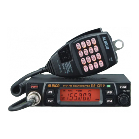
- Page 1 Features Introduction ■ Ultra compact, Output power selectable 60W/25W/10W Thank you very much for purchasing this excellent Alinco transceiver. Our products are ranked among the finest in the world. This radio has ■ PC-programmable 200ch been manufactured with state of the art technology and it has been tested carefully at our factory.
- Page 2 WARNING To prevent any hazard during operation of Alinco’s radio product, in this manual and on the product you may find symbols shown below. Please ALERT read and understand the meanings of these symbols before starting to use the product.
- Page 3 WARNING Handling this product Do not modify or remove fuse-assembly from the DC-cable. It may result in fire,electric shock and/or damage to the product. Be sure to reduce the audio output level before operating. Excessive audio may damage hearing. Do not open the unit without permission or instruction from the manufacturer. In case of emergency Unauthorized modification or repair may result in electric shock, fire and/or In case of the following situation(s), please turn off the product, switch...
- Page 4 WARNING About power-supply CAUTION Use only reliable power supply of specific DC output range and be mindful of Environment and condition of use the polarity of the cables and DC jack. Always turn off the power supply when connecting or disconnecting the Do not use the product in proximity to a audio products such as TV, radio cables.
- Page 5 Any vehicle does not present a safe environment during lightning. This environment becomes much more dangerous if an outdoor antenna is installed on the car. Move the antenna and its cable into the car at the first sight of forthcoming thunderstorm and lightning. At any case Alinco declines any responsibility against any damages caused by lightning and other desasters.
-
Page 6: Table Of Contents
CONTENTS KEY OPERATIONS ..............12 Supplied Accessories/Optional Accessories .....1 Supplied Accessories ............... 1 Squelch Off/Squelch Off Momentarry ..........12 Initial Installation ..............2 Frequency Scan ................12 Memory Scan ................... 12 Mobile installation ................2 CTCSS/DCS Encode and Decode setup ......... 12 DC Power Cable Connection ............ - Page 7 CONTENTS Busy Channel Lockout ..............24 Reverse TX/RX ................18 Reverse TX/RX ................24 Talk Around ..................19 TOT (Time-out timer) ............... 24 Radio's DTMF Self ID Enquiry ............19 CTCSS/DCS Encode and Decode ........... 24 Radio's 5TONE Self ID Enquiry ............19 Talk Around ..................
-
Page 8: Supplied Accessories/Optional Accessories
The standard accessories may vary slightly depending on the version you have purchased. Please contact your local authorized Alinco dealer should you have any questions. Alinco and authorized dealers are not responsible for any typographical errors there may be in this manual. Standard accessories may change without notice. -
Page 9: Initial Installation
Initial Installation Mobile installation Determine the appropriate angle of the transceiver, using the screw hole position on the side of the mounting bracket. The transceiver may be installed in any position in your car, where the controls and microphone are easily accessible and it does not interfere with the safe operation of the vehicle. -
Page 10: Dc Power Cable Connection
Initial Installation Connect the DC power cable to the transceiver's power supply DC Power Cable Connection connector. Press the connectors firmly together until the locking tab clicks. Mobile Operation The vehicle battery must have a nominal rating of 12V. Never connect the transceiver to a 24V battery. - Page 11 Initial Installation Connect the transceiver's DC power connector to the connector on Fixed Station Operation the DC power cable. In order to use this transceiver for fixed station operation, you will need Press the connectors firmly together until the locking tab clicks. a separate 13.8V DC power supply (not included) , Please contact local dealer to require.
-
Page 12: Power Supply Voltage Display
Initial Installation Accessories Connections Power supply voltage Display After being connected to an appropreate power source, press External Speaker to turn on. Press and hold key for 2 seconds to display the supplied If you plan to use an external speaker, choose a speaker with an voltage. - Page 13 Initial Installation Microphone For voice communications, connect a provided microphone into the socket on the front of the main unit. Turn the ring firmly on the plug until it locks. Attach the supplied microphone hanger in an appropriate location using the screws included in the screw set. Microphone connector Microphone [EMS-74]...
-
Page 14: Getting Acquainted
Getting Acquainted Front panel Functions that require pressing key until icon appears then FUNC press the following key. NO. KEY FUNCTION MW(Setting memory channel data) FUNC Deleting memory channel Keypad lockout High/Middle/Low power Functions that require holding for over 2 seconds the following key. NO. -
Page 15: Rear Panel
Getting Acquainted Rear panel NO. KEY Å FUNCTION (Not in use) Memory mode. Indicates the channel number in memory mode. Channel skip. Indicates the decimal point of frequency and the Decimal point scanning function. Indicates the frequency or memory name. Signal is being received or monitoring. -
Page 16: Microphone
Getting Acquainted microphone MIC Connector Diagram(in the front view of connector) NO. KEY FUNCTION Increase frequency, channel number or setting value. DOWN Decrease frequency, channel number or setting value. Push-To-Talk key to transmit. Numerical Keyd Input VFO frequencies and other various oprations. DTMF ON/OFF Switches between DTMF and function operations. -
Page 17: Basic Operations
Basic Operations Adjusting Frequency/Channel PWR KEY Switching The Power On/Off In frequency (VFO) mode, you can change the current frequency to Press the switch to power on. Press the the desired one through microphone [ ] key. Press key for 1 second to turn off. key to increase frequency and press key to decrease frequency. -
Page 18: Transmitting Tone Burst Tone
Basic Operations Speaking too loud distorts, too undertone won't modulate enough your MEMORY CHANNEL DELETING voice. Under Memory mode, input by MIC's numeric keys to select While transmitting, LED lights RED and TX-meter shows relative power level. channel to be deleted. For example, choosing CH1, press [0] [0] [1]. Release PTT to receive. -
Page 19: Key Operations
KEY OPERATIONS squelch off(Monitor function:) CTCSS/DCS Encode and Decode setup Many repeaters require CTCSS or DCS Squelch Off: Press key to disable squelch, press key again tone encoding to access the system. Tone to resume squelch. While monitoring, all signaling features are decoding features are often used to filter temporary released. -
Page 20: Ctcss Scan
KEY OPERATIONS The standard set of 50 different CTCSS tones are available. DCS Offset Direction and offset frequency setup encode/decode cannot be separated. The list of selectable tones and Repeater receives a signal(UP-LINK) on one frequency and re-transmits codes is shown on Appendix at the end of this manual. on another frequency(DOWN-LINK). -
Page 21: Keypad Lockout
KEY OPERATIONS Emergency Alarm KEYPAD LOCKOUT This transceiver has 4 optional Alarm modes that can only be set using Avoiding unintentional operation, this function will lock all keys except programming software. Press pre-programmed key to display "ALARM" FUNC to operate. Repeat above operation or turn off the transceiver to cancel the alarm. -
Page 22: Function Menu Setup
FUNCTION MENU SETUP Frequency Step Setup IMPORTANT: All or a part of operation in this chapter may not be available to dealer-programmed units. Only in VFO mode, this function is valid. Press and hold key for over 2 seconds to enter the FUNCTION Press and hold key for over 2 FUNC... -
Page 23: Sending 2-Tone Call
FUNCTION MENU SETUP "2TONE": The channel will be mute Sending 5-Tone Call by a 2-Tone signal. The speaker won’t Press and hold key for over 2 seconds to enter setting menu. FUNC sound until receiving a correspondent Press key to choose No.04 menu, 2-Tone signal. -
Page 24: Signaling Combination Setup
FUNCTION MENU SETUP Signaling Combination setup HIGH/MID/LOW Power Selection This function is to improve the level of protecting the radio against Press and hold key for over 2 FUNC receiving irrelative signal. seconds to enter setting menu. Press and hold key for over 2 seconds to enter setting menu. -
Page 25: Tx Off Setup
FUNCTION MENU SETUP TX OFF SETUP OFF: Busy channel lockout is disabled. It can transmit in any receiving status. This function is to prohibit the transmission and to use the radio as a receiver. Press key to confirm and exit. Press and hold key for over 2 seconds to enter setting menu. -
Page 26: Talk Around
FUNCTION MENU SETUP Talk Around beep sound By Talk Around function, you can directly communicate with other radios The beep provides confirmation of entry, error status or malfunctions of in your group in case the repeater is not activated or when you are out of the radio. -
Page 27: Apo (Auto Power Off)
FUNCTION MENU SETUP APO (Auto power off) Display iiiumination color setting Once APO is activated, the radio will be automatically switched off when This is to select the display illumination color. the pre-set time is elapsed. Press and hold key for over 2 seconds to enter setting menu. FUNC Press and hold key for over 2... -
Page 28: Tone-Burst Tones
FUNCTION MENU SETUP Press key to confirm the selection and exit. PIN Setup( Useless if PIN is not assigned Enable this function, you have to insert a matching PIN to enter into tone-burst tones normal status when radio is turned on.(The PIN can be assigend by Press and hold key for over 2 seconds to enter setting menu. -
Page 29: Reset ( May Be Blocked For Dealer-Programmed Units )
FUNCTION MENU SETUP After finishing edition, press to confirm and enter into edition of current group's ID corresponding name.Press select desired letter, press to move cursor to next edition, press to clear out all letters. 00-127, total 128 group ID and corresponding ID name. -
Page 30: Microphone Operation
Microphone Operation Switches between VFO and MEMORY mode DOWN UP In standby, press key to switch between memory mode and Frequency mode (VFO). Short Calling Press PTT switch and key to transmit the selected Numeric Keys DTMF/2TONE /5TONE in current channel. Transmitting DTMF Code:In standby, press , LCD displays Lock Switch... -
Page 31: Scan Skip
Microphone Operation OFF: Busy channel lockout is disabled. This function can be temporarily used in memory mode. Once the Press number keys to confirm and exit. radio is turned off or switched to another channel, the temporary setting will be erased and back to initial settings. Reverse TX/RX Scan Skip To exclude selected channels from memory scanning... -
Page 32: Talk Around
Microphone Operation Press number key to confirm and exit. LCD displays icon, it indicates CTCSS encode set in current channel. HIGH/MID/LOW Power Selection LCD displays icon, it indicates CTCSS encode and decode set in current channel. In standby, press , then press , LCD displays "POW-XX". -
Page 33: Cable Clone
Cable Clone This feature clones the programmed data and parameters in the master unit to slave units. Pre-programming is required using a dealerware. Use optional EDS-29 cloning cable as shown below. Make a master unit by setting and programming it as desired. Turn off both units. Connect the cable between the DATA jacks on both units. -
Page 34: Maintenance
Maintenance Key Function Trouble Shooting The function of key combinations can be changed by PC software. Problem Possible Causes and Potential Solutions Below is the default setting. + and - polarities of power connection are (a) Power is on, nothing reversed. -
Page 35: Specifications
Specifications General Receiver Wide band Narrow band Frequency Range VHF: 136-174MHz Sensitivity ≤0.25μV ≤0.35μV (12dB Sinad) Number of Channels 200 channels Adjacent Channel ≥70dB ≥60dB Selectivity 25KHz (Wide Band) Channel Spacing 20KHz (Middle Band) Intermodulation ≥65dB ≥60dB 12.5KHz (Narrow band) Spurious Rejection ≥70dB ≥70dB... -
Page 36: Appendix
Appendix 51 groups CTCSS Tone Frequency(Hz) 1024 groups DCS Code. 62.5 67.0 79.7 94.8 110.9 131.8 156.7 171.3 186.2 203.5 229.1 69.3 82.5 97.4 114.8 136.5 159.8 173.8 189.9 206.5 233.6 71.9 85.4 100.0 118.8 141.3 162.2 177.3 192.8 210.7 241.8 74.4 88.5 103.5 123.0 146.2 165.5 179.9 196.6 218.1 250.3 77.0 91.5 107.2 127.3 151.4 167.9 183.5 199.5 225.7 254.1... - Page 37 Appendix N is positive code, I is negative code, total: 1024groups.
Need help?
Do you have a question about the DR-CS10 and is the answer not in the manual?
Questions and answers