
Related Manuals for Mitsubishi Electric LU2-4710-B1T


Summary of Contents for Mitsubishi Electric LU2-4710-B1T
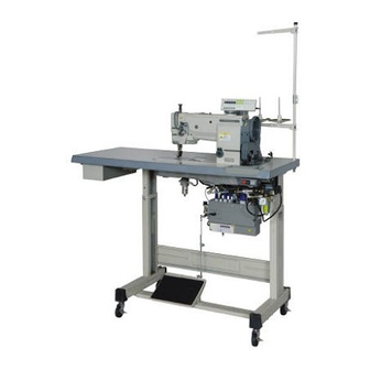
- Page 1 LOCKSTITCH COMPOUND-FEED AUTOMATIC UNDERTRIMMER INDUSTRIAL SEWING MACHINES MODEL LU2-4710-B1T (Single-Needle) LU2-4730-B1T (Double-Needle) INSTRUCTION MANUAL A180E363P05...
- Page 2 INTRODUCTION Thank you very much for purchasing Mitsubishi industrial sewing machine. Please read this instruction manual before operating the sewing machine. Please read also “Safety Manual” , “Instruction manual for Mitsubishi Limiservo X” and operate the sewing machine correctly and safely. PRECAUTION BEFORE STARTING OPERATION Safety Precautions 1 . When turning the power on, keep your hands and fingers away from the area around/ under the needle and the area around the pulley. 2 . The power must be turned off when the machine is not used, or when the operator leaves his/her seat. 3 . The power must be turned off before tilting the machine head, installing or removing the “V” belt, adjusting the machine, or replacing parts. 4 . Avoid placing fingers, hairs, obstacles, etc. near the pulley, “V” belt, bobbin winder wheel, or motor when the machine is in operation. Injury could result. 5 . Don’t put fingers into the thread take-up lever cover, around/under the needle, or pulley when the machine is in operation. 6 . If the belt cover, the finger guard, and/or the eye guard are installed, don’t operate the machine without these safety devices.
-
Page 3: Table Of Contents
CONTENTS PREPARATION FOR OPERATION ……………………………………………… 1 1 Connecting the electric cables to the control box ……………………………… 1 2 Setting up the activating speed of the air cylinder … …………………………… 2 3 Adjustment of the needle stopping position … …………………………………… 2 USAGE PRECAUTION ……………………………………………… 3 1 Lubrication (1) ………………………………………………………………………… 3 2 Lubrication (2) ………………………………………………………………………… 3 3 Lubrication condition … ……………………………………………………………… 4 4 Adjustment of lubrication to the rotating hook ………………………………… 4 5 Precaution for the built-in type detector ………………………………………… 4 6 Installation of the belt cover ………………………………………………………... -
Page 4: Connecting The Electric Cables To The Control Box
PREPARATION FOR OPERATION 1 Connecting the electric cables to the control box Connect wires and pipes as follows. ( 1 ) Connect the cables ① extended from the sewing machine head to the control box, and then connect 3-pin connector ② to the solenoid valve ③ used for activating the air cylinder to alternating movement instantly. Note: Set the standard air pressure of the regulator (option) to 5 kgf/cm (2) In case of using the knee switch ④ as the alternating switch, connect 2-pin connector ⑤ of OPTION B to the knee switch ④. (3) Connect the urethane tube ⑥ extended from the sewing machine head to A port ⑦ of the solenoid valve ③. Note: For your safety, always turn off the power switch whenever connect or disconnect connectors. Air cylinder used for alternating movement is built in the sewing machine head ⑥ Regulator ① (Option) ④ A port to the flow control ⑦ P port to Knee switch the air supply source LF-FM-CFT ⑤ (Option) R port ... -
Page 5: Setting Up The Activating Speed Of The Air Cylinder
PREPARATION FOR OPERATION 2 Setting up the activating speed of the air cylinder ( 1 ) When control the pulling speed of the air cylinder, adjust the air flow of A port on the solenoid valve. ( 2 ) When control the pushing speed of the air cylinder, adjust the exhaust valve of R port on the solenoid valve. 3 Adjustment of the needle stopping position 1 . Adjustment of “UP” position When the pedal is kicked down by heel, the machine stops at “UP” position. If marks deviate larger than 3 mm, adjust as follows. ( 1 ) Disconnect the plug (12 pins) of cable from the machine head. -
Page 6: Usage Precaution
USAGE PRECAUTION 1 Lubrication (1) 2 Lubrication (2) Fill the oil reservoir with oil up to “H” mark. When a new sewing machine is used for the Oil level should be periodically checked. If oil level first time, or sewing machine left out of use for is found below “L” level replenish oil to “H” level. considerably long time is used again, replenish a For oil, use “MC70M” specified by Mitsubishi. suitable amount of oil to the portions indicated by ※ Refer arrows in the below figure. MC70M : Specific gravity (15℃ ) = 0.86 (g/cm :Viscosity (40℃ ) = 10.9 (mm Oil level mark — 3 —... -
Page 7: Lubrication Condition
USAGE PRECAUTION 3 Lubrication condition 4 Adjustment of lubrication to the rotating hook See dripping of oil through the oil sight window to check oiling condition during operation. Adjusting Decrease Increase screw Oil sight window 5 Precaution for the built-in type detector 1 . Since the optical type detecting element is used in the detector, prevent dust or oil from sticking to the detecting plate when the sewing machine pulley is removed for adjustment. If they have stuck, wipe them off with soft cloth carefully so that the surface is not scratched, do not let oil permeate the clearance on the detecting plate. 2 . In case of disconnection of the position detector connector, running off the belt or complete constraint and over load, the motor is automatically turned off after predetermined time to prevent burning of the motor. (However, in case of half-constraint and over load, the power may not be turned off.) After the failure is eliminated, the normal operation is resumed by turning off the power once then turning on again. The same operation occurs for the detector malfunction or the line breakage. -
Page 8: How To Use
HOW TO USE HOW TO USE 1 Installation of needles Note: Before installing the needles, be sure to turn off the power. Double-Needle Single-needle Insert the needle upto the bottom of needle Insufficient insertion Needle distorted clamp and tighten the screw keeping the long groove side of needle face to face Long grooves are opposite Long groove left side 2 Winding of the bobbin thread Note: When bobbin thread is wound, keep the presser foot lifted. Adjustment ●Tension of wound thread Slack winding is recommended for polyester thread and nylon thread. -
Page 9: Selection Of The Thread
HOW TO USE 3 Selection of the thread It is recommended to use “S” twist thread in the left needle (viewed S twist thread from front), and “Z” twist thread in the right needle. When discriminate use of needle threads is impossible, use “Z” twist thread in both the needles. Z twist thread For bobbin thread, “S” twist thread as well as “Z” twist thread can be used. 4 Threading of needle threads 1 . Pass each needle thread through thread guide (A). Note: When thin slippery thread (polyester thread or filament thread, etc.) is used, Pass the thread through thread guide (B) as well. 2 . With the thread take-up lever located at the upper most position, pass each needle thread in the order shown in the following figure. -
Page 10: Adjustment Of Feed (Stitch) Length And Backstitch
HOW TO USE HOW TO USE 5 Adjustment of feed (stitch) length and backstitch ● A djustment of feed (stitch) length…Adjust feed length by turning the feed length setting dial while pushing PUSH lever. Note: D epending upon the stitch length, the maximum sewing speeds are different. With referring to the specifications on page 24, please operate the sewing machine at the speed less than the matching sewing speed with the stitch length. ● B ackstitch…Direction of stitching can be reversed by depressing the reverse sewing lever or pushing the touch back switch. Feed length setting dial Reverse sewing lever Touch back switch 6 Setting of bobbins 7 Adjustment of the needle thread guide ( 1 ) Pull out 5cm thread tail from bobbins. -
Page 11: Threading Of Bobbin Threads
HOW TO USE 8 Threading of bobbin threads : Balance of threads tension ( 1 ) Put bobbin thread into the slit ①, pass under A ○ the lug ② and extend it above the bed. Balanced tension Thread ① B × Tight the needle thread tension or loose the bobbin thread tension C × Loose the needle thread tension or tight the bobbin thread tension Thread ② Opener A Adjustment of needle threads tension ( 2 ) While holding two needle threads with your Adjust needle threads tension by turning thread left hand, turn the pulley one rotation with tension nuts. -
Page 12: C Adjustment Of The Thread Take Up Spring
HOW TO USE HOW TO USE C Adjustment of the thread take up spring 1 . Adjusting movable range of the thread take up spring ( 1 ) To adjust the thread take up spring ① for ⑥ the left thread, loosen the stopper stop screw Decrease ⑤ ② and move the stopper ③. Increase Note: In case of LU2-4710, adjust only step (1). ② ③ ( 2 ) To adjust the thread take up spring ④ for the right thread, loosen the stopper stop screw ⑤ and move the stopper ⑥. - Page 13 HOW TO USE 2 . To change the balance of the alternating movements between the outside presser foot and inside presser foot ( 1 ) For example, to increase the rise of the inside presser foot, and decrease the rise of the Inside presser foot outside presser foot. ① R emove the rubber plug located on the top cover. 2.0 to 6.0 mm ② T urn the pulley until the outside presser foot is slightly raised from the throat plate. ③ L oosen the set screw Ⓐ located on the feed Outside presser foot lifting rock shaft crank (right).
-
Page 14: E Instant Alternating Switch
HOW TO USE E Instant alternating switch Alternating stroke adjusting dial During the sewing operation, if a sewing material Stopper screw has a step, hit the instant alternating switch, then the alternating up and down movement instantly becomes much bigger to get over the step. Hit once, ON The alternating up and down movement becomes highest (It is adjusted 6 mm is (Lighting LED lamp) Instant alternating switch the highest when the sewing machine is shipped from the factory). Hit twice, OFF The alternating up and down movement becomes the normal stroke controlled with the alternating stroke adjusting dial. Note 1: T he knee switch also can be used as the instant alternating switch. 2: I t also can be set the alternating up and down movement to the highest only while pressing the instant alternating switch. -
Page 15: G Installing The Feed Regulator Bracket
HOW TO USE G Installing the feed regulator bracket If it is necessary to dismount and reassemble the feed regulator bracket and its related parts, install Ⓒ Feed regulator shaft it as follows. Note: I f the feed regulator bracket is poorly positioned, the resultant alternating 42.6 mm movements may be too short or long causing defective machine operation. Ⓑ ( 1 ) Set the gap between special screw Ⓐ located on the regulator shaft and the side wall of Feed regulator bracket Ⓐ 2.3 mm the machine arm to 42.6 mm as illustrated to the left. (Use a 42.6 mm spacer between these parts. This facilitates the operation.) ( 2 ) With the feed regulator stud held as explained Feed lifting rock shaft crank (right) in step ( 1 ) above, adjust the feed regulator bracket. This adjustment should insure a gap of 2.3 mm between the periphery of pin Ⓑ... -
Page 16: I Timing Between The Rotating Hook Motion And The Needle Motion
HOW TO USE HOW TO USE I Timing between the rotating Screw Ⓑ hook motion and the needle motion In case of double-needle, adjust right and left timing in the same way at the same time. Link Note: If you remove the presser foot, the throat plate, and the feed dog, it makes easier to adjust. Set Screw Ⓓ ( 1 ) Set feed length to 6 mm. Screw Ⓒ Screw Ⓐ ( 2 ) Loosen two screws Ⓐ, and remove the link. ( 3 ) Loosen all screws Ⓑ, Ⓒ, Ⓓ. (a) Position of the needle bar: (b) Position of the needle bar: ... -
Page 17: J Adjustment Of The Feed Dog Height
HOW TO USE J Adjustment of the feed dog height The feed dog height and the presser foot pressure must be adjusted according to the fabric. ◆ The fabric will be damaged if the feed dog extends too high, or if the presser foot Feed dog pressure is too large. 1.0 mm ◆ An even stitch length cannot be assured if Throat plate the feed dog is too low, or if the presser foot pressure is too small. ◆ The feed dog height is the position where the needle is at the top position. Adjustment of the feed dog height ( 1 ) Lean the machine head backward. ( 2 ) Turn the pulley by hand and stop it at the position where the feed dog rises to the maximum height. -
Page 18: K Relationship Between The Rotating Hook Motion And The Thread Take-Up Lever Motion
HOW TO USE HOW TO USE K Relationship between the rotating hook motion and the thread take-up Black line on boss of lower shaft bearing lever motion Timing belt When the timing belt is removed for replacement, etc., the relation between the rotating hook motion and the thread take-up lever motion should be adjusted as follows: ( 1 ) Turn the pulley and stop when the thread take-up lever is lifted to the highest position. ( 2 ) Lean the machine head backward and check that the arrow (timing mark) put on the timing belt is aligned with the black line on the boss of lower shaft bearing. ( 3 ) If the timing mark is not in line with the black line, remove the timing belt and install Timing belt pulley it again to adjust. -
Page 19: M Relationship Between The Needle Motion And The Feed Dog Motion
HOW TO USE M Relationship between the needle motion and the feed Feed rock shaft crank (middle) dog motion Feed rock shaft crank (right) ( 1 ) Set the stitch length to “0” on the feed length setting dial. Ⓐ Screw ( 2 ) Set the needle at the lowest position. Ⓑ Screw ( 3 ) Lean the machine head backward. Link ( 4 ) Loosen the feed rock shaft crank set screws Ⓐ, Ⓑ. -
Page 20: N Safety Clutch
HOW TO USE HOW TO USE N Safety clutch Timing belt pulley ● A safety clutch is installed to prevent the Safety clutch hook or timing belt damage if the thread is caught in the hook when the machine is loaded abnormally during operation. 1 ) Function of the safety clutch Bushing ( 1 ) When the safety clutch functions, the timing belt pulley will be freed, and the lower shaft rotation will stop. The upper shaft only will rotate. Stop the operation of the machine. ( 2 ) Completely remove the thread, etc. caught in the hook. ( 3 ) Turn the bushing by hand, and check Pulley whether the lower shaft rotates lightly and properly, then install the clutch device as... -
Page 21: O Adjustment Of Upper Feed Length (Needle Side)
HOW TO USE O Adjustment of upper feed Upper feed length (needle side) increases If uneven feeding occurs according to the fabric, Special bolt adjust the long hole of the feed rock shaft crank (right) to adjust the upper feed length. Link Reference (How to adjust) line ( 1 ) Loosen the special bolt. Upper feed ( 2 ) Move the special bolt upward to decrease the upper feed. decreases ( 3 ) Move the special bolt downward to increase the upper Feed rock shaft feed. (The upper feed and the lower feed theoretically crank(right) become equal when the center of the special bolt matches the reference line of the feed rock shaft crank) ( 4 ) After adjusting, tighten the special bolt. -
Page 22: Q Installation Of The Movable Knife
HOW TO USE HOW TO USE Q Installation of the movable knife 1 . Initial position of the movable knife ( 1 ) Turn the pulley and stop it at the position where the needle comes to the lowest. ( 2 ) Put the cam roller into the thread trimmer cam groove by pushing the cam follower crank. ( 3 ) In this condition, turn the pulley and stop it at the position where the black mark point on the arm meets the white mark point on the pulley. Set the cam follower crank at this position with a screwdriver temporarily preventing the cam roller coming out from the cam groove. ( 4 ) Loosen bolts Ⓐ and Ⓑ. ( 5 ) Adjust so that the tip slant portion of the movable knife protrudes 0 to 0.5 mm from the fixed knife, as shown in the figure and tighten bolts Ⓐ and Ⓑ. -
Page 23: R Installation Position Of The Thread Trimmer Cam
HOW TO USE R Installation position of the thread trimmer cam ( 1 ) Adjust so that the gap between the feed cam and the bushing is 17.3 mm and then tighten Reverse block the screw Ⓐ to the flat on the lower shaft. ( 2 ) Place the thread trimmer cam on the end face of the bushing and the thread tension releasing cam on the end face of the thread trimmer cam (making the gap between each Thread tension releasing cam part zero), then tighten each screw. Bushing Screw Ⓐ Feed connecting rod 17.3 mm Thread trimmer cam Feed cam S Adjustment of the thread trimmer cam ( 1 ) Turn the pulley and stop it at the position where the needle comes to the lowest. -
Page 24: T Adjustment Of The Thread Tension Releasing
HOW TO USE HOW TO USE T Adjustment of the thread tension releasing ( 1 ) Turn the pulley and stop it at the position where the needle comes to the lowest. ( 2 ) Put the cam roller into the thread trimmer cam groove by pushing the cam follower crank. ( 3 ) Turning the pulley, adjust the thread tension releasing cam so that the thread tension disc closes when the white mark point on the pulley comes in line with the black mark point on the arm. To adjust, loosen two thread tension releasing cam clamp screws Ⓐ. ( 4 ) The opening amount of the thread tension disc should be adjusted with the thread tension releasing roller Ⓑ mounted on the convex portion of the thread tension releasing cam, as shown in the figure. To adjust, loosen screws Ⓒ and pull the wire. ( 5 ) Make fine adjustments by loosening the nut Ⓓ. ( 6 ) Loosen the nut Ⓓ and make the outer casing approach to the right to increase the opening amount. White mark point Cam follower crank Thread tension ... -
Page 25: U Adjustment Of Meshing Pressure Between The Movable Knife And The Fixed Knife
HOW TO USE U Adjustment of meshing pressure between the movable knife and the fixed knife ( 1 ) Loosen the fixed knife bracket clamp bolt Ⓐ. ( 2 ) Adjust meshing pressure by turning the up and down adjusting screw Ⓑ, and tighten the bolt Ⓐ. Note: Since overpressure causes a large torque on the thread trimmer mechanism and trimming failure, adjust so that the thread can be trimmed with the minimum pressure. ( 3 ) Move the movable knife and check that the thread can be sharply trimmed. Fixed knife bracket Bolt Ⓐ Screw Ⓑ V Sharpening of the fixed knife If the fixed knife is dull, it should be sharpened as shown in the figure. -
Page 26: W Adjustment Of The Thread Trimmer With Changing The Width Between Needles
HOW TO USE HOW TO USE W Adjustment of the thread trimmer with changing the width between needles ( 1 ) Replace the throat plate, the feed dog, the needle clamp, and the presser foot. When the width between needles is 1/2 inches or more, replace the thread guide too. (Since the throat plate and the feed dog are special parts designed for the thread trimming machine, be sure to use those specified by us.) Note: When the width between needles is 3/4 inches or more, replace the pitman rod Ⓛ. ( 2 ) Lean the machine head backward. ( 3 ) Loosen two link clamp bolts Ⓙ. Cam follower crank Ⓚ ( 4 ) Remove the spring Ⓜ. Cam roller Thread trimmer cam ( 5 ) Loosen hook saddle clamp screws Ⓐ and Ⓑ, and adjust the gap between the needle and... -
Page 27: Specifications
SPECIFICATIONS LU2-4710-B1T・LU2-4730 Specifications Model LU2-4710-B1T LU2-4730-B1T Specifications Number of needles Single-Needle Double-Needle Application Heavy material Alternating Stitch Alternating Stitch (rpm) (rpm) movement length movement length 3000 0 to 6 2500 0 to 6 Max. sewing speed 2700 0 to 6 2300 0 to 6 2000 5 to 6 6 to 9 2000 5 to 6 6 to 9 Stitch length (mm) 0 to 9 Hand... - Page 28 Printed in Japan...