
Related Manuals for Mitsubishi Electric PLK-G1010


Summary of Contents for Mitsubishi Electric PLK-G1010
- Page 1 Industrial Sewing Machine TECHNICAL MANUAL SEWING MACHINE HEAD Electronic Pattern Sewing Machine Model PLK-G1010 A180E593P03...
- Page 2 FOR SAFE USE Before the installation, operation, and inspection for this product, read the “FOR SAFE USE” and the technical manuals carefully. Also read the other technical manuals, “Control Unit” and “Operation Panel” describing some instructions, which are not in this manual, and use the sewing machine properly. SAFETY INDICATIONS Indicates that incorrect handling may cause hazardous conditions, resulting DANGER...
-
Page 3: Safety Precautions
SAFETY PRECAUTIONS DANGER To prevent from receiving an electric shock, always turn off a power switch and unplug power supply when opening a control box, and then open after ten minutes passes. CAUTION USAGE ENVIRONMENT Please do not operate the sewing machine under the following conditions. (1) In the ambient temperature of 35 degrees (95°F) or more than 35 degrees, or the ambient temperature of 5 degrees or less than 5 degrees (41°F). - Page 4 (9) Please make sure to fit the safety protective equipment (the motor cover or the others) and the accessory protective equipment (the eye guard) that removed temporarily for installation. (10) If the table and the steel stand are not MITSUBISHI original, the table and the steel stand have to be strong enough to withstand the weight and Vibration of the sewing machine.
-
Page 5: Table Of Contents
CONTENTS 1. STRUCTURE OF THE SEWING MACHINE···································· 2. SPECIFICATION······································································· 3. INSTALLATION········································································ 3-1. Preparation of the table·········································································· 3-2. Preparation of the steel stand·································································· 3-3. Installation of the control box··································································· 3-4. Installation of the operation panel····························································· 3-5. Installation of the power switch and foot switch············································ 3-6. - Page 6 7. STANDARD ADJUSTMENT························································ 7-1. Adjustment of the needle bar position························································ 7-2. Adjustment of the position between the needle and the shuttle hook················ 7-3. Adjustment of the clearance between the shuttle hook and the needle·············· 7-4. Adjustment of the clearance between the driver and the needle······················ 7-5.
-
Page 7: Structure Of The Sewing Machine
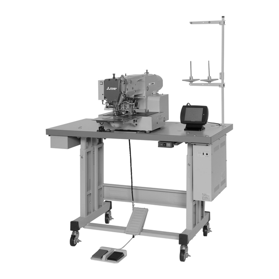
1. STRUCTURE OF THE SEWING MACHINE PLK-G1010 electronic pattern sewing machine consists of the following main parts. <10> <2> <1> <3> <5> <9> <11> <4> <8> <7> <6> <1>: Sewing machine head <2>: Main shaft motor <3>: Halt switch <4>: Control box <5>: Operation panel <6>: Work holder foot switch <7>: Start foot switch <8>... -
Page 8: Specification
2. SPECIFICATIONS Sewing area : X-direction (left/right) 100 mm, Y-direction (front / back) 100 mm Maximum sewing speed : 2,800 rpm Setting speed : 10 speed levels in 200 rpm to 2,800 rpm Stitch length : 0.1 to 20.0 mm Stitch type : Single needle lock stitch Maximum number of needles... -
Page 9: Installation
3. INSTALLATION CAUTION (1) Please have some specialists, who have enough experience for the sewing machine installations, install the sewing machine. (2) Please have a Qualified Electrician perform necessary electric wiring. (3) Please do not operate until the sewing machine is repaired when any damage or fault is found on the sewing machine at the installation. -
Page 10: Preparation Of The Steel Stand
(2) When fitting the caster to the steel stand, the steel stand has to be strong enough to withstand the weight and Vibration of the sewing machine. (3) If the steel stand is MITSUBISHI PLK-G1010 original, assemble the steel stand with the assembling instructions enclosed in the packing. -
Page 11: Installation Of The Oil Pan
3-6. Installation of the oil pan (1) Remove the oil pan A (No.1) from the accessory box then, set the oil bottle (No.2) to the oil pan A (No.1). (2) Put the oil pan at the position shown on the figure then, fix the oil pan with staples (No.3). (3) Set the damper cushions (No.4) to the table. -
Page 12: Installation Of The Tilting Detect Switch
<1>: Hinge shaft (two shafts) <3> <2>: Set screw (two screws) <9> <3>: Hinge (two hinges) <4>: Hinge rubber (two rubbers) <8> <5>: Support plate (two plates) <6>: Socket bolt (four bolts) <7>: Flat washer (four washers) <4> <8>: Head rest <2>... -
Page 13: Connection Of The Electric Cables
3-10. Connection of the electric cables CAUTION (1) Please make sure to ground the place where there is a mark. Failure to do so may cause electric shock and/or malfunction. (1) Connect the machine head and the control box with cables as shown on the figure. (2) Hold the dangling cables under the table with accessory tie holders (MB60A0420) and cord ties (MB60A0201). -
Page 14: Installation Of The Thread Stand
3-11. Installation of the thread stand (1) Assemble the parts (No.1 to No.11) of the thread stand as shown on the figure. (2) Fit the thread stand into the hole at the far right on the table stand with the nut (No.13) and the washers (No.12). -
Page 15: Installation Of The Spindle Motor
3-13. Installation of the spindle motor (1) If the spindle motor (No.1) has been removed from the machine for the adjustment or the like, fix the spindle motor as the procedure described below. (2) Set the pin (No.3) position of the bushing to the motor mark (No.2). (3) Adjust the clearance between the motor and the coupling (No.4). -
Page 16: Lubrication
4. LUBRICATION CAUTION (1) Please make sure to turn power switch off before lubricating. (2) Please pay attention that oil does not get on your skin or in your eyes as it may cause an inflammation. (3) Please make sure to keep oil out of the reach of children who may drink oil by mistake. [Notice] Please make sure to lubricate when operating for the first time after the installation. -
Page 17: Installation Of The Needle
5-2. Installation of the needle CAUTION (1) Please make sure to turn the power switch off before installing or replacing needles. (2) Please pay attention for the fingers not to be injured by the needle point. (1) Loosen the set screw (No.1) then, insert a new needle (No.2) until the needle head is reached the end of the hole of the needle bar (No.3). -
Page 18: Winding The Bobbin Thread
5-4. Winding the bobbin thread CAUTION (1) Please do not touch the rotating part during winding thread. Doing so may cause injury and/or the machine failure. [Notice] Please make sure to pull the upper thread out of the needle before winding the bobbin thread. (1) Route the thread as shown in the below figure then, wind the thread to the bobbin (No.1) in the direction of “a”... -
Page 19: Setting The Bobbin
5-5. Setting the bobbin (1) Insert a full Bobbin (No.2) into the bobbin case (No.1). (2) Pull out the bobbin thread (No.3) from the slit (No.4) and pass the thread through the thread hole (No.5). When the bobbin thread is pulled, the pin rotates in the arrow direction shown on the figure. If the pin starts rotating to the opposite direction, turn the bobbin over and reset the bobbin. -
Page 20: Sewing
6. SEWING CAUTION (1) Before starting the sewing, please make sure the position and the function of the halt switch. (2) Please do not touch the operating parts during sewing operation. (3) It is very dangerous to operate the sewing machine without safety guards (eye guards, belt covers, link covers, finger guards or the others). -
Page 21: Operation Of The Halt Switch
6-2. Operation of the halt switch <1> (1) If accidents such as a thread breakage, needle breakage and others happened during the sewing, press the halt switch immediately. The sewing machine stops instantly. (2) To cancel the halt state, press the halt switch again. (3) When continuing sewing, step on the grey foot switch to restart at the halted position. -
Page 22: Standard Adjustment
7. STANDARD ADJUSTMENT CAUTION (1) Please make sure to turn the power switch off before adjusting the sewing machine. (2) When adjusting the sewing machine with the power switch on, please be careful not to step on the foot switch by mistake. (3) Please be careful not to be injured by a sharp part such as the needle and the shuttle hook point. -
Page 23: Adjustment Of The Clearance Between The Shuttle Hook And The Needle
(6) If the shuttle hook point is not matched with the center line of the needle, loosen the driver (No.9) set screw (No.10) then, turn the shuttle hook and the driver for the adjustment. (7) For the needle class DP×5, move the needle bar to the position where the needle bar timing mark D is matched to the needle bar bushing bottom line then, carry out the same procedure as described above. -
Page 24: Adjustment Of The Shuttle Race Thread Guide
(No.3) moves back and forth. Adjust the clearance between the needle (No.4) and the driver (No.5) to be zero. <1>: Lower shaft bushing screw <4> <1> (two screws) <2>: Eccentric pin <3>: Lower shaft <4>: Needle <5>: Driver <3> <2> <5>... -
Page 25: Adjustment Of The Presser Foot Timing
7-6. Adjustment of the presser foot timing With changing the timing to sewing materials, the skip stitches can be prevented or the seam tightness can be improved. For example, the delay of the presser foot timing against the needle movement prevents the skip stitches especially to thin materials, and the advance of the presser foot timing can improve the seam tightness especially to thick materials. -
Page 26: Adjustment Of The Presser Foot Lift
7-7. Adjustment of the presser foot lift The presser foot lift can be returned factory default setting at 15mm as the procedure shown below. Also, if the presser foot does not move after changing the presser foot correction value and the stroke, carry out the procedure below. -
Page 27: Adjustment Of The Presser Foot Height Position
Hole A <6> <8> <7> <4> <3> 41mm <3>: Gauge <4>: Presser foot bar holder <6>: Presser foot drive motor <7>: Detector plate set screw <8>: Detector plate 7-8. Adjustment of the presser foot height position The height of presser foot can be returned factory default setting as the procedure shown below. (1) Turn the power switch on, and set the correction value at 0. -
Page 28: Adjustment Of The Presser Foot Walk During The Sewing
7-10. Adjustment of the presser foot walk during the sewing (1) The presser foot walk during the sewing can be adjusted with the walk at zero or the walk of 2 to 10mm. The walk at zero requires the exclusive parts (Option). Please feel free to contact the sewing machine stores. -
Page 29: Adjustment Of The Wiper
7-12. Adjustment of the wiper (1) Loosen the wiper setscrew (No.3) and adjust the wiper (No.1) to be positioned where the wiper (No.1) passes under the needle (No.2) point with a clearance of about 2mm right after the sewing machine stops at the needle upper position. -
Page 30: Adjustment Of The Trimmer Cam Follower
7-14. Adjustment of the trimmer cam follower (1) Turn the power switch off and remove the top cover. <5> <3> <1> (2) Loosen the arm set screw (No.3) to adjust the cam <4> follower (No.1) with a cam groove clearance of about 1mm between the cam follower and the trimmer cam (No.2). -
Page 31: Adjustment Of The Fixed Knife Position
7-16. Adjustment of the fixed knife position (1) Open the cylinder cover (No.1) and remove the ring-E type (No.4), which engages the movable knife (No.2) and the thread trimmer link (No.3). (2) Loosen the screw (No.5) then, remove the slide plate (No.6). (3) Adjust the fixed knife (No.7) position to be positioned for the blade edge to have the clearance 0.5mm from the edge of the needle plate (No.8), which is standard position. -
Page 32: Adjustment Of The Thread Tail After The Trimming
7-18. Adjustment of the thread tail after the trimming (1) Adjust the thread tail with the pre-tension (No.1). (2) When turning the nut clockwise, the thread tail becomes shorter. When turning the nut counterclockwise, the thread tail becomes <1> longer. <1>: Pre-tension 7-19. -
Page 33: Adjustment Of The X-Y Mechanical Home Position
7-21. Adjustment of the X-Y mechanical home position The mechanical home position (No.1) is fixed at the center of the sewing area as the factory default setting. The machine can be moved within the area (No.2) covered with diagonal lines. <2>... -
Page 34: Adjustment Of The Y Direction
change the mechanical home position. To use the sensor from the send returning, press [Home → → returning method since the second time returning] on the standard screen and set it ON. <3> <2> <1>: Detector plate X <2>: Detector <3>: Detector plate set screw <1>... -
Page 35: Maintenance
8. MAINTENANCE CAUTION (1) Please make sure to turn the power switch off before cleaning the sewing machine. (2) Please pay attention to that staining your skin or eyes with oil may cause an inflammation. 8-1. Cleaning (1) Remove the dust and the thread waste sticking the threading parts or the hooks area regularly. -
Page 36: Troubleshooting
9. TROUBLESHOOTING CAUTION (1) Please make sure to turn the power switch off before adjusting the sewing machine. (2) If the adjustment is required while the power switch on, do not step on the foot switch by mistake. Condition Cause Corrective action Reference Upper thread tension is too... - Page 37 Trimming is not Movable knife is at wrong Adjust position of movable 7-15 functioned. position. knife properly. Refer to the condition Skip stitching happens in “Frequent skip stitching trimming. happens”. Operation Trimming setting is off. Turn trimming setting on. panel section Upper thread tension is too Stitch forming is loose.
-
Page 38: Appendix
APPENDIX MEMO If the steel stand is not MITSUBISHI original, produce the parts with reference to the following drawings. The drawings show the measurements of original MITSUBISHI stand parts. <2> <1> <3> <6> <5> <7> <4> - 32 -... - Page 39 Stand part <1>···thickness 2mm Stand part <2>···thickness 2mm - 33 -...
- Page 40 Stand part <3>···thickness 2mm Stand part <4>···thickness 2mm Stand part <5>···thickness 2mm Stand part <6>···rubber thickness 2.5m Stand part <7>···permissible load more than 40kg (per wheel) - 34 -...
- Page 41 MITSUBISHI ELECTRIC CORPORATION FACTORY AUTOMATION SYSTEM GROUP 2-7-3, Marunouchi Chiyoda-ku Tokyo 100-8310, Japan Fax : +81-3-3218-6821 New publication, effective JAN.2009 Contents subject to change without notice...