
Related Manuals for BCM Advanced Research MX110HD


Summary of Contents for BCM Advanced Research MX110HD
- Page 1 MX110HD User’s Manual Ver 1.0 Intel® H110 Mini ITX Motherboard supports 14nm Intel® i7/i5/i3 generation Desktop Processors (Skylake / Kabylake Platform)
-
Page 2: Table Of Contents
Table of Contents MX110HD Motherboard Features .......................... 7 SPECIFICATIONS SUMMARY ..........................7 Block Diagram ..................................8 Processor ....................................8 INSTALLING THE CPU ............................10 INSTALLING THE CPU HEATSINK AND FAN ....................12 UNINSTALLING THE CPU HEATSINK AND FAN ....................14 System memory .................................. - Page 3 7.14 SATA header ................................30 7.15 PCIE X4 Slot ................................30 7.16 ATX 4-pin DC Power Input Header .......................... 31 BIOS Specification BIOS SETUP ..................................32 MAIN PAGE ..................................34 ADVANCED PAGE ................................35 TPM C ..............................37 OMPUTING ACPI S .................................
- Page 4 Safety Information Electrical safety To prevent electrical shock hazard, disconnect the power cable from the electrical outlet before relocating the system. When adding or removing devices to or from the system, ensure that the power cables for the devices are unplugged before the signal cables are connected. If possible, disconnect all power cables from the existing system before you add a device.
- Page 5 If a problem arises with your system and no solution can be obtained from the user’s manual, please contact your place of purchase or local distributor. Alternatively, please try the following help resources for further guidance. Visit the BCM Advanced Research website: http://www.BCMCOM.com 5 ...
- Page 6 Revision History Revision Revision History Date V1.0 First release version 2018/05 6 ...
-
Page 7: Mx110Hd Motherboard Features
1. MX110HD Motherboard Features This chapter briefly describes the Specifications of MX110HD board. Table 1 summarizes the major features of the Board. 1. 1 Specifications Summary Form Factor Low-profile Mini-ITX (20 millimeters [0.79 inches] x 170.18 millimeters [6.7 inches] x 170.18 millimeters [6.7 inches]) -
Page 8: Block Diagram
2. Block Diagram 3. Processor The board supports 6 generation Intel Core processors. Other processors may be supported in the future. This board supports processors with a maximum wattage of 65 W Thermal Design Power (TDP). NOTE This board has specific requirements for providing power to the processor. - Page 9 Your boxed Intel® Core™ i7/ i5/ i3 LGA1151 processor package should come with installation instructions for the CPU, fan and heatsink assembly. If the instructions in this section do not match the CPU documentation, follow the latter. Upon purchase of the motherboard, make sure that the PnP cap is on the socket and the socket pins are not bent.
-
Page 10: Installing The Cpu
3.1 Installing the CPU 1. Locate the CPU socket on the motherboard. Before installing the CPU, make sure that the socket box is facing towards you and the load lever is on your left. 2. Remove the PnP cap. 3. Press the load lever with your thumb (A), then move it to the left (B) until it is released from the retention tab. - Page 11 4. Position the CPU over the socket, making sure that the gold triangle is on the top-left corner of the socket then fit the socket alignment key into the CPU notch. Gold triangle CPU notch Alignment key 5. Pull back the load lever, then push the load lever (A) until it snaps into the retention tab.
-
Page 12: Installing The Cpu Heatsink And Fan
3. 2 Installing the CPU Heatsink and Fan Intel® Core™ i7/ i5/ i3 LGA1151 processor requires a specially designed heatsink and fan assembly to ensure optimum thermal condition and performance. Install the motherboard to the chassis before you install the CPU fan and heatsink assembly. When you buy a boxed Intel® Core™ i7/ i5/ i3 LGA1151 processor, the package includes the CPU fan and heatsink assembly. - Page 13 Make sure each fastener is oriented as shown, with the narrow groove directed outward. 2. Push down two fasteners at a time in a diagonal A sequence to secure the heatsink and fan assembly in place. B B A ...
-
Page 14: Uninstalling The Cpu Heatsink And Fan
3.3 Uninstalling the CPU Heatsink and Fan To uninstall the CPU heatsink and fan: 1. Disconnect the CPU fan cable from the connector on the motherboard. 2. Rotate each fastener counterclockwise 3. Pull up two fasteners at a time in a diagonal sequence to disengage the heatsink and fan assembly from the motherboard. A B B A 14 ... - Page 15 4. Carefully remove the heatsink and fan assembly from the motherboard. 5. Rotate each fastener clockwise to ensure correct orientation when reinstalling. 15 ...
-
Page 16: System Memory
System Memory The Desktop Board has t w o 260-pin DDR4 SO-DIMM sockets with gold-plated contacts. NOTE To be fully compliant with all applicable DDR SDRAM memory specifications, the board should be populated with DIMMs that support the Serial Presence Detect (SPD) data structure. -
Page 17: Installing A Ddr4 Sodimm
4.2 Installing a DDR4 SODIMM Make sure to unplug the power supply before adding or removing DIMMs or other system components. Failure to do so may cause severe damage to both the motherboard and the components. 1. Locate the SODIMM socket on the board. 2. Hold two edges of the SODIMM module carefully, and keep away of touching its connectors. 3. Align the notch key on the module with the rib on the slot. 4. Firmly press the modules into the socket which will automatically snap into the mounting notch. Do not force the SODIMM module in with extra force as the DIMM module only fits in one direction. 5. Press down until SODIMM module Mounting Notch clicks in. A DDR4 SODIMM is keyed with a notch so that it fits in only one direction. DO NOT force a SODIMM into a socket to avoid damaging the DIMM. The DDR4 SODIMM sockets do not support DDR3 SODIMMs. DO NOT install DDR3 SODIMMs to the DDR4 SODIMM socket. 17 ... -
Page 18: Removing A Ddr4 Sodimm
4.3 Removing a DDR4 SODIMM 1. Press the two ejector tabs on the slot outward simultaneously, and then pull out the DIMM module. Support the DIMM lightly with your fingers when pressing the ejector tabs. The DIMM might get damaged when it flips out with extra force. 18 ... -
Page 19: Rear Panel Connector Placement
5. Rear Panel connector Placement Item Function Description DC Input DC power IN 24V only USB 3.0 USB 3.0 USB 3.0 function and compatible with USB 2.0 DP out Display port Display port 20P connector HD out HDMI connector High Definition Media Interface 19P connector This port allows Gigabit connection to a Local Area RJ45... -
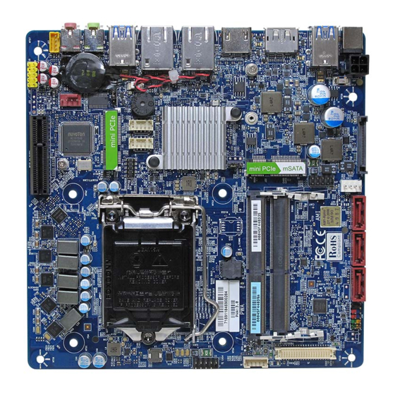
Page 20: On-Board I/O Placement
On-Board I/O placement Item Description Front panel connector SATA III signal connector CPU fan header Dual USB2.0 header SATA power connector DC Power header(12~24V) mSATA/ Mini PCIE slot CMOS jumper Serial header Serial header AT/ATX jumper AMP SPK connector Front Audio System fan header PCI Express X4 slot Mini PCIE slot (Half Length) Dual USB2.0 header Backlight (Brightness control) LVDS connector 20 ... -
Page 21: Internal Header
Internal Headers 7 . 1 F r o n t I O Figure 1 : Front SW/LEDs header pin-out Signal Signal HD_LED+ PWR_LED+ HD_LED` PWR_LED‐ PWR_BTN RESET [KEY] Table 3: Front SW/LEDs header signals 7 . 2 LV D S H e a d e r Figure 2: LVDS Connector Signal Signal... -
Page 22: Lvds Inverter Header
LVDS_A3+ LVDS_A2+ LVDS_A3‐ LVDS_A2‐ LVDS_B1+ LVDS_B0+ LVDS_B1‐ LVDS_B0‐ LVDS_B3+ LVDS_B2+ LVDS_B3‐ LVDS_B2‐ LVDS_B_CLK+ LVDS_A_CLK+ LVDS_B_CLK‐ LVDS_A_CLK‐ +12V +12V Table 4: 40-pin LVDS data header pin-out reference 7 . 3 LV D S I nv e r t e r p o w e r H e a d e r Figure 3: LVDS inverter power header pin-out Signal Name Description... -
Page 23: Usb 2.0 Header
7 . 4 U S B 2 . 0 H e a d e r Figure 4: Dual USB2.0 pin-out Signal Signal 5V_USB 5V_USB Data (negative) Data (negative) Data (positive) Data (positive) Ground Ground Key (no pin) No Connect Table 6 Dual USB 2.0 Header 7 . -
Page 24: Internal Speaker Header
7 . 6 I n t e r n a l s p e a ke r H e a d e r Figure 6: Internal speaker pin-out Signal Name Front_L- Front_L+ Front_R+ Front_R- Internal header Table 8: signals ... -
Page 25: Fan Header
7 . 8 Fa n H e a d e r Signal Ground +12V CPU_FAN_TACH Figure 8 Processor fan header pin-out CPU_FAN_CTRL Table 10 fan header signals 7 . 9 C l e a r C M O S H e a d e r Normal (Default) ... -
Page 26: Half Length Mini Pcie Connector
ATX MODE (Default) AT MODE AT Mode: When DC-In power is applied, system will power on automatically. ATX Mode: Power button is required to power on system. 7 . 1 1 H a l f l e n g t h M i n i P C I e c o n n e c t o r ... - Page 27 CLKREQ_WLAN- CLKREQ Ground Ground PCH_100M_WIRELESS- CLOCK(negative) PCH_100M_WIRELESS CLOCK(positive) Ground Ground Ground Ground WLAN_DISABLE- DAC output Ground Ground PCIE_RST- Reset PCIe_WIRELESS_RX- Receive(negative) 3VSB Power PCIe_WIRELESS_RX+ Receive(positive) Ground Ground Ground Ground V_1P5 Power Ground Ground SMB_CLK_RESUME SMbus CLOCK PCIe_WIRELESS_TX- Transmit(negative) SMB_DATA_RESUME SMbus DATA PCIe_WIRELESS_TX+ Transmit(positive)
-
Page 28: Full Length Mini Pcie Connector
3VSB Power GND1 Ground Ground GND2 Ground Ground For WLAN signals Table 11: MiniPCIe slot 7 . 1 2 F u l l l e n g t h M i n i P C I e c o n n e c t o r Figure 11: MiniPCIe slot for mSATA/ WLAN card pin-out Signal Name Description... -
Page 29: Sata Power Header
PCIe_TVBD_RX-_R Receive(negative) 3VSB Power PCIe_TVBD_RX+_R Receive(positive) Ground Ground Ground Ground V_1P5 Power Ground Ground SMB_CLK_MAIN SMbus CLOCK PCIe_TVBD_TX-_R Transmit(negative) SMB_DATA_MAIN SMbus DATA PCIe_TVBD_TX+_R Transmit(positive) Ground Ground Ground Ground USB_PCH_DN9 DATA(negative) Ground Ground USB_PCH_DP9 DATA(Positive) 3VSB Power Ground Ground 3VSB Power Ground Ground... -
Page 30: Sata Header
VCC3 Power VCC3 Power VCC3 Power Ground Ground Ground Power Power Power Ground Ground +12V Power +12V Power +12V Power Table 13: SATA Power Cable signals 7 . 1 4 S ATA H e a d e r Figure 13: SATA Header pin-out Signal Name Description... -
Page 31: Pcie X4 Slot
Ground Table 14: SATA Header signals 7 . 1 5 P C I E x p re s s E x p a n s i o n S l o t s PCI Express x4 slot must be compatible with PCI Express x4 and x1 add‐on cards. Slot power capability must comply with 25W requirement as defined in the PCI Express Card Electromechanical 2.0 Specification. Routing WAKE# to ... -
Page 32: Bios Setup
BIOS Setup This motherboard supports a programmable firmware chip that you can update using the provided utility. Use the BIOS Setup program when you are installing a motherboard, reconfiguring your system, or prompted to “Run Setup.” This section explains how to configure your system using this utility. - Page 33 1.1. Legend Box The keys in the legend bar allow you to navigate through the various setup menus Key(s) Function Description →← Select Screen ↑↓ Select Item Enter Select Change Opt. +/- General Help Previous Values Optimal Defaults Save and Exit Exit 1.2 List Box This box appears only in the opening screen.
-
Page 34: Main Page
Item help BIOS Information BIOS Vender American Megatrends Core Version 5.11 Compliancy UEFI 2.4 ; PI 1.3 MX110HD (71591) VX.XX BIOS Version Build Date XX/XX/XXXX →←: Select Screen Processor Information ↑↓: Select Item Intel(R) CORE(TM) i5-6600 CPU @ 3.30GHZ Enter: Select +/- : Change Opt. -
Page 35: Advanced Page
Field Name Memory Frequency Value Display the installed memory frequency. Comment This field is not selectable. There is no help text associated with it. Field Name System Date Default Value [xxx, mm dd yyyy] Possible Value [xxx, xx:xx:xxxx] Help Set the Date. - Page 36 Field Name ACPI Settings Help System ACPI Parameters. Comment Press Enter when selected to go into the associated Sub-Menu. Field Name SMART Settings Help System SMART Settings. Comment Press Enter when selected to go into the associated Sub-Menu. Field Name Hardware Monitor Help Monitor hardware status.
-
Page 37: Acpi Settings
3.1 TPM Settings Main Advanced Chipset Security Boot Save & Exit Item help TPM Settings Security Device Support [Disabled] →←: Select Screen ↑↓: Select Item Pending operation [None] Enter: Select TPM2.0 UEFI Spec Version [TCG_2] +/- : Change Opt F1: General Help F2: Previous Values F3: Restore Legacy Defaults... -
Page 38: Smart Settings
Enable Hibernation [Enabled] Enter: Select ACPI Sleep State [S3 (Suspend to RAM)] +/- : Change Opt F1: General Help F2: Previous Values F3: Restore Legacy Defaults F4: Save & Reset ESC: Exit Version 2.17.1254. Copyright (C) 2015 American Megatrends, Inc. Field Name Enable ACPI Auto Configuration Default Value... - Page 39 Version 2.17.1254. Copyright (C) 2015 American Megatrends, Inc. Field Name SMART Self Test Default Value [Disabled] Possible Value Disabled Enabled Help Run SMART Self Test on all HDDs during POST. 3.4 Super IO Configuration Main Advanced Chipset Security Boot Save &...
-
Page 40: 1-3.4.2 Serial Port 1,2 Configuration
3.4.1 Serial Port 1 Configuration Main Advanced Chipset Security Boot Save & Exit Item help Serial Port 1 Configuration Serial Port [Enabled] →←: Select Screen Device Settings IO=3F8h; IRQ=4; ↑↓: Select Item Enter: Select Change Settings [Auto] +/- : Change Opt F1: General Help F2: Previous Values F3: Restore Legacy Defaults... - Page 41 3.4.2 Serial Port 2 Configuration Main Advanced Chipset Security Boot Save & Exit Item help Serial Port 2 Configuration Serial Port [Enabled] →←: Select Screen Device Settings IO=2F8h; IRQ=3; ↑↓: Select Item Enter: Select Change Settings [Auto] +/- : Change Opt F1: General Help F2: Previous Values F3: Restore Legacy Defaults...
- Page 42 3.5 Hardware Monitor Main Advanced Chipset Security Boot Save & Exit Pc Health Status Item help CPU VR temperature Memory temperature CPU temperature System Fan Speed : N/A CPU Fan Speed : N/A →←: Select Screen CPU Fan Control [Manual Mode] ↑↓: Select Item Target Fan Output...
- Page 43 3.6 S5 RTC Wake Settings Main Advanced Chipset Boot Security Save & Exit Wake system with Fixed Time [Disable] Item help Wake up hour Wake up minute →←: Select Screen Wake up second ↑↓: Select Item Enter: Select +/- : Change Opt F1: General Help F2: Previous Values F3: Restore Legacy Defaults...
-
Page 44: S5 Rtc Wake Settings
3.7 CPU Configuration Main Advanced Chipset Security Boot Save & Exit CPU Configuration Item help Intel(R) Core(TM) CPU [CPU NAME] @ [CPU Freq.] GHz CPU Signature 506E3 Microcode Patch Max CPU Speed 3300 MHz Min CPU Speed 800 MHz CPU Speed 3600 MHz Processor Cores... - Page 45 Comment This field is not selectable. There is no help text associated with it. Field Name Max CPU Speed Default Value Displays the Max CPU Speed Comment This field is not selectable. There is no help text associated with it. Field Name Min CPU Speed Default Value...
- Page 46 Comment This field is not selectable. There is no help text associated with it. Field Name Hyper-threading (Hided if HT not Supported) Default Value [Enabled] Possible Value Enabled Disabled Help Enabled for Windows XP and Linux (OS optimized for Hyper-Threading Technology) and Disabled for other OS (OS not optimized for Hyper-Threading Technology).
-
Page 47: Sata Configuration
Possible Value Enabled Disabled Help Enable/Disable C1E. When enabled, CPU will switch to minimum speed when all cores enter C-State. Field Name Package C state limit Default Value [C3] Possible Value C0/C1 AUTO Help Package C State limit 3.8 SATA Configuration Main Advanced Chipset... - Page 48 3.9 Network Stack Configuration Main Advanced Chipset Security Boot Save & Exit Item help Network stack [Disabled] Ipv4 PXE Support [Enabled] Ipv6 PXE Support [Enabled] →←: Select Screen ↑↓: Select Item Enter: Select +/- : Change Opt F1: General Help F2: Previous Values F3: Restore Legacy Defaults F4: Save &...
-
Page 49: Network
3.10 CSM Configuration Main Advanced Chipset Security Boot Save & Exit Compatibility Support Module Configuration Item help CSM Support [Enabled] CSM16 Module Version 07.79 Option Rom execution →←: Select Screen ↑↓: Select Item Network [DO not launch] Enter: Select Storage [Legacy] +/- : Change Opt... - Page 50 Field Name Video Default Value [Legacy] (Restore Legacy Default) [UEFI] (Restore UEFI Default) Possible Value UEFI Legacy Help Controls the execution of UEFI and Legacy Video OpROM. Field Name Other PCI devices Default Value [Legacy] (Restore Legacy Default) [UEFI] (Restore UEFI Default) Possible Value DO not launch...
-
Page 51: Usb Configuration
3.11 USB Configuration Main Advanced Chipset Security Boot Save & Exit USB Configuration Item help USB Devices: 1 Keyboard, 1 Mouse, 2 Hubs →←: Select Screen Legacy USB Support [Enabled] ↑↓: Select Item XHCI Hand-off [Disabled] Enter: Select USB Mass Storage Driver Support [Enabled] +/- : Change Opt Port 60/64 Emulation... -
Page 52: Chipset Page
Chipset Page Main Advanced Chipset Security Boot Save & Exit ►System Agent (SA) Configuration Item help ►PCH-IO Configuration →←: Select Screen ↑↓: Select Item Enter: Select +/- : Change Opt F1: General Help F2: Previous Values F3: Restore Legacy Defaults F4: Save &... -
Page 53: System Agent (Sa) Configuration
4.1 System Agent (SA) Configuration Main Advanced Chipset Security Boot Save & Exit ►Graphics Configuration Item help ►PEG Port Configuration ►Memory Configuration →←: Select Screen ↑↓: Select Item Enter: Select +/- : Change Opt F1: General Help F2: Previous Values F3: Restore Legacy Defaults F4: Save &... -
Page 54: Graphics Configuration
4.1.1 Graphics Configuration Main Advanced Chipset Security Boot Save & Exit Graphics Configuration Item help Primary Display [Auto] →←: Select Screen Internal Graphics [Auto] ↑↓: Select Item GTT Size [8MB] Enter: Select Aperture Size [256MB] +/- : Change Opt DVMT Pre-Allocated [32M] F1: General Help... -
Page 55: Lcd Control
Field Name DVMT Total Gfx Mem Default Value [128M] Possible Value 128MB / 256MB / MAX Help Select DVMT5.0 Total Graphic Memory size used by the Internal Graphics Device. Field Name LCD Control Help LCD Control Comment Press Enter when selected to go into the associated Sub-Menu. 4.1.1.1 LCD Control Main Advanced Chipset... -
Page 56: Peg Port Configuration
1680x1050 24bit Dual Channel 1920x1200 24bit Dual Channel 1440x900 24bit Dual Channel 1600x900 24bit Dual Channel 1024x768 24bit Single Channel 1280x800 18bit Single Channel 1920x1080 24bit Dual Channel 2048x1536 24bit Dual Channel Help Select LCD panel used by Internal Graphics Device by selecting the appropriate setup item. -
Page 57: Memory Configuration
4.1.3 Memory Configuration Main Advanced Chipset Boot Security Save & Exit Memory Information Item help Memory Frequency 2133 Mhz →←: Select Screen Total Memory 8192 MB ↑↓: Select Item DIMM#0 8192 MB Enter: Select DIMM#1 Not Present +/- : Change Opt F1: General Help F2: Previous Values F3: Restore Legacy Defaults... -
Page 58: Pch-Io Configuration
PCH-IO Configuration Main Advanced Chipset Security Boot Save & Exit Item help ►HD Audio Configuration →←: Select Screen PCH LAN Controller [Enabled] ↑↓: Select Item DeepSx Power Policies [Disabled] Enter: Select Wake on LAN [Enabled] +/- : Change Opt State After G3 [S5 State] F1: General Help... -
Page 59: Hd Audio Configuration
4.2.1 HD Audio Configuration Main Advanced Chipset Boot Security Save & Exit HD Audio Configuration Item help HD Audio [Auto] →←: Select Screen ↑↓: Select Item Enter: Select +/- : Change Opt F1: General Help F2: Previous Values F3: Restore Legacy Defaults F4: Save &... -
Page 60: Security Page
Security Page Main Advanced Chipset Security Boot Save & Exit Password Description Item help If Only the Administrator's password is set, then this only limits access to Setup and is only asked for when entering Setup. If ONLY the User’s password is set, then this is a power on password and must be entered to boot or enter Setup. - Page 61 Comment Press Enter when selected to go into the associated Sub-Menu. Field Name Secure Boot menu Help Customizable Secure Boot settings Comment Press Enter when selected to go into the associated Sub-Menu. 61 ...
-
Page 62: Hdd Security
5.1 HDD Security Main Advanced Chipset Security Boot Save & Exit HDD Password Description : Item help Allows Access to Set, Modify and Clear HardDisk User and Master Passwords. User Password need to be installed for Enabling Security. Master Password can be Modified only when successfully unlocked with Master Password in POST. -
Page 63: Secure Boot Mode
5.2 Secure Boot Mode Main Advanced Chipset Security Boot Save & Exit Item help System Mode Setup Secure Boot Not Active →←: Select Screen Vendor Keys Not Active ↑↓: Select Item Enter: Select Secure Boot [Enabled] +/- : Change Opt Secure Boot Mode [Standard] F1: General Help... -
Page 64: Key Management
5.3 Key Management Main Advanced Chipset Security Boot Save & Exit Provision Factory Default keys [Disabled] Item help ► Enroll All Factory Default Keys →←: Select Screen ► Save All Secure Boot Variables ↑↓: Select Item Enter: Select Secure Boot variable Size Key# Key source... - Page 65 a)EFI_SIGNATURE_LIST, b)EFI_CERT_X509 (DER encoded), c)EFI_CERT_RSA2048 (bin), d)EFI_CERT_SHA256 (bin) 2.Authenticated UEFI Variable Key source: Default, Custom, Mixed (*) modified through Setup menu comment Press Enter when selected to go into the associated Sub-Menu. Field Name Authorized Signature Default Value Size:0, Key#:0, Key source: * Help Enroll Factory Default Keys or load from a file formatted as: 1.Public Key Certificate in:...
-
Page 66: Boot Page
Boot Page Main Advanced Chipset Security Boot Save & Exit Boot Configuration Item help Setup Prompt Timeout Bootup NumLock State [On] Quiet Boot [Disabled] Custom Logo [Disabled] Driver Option Priorities Boot mode select [LEGACY] FIXED BOOT ORDER Priorities Boot Option #1 [Hard Disk] →←: Select Screen Boot Option #2... - Page 67 Default Value [Disabled] Possible Value Enabled Disabled Help Enables or Disables Quiet Boot option Field Name Custom Logo Default Value [Disabled] Possible Value Enabled Disabled Help Enables or Disables Custom Logo option Field Name Boot mode select Default Value [LEGACY] (Restore Legacy Default) [UEFI]...
- Page 68 Default Value [USB Lan] Possible Value Hard Disk, CD/DVD, USB Hard Disk, USB CD/DVD, USB Key, USB Floppy , USB Lan, Network, Disabled Help Sets the system boot order Field Name Boot Option #8 Default Value [Network] Possible Value Hard Disk, CD/DVD, USB Hard Disk, USB CD/DVD, USB Key, USB Floppy , USB Lan, Network, Disabled Help...
-
Page 69: Drive Bbs Priorities
6.1 (List Boot Device Type) Drive BBS Priorities Main Advanced Chipset Security Boot Save & Exit Boot Option #1 [Boot Device Name 1] Item help Boot Option #2 [Boot Device Name 2] →←: Select Screen ↑↓: Select Item Enter: Select +/- : Change Opt F1: General Help F2: Previous Values... -
Page 70: Boot
Save & Exit Page Main Advanced Chipset Security Boot Save & Exit Save Options Item help Discard Changes and Exit Save Changes and Reset Discard Changes and Reset →←: Select Screen Default Options ↑↓: Select Item Restore Legacy Defaults Enter: Select Restore UEFI Defaults +/- : Change Opt... - Page 71 Help Restore the User Defaults to all the setup options. Comment Field Name Launch EFI Shell from filesystem device Help Attempts to launch EFI Shell application (Shell.efi) from one of the available filesystem devices Comment 71 ...
Need help?
Do you have a question about the MX110HD and is the answer not in the manual?
Questions and answers