
Related Manuals for Torqeedo Ultralight 403 A


Summary of Contents for Torqeedo Ultralight 403 A
- Page 1 Ultralight 403 A/AC 1103 AC Translation of the original operating instructions Deutsch English...
- Page 2 Foreword Foreword Dear Customer, We are delighted that you have chosen our motor. Your Torqeedo Ultralight system delivers cutting-edge drive technology and efficiency. It has been designed and manufactured with the utmost care and with a special fo- cus on convenience, user-friendliness and safety, and has been extensively tested before delivery.
-
Page 3: Table Of Contents
Contents Contents Introduction............... 69 6.2 Installation of the drive to the kayak/boat..... 84 1.1 General information on the instructions......69 6.2.1 Top control cords............84 1.2 Explanation of symbols............69 6.2.2 Bottom control cords..........87 1.3 Layout of the safety information........70 6.2.3 Inserting the motion link in the bracket.... - Page 4 Contents 7.1 Emergency Stop................. 102 13 Accessories................. 120 7.2 Travel mode................. 103 14 Disposal and environment..........122 7.2.1 Starting a trip............... 103 14.1 Disposal of waste electrical and electronic equipment............... 122 7.2.2 Forward/reverse motion.......... 103 14.2 Disposal of batteries..............122 7.2.3 Steering................
-
Page 5: Introduction
Ensure that you always use the most recent version of the instructions. The cur- rent version of the instructions can be downloaded on the Internet from website www.torqeedo.com under the "Service Centre" tab. Software updates may result in changes to the instructions. -
Page 6: Layout Of The Safety Information
Introduction Layout of the safety information About this operating manual In these instructions, safety information is presented using standardised represen- Instructions tation and symbols. Comply with the relevant information. The hazard classes ex- Actions that require several steps are presented in a numbered list. Complete the plained are used according to the likelihood of occurrence and the severity of the steps in the correct order. -
Page 7: Name Plate
1405-00 Ultralight 403 AC S.Nr. JJKKHZZZVTTT-XXXXX S.Nr. JJKKHZZZVTTT-XXXXX 320h/26.6 V/ 11Ah 320h/26.6 V Manufactured 2016 by Torqeedo GmbH Manufactured 2016 by Torqeedo GmbH Friedrichshafener Str r . 4a, D-82205 Gilching Friedrichshafener Str r . 4a, D-82205 Gilching Fig. 42: Ultralight name plate Fig. -
Page 8: Registering The Device
Registering the device Registering the device You can register your Ultralight system using the serial numbers; see Chapter 1.5, "Name plate". You can carry out registration free-of-charge via the Torqeedo web- site: https://www.torqeedo.com/de/service-center/device-registration.html. page 72 / 128... -
Page 9: Equipment And Controls
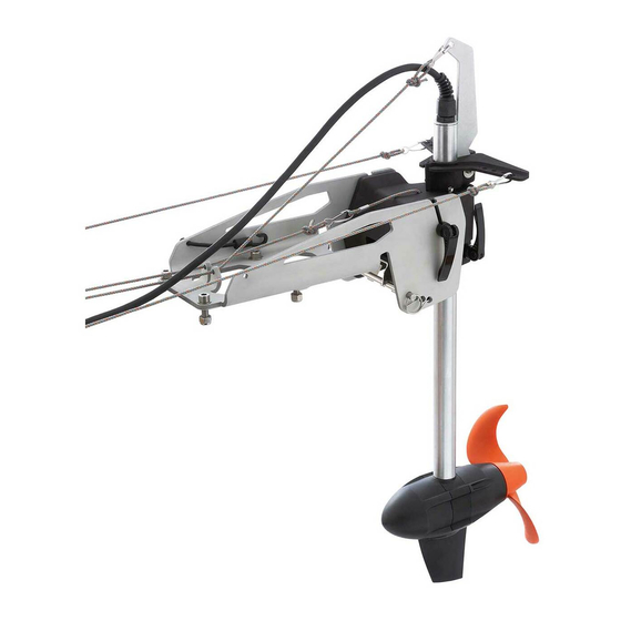
Equipment and controls Scope of delivery Overview of controls and components The complete scope of delivery of your Torqeedo Ultralight system includes the fol- lowing components: Motor unit with shaft, pylon, propeller and 1.90 m (75 in) connection cable Accelerator lever with integrated display... - Page 10 Equipment and controls Ultralight Fig. 47: Overview of components Swing arm Battery connection Pylon Control triangle with clamping ring 10 Swivel cord 11 Cord for reverse fixing Motion link with quick clamp 12 Rubber expander Clamping lever Shaft 13 Bracket with trim mechanism Propeller page 74 / 128...
-
Page 11: Technical Data
Technical data Technical data Type designation Ultralight Ultralight Ultralight Type designation Ultralight Ultralight Ultralight 403 A 403 AC 1103 AC 403 A 403 AC 1103 AC Max. input power 400 W 400 W 1100 W Standard propeller v10/p350 v10/p350 v10/p1100 (v = speed in km/h) Max. -
Page 12: Lithium-Ion Battery
Technical data Lithium-ion battery Specification 320 Wh battery 915 Wh battery Capacity 320 Wh 915 Wh Operating/storage temperature -20° C to +60° C -20° C to +60° C (-4° F to 140° F) (-4° F to 140° F) Storage temperature for stor- 5-15 °C (40-60 °F) 5-15 °C (40-60 °F) age >3 months... -
Page 13: Safety
Safety Safety Safety features Safety features Function Magnetic kill switch Disconnects the energy supply immediately, and switches off the Ultralight system. The propeller then comes to a stop. Electronic Ensures that the Ultralight system can be switched on accelerator lever only in the neutral position, in order to prevent unin- tentional start-up of the Ultralight system. -
Page 14: General Safety Provisions
Failure to comply with these instructions can result in personal injury or material 5.2.3 Foreseeable misuse damage. Torqeedo accepts no liability for damage caused by actions which are Use other than, or going beyond, that defined in Chapter 5.2.2, "Intended use" is contrary to these instructions. -
Page 15: Before Use
Safety 5.2.4 Before use Protect the battery from mechanical damage. In case of damage to the battery WA R N I N G ! housing, do not use or charge the battery any more. Danger to life from a boat which is not manoeuvrable! Always charge the battery under the supervision of an adult and on a fire-proof This can result in severe physical injuries or death. -
Page 16: General Safety Information
In case the battery is submerged more than one meter under water for a This can result in severe physical injuries or death. short period of time, contact Torqeedo Service and do not attempt to recov- Before starting a trip, inform yourself of the intended travel area, and take er the battery. - Page 17 Safety WA R N I N G ! C AUT I ON! Mechanical hazard from rotating components! Danger of crushing if motor tilts. This can result in severe physical injuries or death. Minor or moderately severe physical injuries may result. Do not wear jewellery or loose clothing in the vicinity of the drive shaft or When tilting the motor, ensure that no-one is present in the vicinity of the the propeller.
-
Page 18: Start-Up
Start-up Start-up Installation of the bracket with trim mechanism Threaded inserts on the kayak/boat AD VI C E The bracket with trim mechanism must be used only in combination with the Ultralight 403 or 1103 pylons. There are three fixing possibilities for the bracket with trim mechanism: Threaded inserts on the kayak/boat Adapter plate Unthreaded drill holes on the kayak/boat (drill template) - Page 19 Start-up Adapter plate Unthreaded drill holes on the kayak/boat (drill template) Fig. 49: Installation of adapter plate Fig. 50: Installation using a drill template 1. Place the bracket with trim mechanism flush on the adapter plate. 1. Place the drill template in a suitable location (flat, central) on the end of the kayak/boat.
-
Page 20: Installation Of The Drive To The Kayak/Boat
Start-up 6.2.1 Top control cords 4. Fix the bracket with trim mechanism using four M8 screws, eight washers (four on top, four on the bottom) and four nuts over the drill holes, and tighten to a torque of 16 Nm (140 lb/in). 5. - Page 21 Start-up If the control cords run on the top of the kayak/boat, or they run above the pivot point of the bracket out of the sleeve of the kayak, then proceed as follows: Fig. 52: Control triangle and swing arm Swing arm M5 screw Fig.
- Page 22 Start-up 6. Slide the control triangle (1), the motion link with quick clamp (3) and the clamp- ing ring (5) together. 7. Place the combination of control triangle (1), motion link with quick clamp (3) and clamping ring (5) in the desired position. The position of the motion link with quick clamp (3) determines the height of the motor.
-
Page 23: Bottom Control Cords
Start-up 6.2.2 Bottom control cords If the control cords come out of the skin of the kayak under the motion link, or if they come directly out of the stern, proceed as follows: Fig. 54: Bottom control cords Fig. 55: Quick clamp and clamping unit control triangle Control triangle Quick clamp... - Page 24 Start-up Fig. 56: Clamping ring and swing arm Fig. 57: Combination of clamping ring, motion link and control triangle Swing arm M5 screw Control triangle Swing arm 10 Clamping ring 10 Clamping ring Motion link with quick clamp Washers Control triangle clamping unit 11 Motor unit shaft 2.
-
Page 25: Inserting The Motion Link In The Bracket
Start-up 6.2.3 Inserting the motion link in the bracket 6. Push the control clamping ring (10), the motion link with quick clamp (2) and the control triangle (1) together. 7. Place the combination of control triangle (10), motion link with quick clamp (2) and clamping ring (1) in the desired position. -
Page 26: Setting For Optimum Depth Of Water
Start-up Setting for optimum depth of water Attaching the steering The highest point of the propeller must be at least 5 cm below the surface of the wa- ter. 1. Release the M5 screw on the clamping ring/control triangle. 2. Release the quick clamp on the clamping ring/control triangle. 3. -
Page 27: Connecting The Cords
Start-up Overview of cords AD VI C E Bend the small fixing pin (1) upwards if it is not seated properly. Connecting the cords AD VI C E The cords must not pass over sharp edges or pointed objects. The cords must move freely and should be diverted by as few points as pos- sible on the kayak/boat. - Page 28 Start-up Preparation of the swivel cords/control cords and cord for reverse fixing Fig. 62: Cord with carabiner Fig. 61: Clamp Cord Clamp Screws with counter-plate Carabiner 1. Fix the clamp (4) using screws and counter-plates (5) in the rail on the starboard 4.
- Page 29 Start-up Connecting the control cords 1. Using the carabiner (8), fix the first control cord in a suitable drill hole (9) on the control triangle. AD VI C E 2. Using the carabiner (8), fix the second control cord in the same drill hole (9) on The control cords are not included in the delivery, and you need to fit them the opposite side.
- Page 30 Start-up Cord for reverse fixing For the model 1103 AC you must thread the swivel cord (11) through the cord pull, see "Fig. 65: Cord pull 1103 AC models". 15 16 3. Fix the black ball handle on the front end of the swivel cord (11). AD VI C E For the model 1103 AC you must install a pull cord (included in scope of deliv- ery) for tilting using a swivel cord.
-
Page 31: Trimming The Motor
Start-up Trimming the motor In order to position the motor optimally relative to the water surface, several steps are required: 1. Tilt the motor upwards, see Chapter 7.4, "Tilting the motor". 2. Remove the securing cotter pin (2) of the trim rod (1), and pull the trim rod (1) out of the transom bracket. -
Page 32: Battery Power
Start-up Battery power AD VI C E The charger unit connection must be sealed off using the provided cap if charg- ing is not taking place. AD VI C E The battery and power supply unit must not be covered during the charging process. -
Page 33: Connecting Cable To Lithium Ion Battery With Integrated Gps Receiver
Charge using a DC power supply in the range of 9.5 V to 50 V. The DC power supply must be able to provide at least 4 A. Use the Torqeedo 12/24 V charging cable (item number 1128-00) for charging. page 97 / 128... -
Page 34: Start-Up Of The On-Board Computer
Start-up Start-up of the on-board computer 6.9.1 Displays and symbols Fig. 69: Multifunction display Fig. 70: Overview of multifunction display The accelerator lever is fitted with an integrated display or onboard computer and Battery charge state in percent Speed over the ground three buttons. - Page 35 Start-up Drive Displayed when the battery capacity is <30 %. slowly (1) Charging (2) Displayed during charging. The integrated GPS module searches for satellite signals in order to searching (3) calculate speed. If no GPS signal is received, then the second field of the display continuously shows the "Remaining run time at cur- rent speed"...
-
Page 36: Display Settings
Start-up 6.9.2 Display settings In the Set-up menu, you can select the units to be displayed on screen (in orange). 1. Press the Set-up button in order to access the Set-up menu. 2. Use the CAL button to set the unit in which the remaining range is to be dis- played. -
Page 37: Operation
Operation Operation WA R N I N G ! Danger to life from a boat which is not manoeuvrable! This can result in severe physical injuries or death. Before starting a trip, inform yourself of the intended travel area, and take note of the predicted weather and water conditions. -
Page 38: Emergency Stop
Operation Emergency Stop There are two different options for stopping the Ultralight system rapidly: Place the accelerator lever in the neutral position. DA N G ER ! Pull off the magnetic kill switch. Risk of death if the Emergency Stop is not triggered! ADV I C E Death or severe physical injuries may result. -
Page 39: Travel Mode
Operation Travel mode 7.2.1 Starting a trip 7.2.2 Forward/reverse motion AD VI C E If there is visible damage to components or cables, do not turn on the Ultralight system. Ensure that all people on board wear a life jacket. Before starting, attach the lanyard of the Emergency Stop to your wrist or life jacket. -
Page 40: Steering
Operation Block for reversing 7.2.3 Steering AD VI C E 1. Pull the cord with the red ball handle until the reversing block engages. Never actuate the control cords at the same time, since this can lead to material 2. Ensure that the motor unit is vertical to the water surface and is not tilted. damage. -
Page 41: Tilting The Motor
Operation Tilting the motor C AUT I O N! Danger of crushing if motor tilts. Minor or moderately severe physical injuries may result. When tilting the motor, ensure that no-one is present in the vicinity of the motor. Do not reach into the mechanical parts when tilting the motor. C AUT I O N! Material damage from falling motor unit! Material damage can result. - Page 42 Operation Park position 4. Insert the heel of the control triangle/clamping ring into the recess provided be- tween the guide hole, the swivel cord, and the guide hole of the cord for reverse AD VI C E fixing. The park position can be used only for the model 403 A/AC. 5.
-
Page 43: Removal
Removal Removal C AUT I O N! Damage to the boat and system if the motor is removed when the boat is in the water! Material damage can result. Install/remove the motor only on land. Bracket with trim mechanism Motor unit with motion link Quick clamp 1. - Page 44 Removal 4. Release all cords. 5. Release the quick clamp (2) on the motion link, and remove the motor unit with motion link (3) from the bracket (1). page 108 / 128...
-
Page 45: Towing The Kayak/Boat
Towing the kayak/boat Towing the kayak/boat When the boat is towed, the motor must always be removed, see Chapter 8, "Re- moval". Comply with the applicable national regulations for towing kayaks/boats. page 109 / 128... -
Page 46: Error Messages
Stator excess temperature (motor overheated) After waiting for a short period (approx. ten minutes), the motor can be operated slowly again. Contact Torqeedo Service. Motor tilted in operation Motor can continue to run after tilting down and switching off and on. - Page 47 Recalibrate; see "E21". Communication error with motor Check the cables and the plug connections of the data cables. If necessary, contact Torqeedo Service and tell them the error code. Communication error for accelerator lever Check the plug connections of the data cables.
- Page 48 If the error arises while or after charging the battery, contact Torqeedo Service Charging voltage/charging current too great If this error occurs despite the use of a Torqeedo power supply unit, con- tact Torqeedo Service. Power fuse defective Battery can be started only if the charging cable is plugged in.
-
Page 49: Care And Service
Moderate or severe physical injuries may result. 11.2 Maintenance intervals The motor must always be disconnected from the power source. Service is to be performed in a five-year cycle (private use) by Torqeedo Service or AD VI C E authorised Service partners. - Page 50 Care and service AD VI C E It is important for the operating life of your battery for it to not be permanently exposed to excessive heat. In case of longer storage times, it should be stored in a cool location if possible. AD VI C E Using the motor in a hot climate or at high daytime temperatures is unproblem- atic.
-
Page 51: Replacing The Propeller
(1). 12. Push the outer spring washer (3) onto the motor shaft (5) behind the propeller (2). 13. Hand-tighten the hexagonal nut (4) (6 Nm). Fig. 79: Propeller attachment for Ultralight 403 A/AC Cylindrical pin Hexagonal nut Propeller Motor shaft... - Page 52 Care and service Propeller 1103 AC 6. Check that the motor shaft is running concentrically. 7. Remove the cable between motor and battery. 8. Place the inner spring washer (11) onto the motor shaft (12). The inner edge of the inner spring washer (11) is in contact with the motor shaft flange.
-
Page 53: Replacing The Fin 403 A/Ac
Care and service 11.4 Replacing the fin 403 A/AC AD VI C E Only the fins on the 403A/403AC can be replaced. The fin on the 1103AC is made of aluminium. It cannot be replaced. Fig. 81: Fin 403 A/AC Screw 1. -
Page 54: General Conditions Of Warranty
The warranty claim expires six months after the discovery of the defect. Torqeedo decides whether defective parts are repaired or replaced. Distributors and dealers who carry out repair work on Torqeedo motors have no power to make legally binding statements on behalf of Torqeedo. -
Page 55: Warranty Process
For the problem-free handling of warranty cases, we request that the following instructions are complied with: In the event of a claim, please contact Torqeedo Service. The service representa- tive will give you an RMA number if necessary. Please have your service check folder, proof of purchase, and a completed war- ranty form ready so that Torqeedo Service can process your claim. -
Page 56: Accessories
Accessories Accessories Item no. Product Description 1416-00 Spare battery Ultralight 403, 320 Wh High-performance Lithium battery with integrated GPS receiver, 320 Wh, 29.6 V, 11 Ah for all Ultralight models (1404-00, 1405-00, 1406-00 and 1407-00) 1417-00 Spare battery Ultralight 403, 915 Wh High-performance Lithium battery with integrated GPS receiver, 915 Wh, 29.6 V, 31 Ah for all Ultralight models (1404-00, 1405-00, 1406-00 and 1407-00) 1133-00... - Page 57 Accessories Item no. Product Description 1914-00 Magnetic kill switch Emergency Stop switch and immobiliser for all Travel, Cruise and Ultralight models 1971-00 Ultralight ball bracket Ball bracket for Ultralight models 403 A/AC from 2019 (only for Item No. 1405-00 and 1407-00) page 121 / 128...
-
Page 58: Disposal And Environment
AD VI C E therefore direct your waste equipment for separate collection in an environmental- ly-friendly way; to do so, contact your Torqeedo Service team or boat builder. Do not use the battery after the printed expiry date without having an inspection performed in a Torqeedo Service Centre. - Page 59 Disposal and environment For customers in other countries Batteries are subject to European directive 2006/66/EC regarding (spent) batteries. The batteries are marked with the symbol of a crossed out waste bin, see "Fig. 82: Crossed out waste bin". The designation of the pollutants contained, i.e. "Pb" for Lead, "Cd"...
-
Page 60: Ec Declaration Of Conformity
EC Declaration of Conformity EC Declaration of Conformity For the products listed below 1405-00 Ultralight 403 A 1407-00 Ultralight 403 AC 1408-00 Ultralight 1103 AC We hereby state that they fulfil the principal protection requirements which are specified in the following directives:... - Page 61 EC Declaration of Conformity This declaration is made for and on behalf of the manufacturer Name: Torqeedo GmbH Address: Friedrichshafener Strasse 4a, 82205 Gilching, Germany Issued by Surname, first name: Dr. Plieninger, Ralf Position in the manufacturer's operation: Managing director...
-
Page 62: Copyright
Contraventions create an obligation to compensate for damages. The right to further claims is reserved. Torqeedo reserves the right to modify this document without advance notification. Torqeedo has taken significant efforts to ensure that these instructions are free from errors and omissions. page 126 / 128... - Page 64 Torqeedo Service Centre Europe, Middle East, Africa North America Asia-Pacific Torqeedo GmbH Torqeedo Inc. Torqeedo Asia Pacific Ltd. - Service Centre - 171 Erick Street, Unit D- 2 Athenee Tower, 23rd Floor Wireless Road, Lumpini, Friedrichshafener Strasse 4a Crystal Lake, IL 60014...
- Page 65 8,5 mm 120,7 mm...
- Page 66 0.33 in 4.75 in...
Need help?
Do you have a question about the Ultralight 403 A and is the answer not in the manual?
Questions and answers