
Related Manuals for SureShade Power Bimini

Summary of Contents for SureShade Power Bimini
- Page 1 S U R E S H A D E T E C H N I C A L D O C U M E N T A T I O N ® SURESHADE Power Bimini ® INSTALLATION INSTRUCTIONS AND OWNER'S MANUAL...
-
Page 2: Installation
INSTALLATION NOTE: Images used in this document are for reference only when assembling, installing and/or operating this product. Actual appearance of provided and/or purchased parts and assemblies may differ. STEP 1 – ACTUATOR TOOLS REQUIRED: 1. 5/32" hex wrench PARTS REQUIRED: A. - Page 3 INSTALLATION STEP 2 – LOCATE RIGHT TOOLS REQUIRED: 1. Pencil PARTS REQUIRED: B. Rear strut/actuator assembly Locate the first rear strut/actuator assembly on to the boat. Proper position is generally determined by locating the assembly so that when the top is down, the struts are just behind the rear seats. Too far forward and the top will interfere with rear seating;...
-
Page 4: Step 3 - Drill Holes
INSTALLATION STEP 3 – DRILL HOLES TOOLS REQUIRED: 1. Cordless or electric drill or screw gun 2. 3/8" drill bit 3. Tape measure PARTS REQUIRED: A. None Put a tape measure on the pencil line made in the previous step. Measure back 1/2" and 16-1/2" and make marks. - Page 5 INSTALLATION STEP 4 – RUN WIRE At this time you will need to run the wire from the actuator to the helm. Each boat is different, so the best way will be determined by you. Here are a few options to help you decide. 1) Inside the boat’s rear frame 2) Along the bottom side of the boat’s rear frame 3) Along the top or side of the boat’s rear frame...
- Page 6 INSTALLATION STEP 5 – BOLT DOWN TOOLS REQUIRED: 1. 1/2" wrench PARTS REQUIRED: A. 5/16" x 1-3/4" bolt B. 5/16" flat washer Assemble flat washer (B) with bolt (A). Then, using a 1/2" wrench, fasten down strut/actuator assembly (C) to rear frame. lci1.com 574-537-8900 CCD-0003622...
- Page 7 INSTALLATION STEP 6 – H-BRACKET TOOLS REQUIRED: 1. Cordless or electric drill or screw gun 2. 3/8" drive bit PARTS REQUIRED: A. Rear strut assembly B. H-bracket C. Nylon bushing D. Self-tapping screw Position the H-bracket (B) on rear strut assembly (A) such that the bracket is positioned 1/2" minimum behind the middle strut's H-bracket (towards the rear of the strut) and over a straight, flat area of the side railing.
- Page 8 INSTALLATION STEP 7 – STAND-OFF TOOLS REQUIRED: 1. (2) Phillips screwdrivers PARTS REQUIRED: A. Stand-off leg B. 1/4" x 1-1/2" Phillips screw C. 1/4" Phillips nut Align pre-drilled holes in stand-off leg (A) with holes in the already installed nylon bushings. NOTICE Stand-off leg has a slight miter that should angle towards the mitered end of the rear strut assembly.
- Page 9 INSTALLATION STEP 8 – LOCATE LEFT TOOLS REQUIRED: 1. Pencil PARTS REQUIRED: A. Rear strut/actuator assembly B. Center bow Begin by inserting center bows (B) into the already mounted actuator assembly (C), about an inch for now. Next, insert the center bows (B) into the other actuator assembly (A) until the Bimini width matches the boat’s rear frame width until the stand-off legs (D) rests as near the center of the side rail as possible.
- Page 10 INSTALLATION NOTE: A helm switch and RF Remote Control are provided, but both do not need to be installed for the system to operate. If the helm switch and the RF Remote Control are both installed, refer to the wiring diagram in that section.
- Page 11 INSTALLATION STEP 10 – FINAL STRUT TOOLS REQUIRED: 1. 5/32" hex wrench PARTS REQUIRED: A. Front struts B. Center bow C. 1/4" hex cap screws Slide the first front strut (A1) over actuator receiver handle. Insert center bow (B). Insert second front strut (A2) over center bow (B) and then over actuator receiver handle.
-
Page 12: Step 11 - Final Assembly
INSTALLATION STEP 11 – FINAL ASSEMBLY TOOLS REQUIRED: 1. Cordless or electric drill or screw gun 2. Phillips drill bit PARTS REQUIRED: A. #10 x 3/4" self-drilling Phillips screw Use a cordless or electric drill or screw gun and the #10 self-drilling Phillips screws (A) to fasten all struts and bows together. -
Page 13: Operation
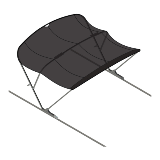
B. SureShade Power Bimini C. Bimini top (canvas) D. Boot (bimini top) The SureShade Power Bimini top can be operated in four different positions. Full Open Position Remove protective boot. Press and hold the switch until motors turn off—do not release switch until both actuator motors turn off. -
Page 14: Step 1 - Rf Receiver
INSTALLATION NOTE: The RF Remote Control is an optional control, but not required to be installed for the system to operate. OPTIONAL RF REMOTE CONTROL STEP 1 – RF RECEIVER TOOLS REQUIRED: 1. Cordless or electric drill or screw gun 2. - Page 15 INSTALLATION OPTIONAL RF REMOTE CONTROL STEP 2 – WIRE RF RECEIVER TOOLS REQUIRED: 1. None PARTS REQUIRED: A. Actuator motors B. RF receiver C. 6 Amp short stop breaker D. DPDT reversing toggle switch (if not previously installed) E. 3/16" insulated flag spade terminal F.
- Page 16 TOOLS REQUIRED: 1. None PARTS REQUIRED: A. Key-Fob remote BEFORE OPERATING THE POWER BIMINI TOP, THOROUGHLY INSPECT THE AREA AROUND THE ENTIRE BIMINI ASSEMBLY. VERIFY THAT ALL PASSENGERS ARE IN A SAFE POSITION AND THAT NOBODY IS IN AN AREA THAT WILL INTERFERE WITH THE MOTION OF THE BIMINI.
- Page 17 B. SureShade Power Bimini C. Bimini top (canvas) D. Boot (bimini top) The SureShade Power Bimini top can be operated in four different positions. Full Open Position Remove protective boot. Press the Open button on the key-fob until motion begins and then release. Motion will continue and motors will automatically turn off.
- Page 18 Install the canvas top onto the power bimini top. The canvas top has securing straps with female snaps located at the bow port and starboard corners and aft port and starboard corners. Securing straps prevent undo billowing of the top when installing the boot.
- Page 19 2. Appropriate drive bit PARTS REQUIRED: A. Male snaps with self-tapping screws B. SureShade Power Bimini C. Bimini top (canvas) NOTE: The male snaps with self-tapping screws are provided by the bimini top (canvas) manufacturer. If male snaps did not come with the canvas, contact the canvas manufacturer.
-
Page 20: Maintenance
PARTS REQUIRED: A. None If the power bimini top will not close (retract) a manual override of the power bimini top must be done before putting the pontoon underway. Unzip the front pocket of the bimini canvas. Have a second person push forward on the rear frame to relieve some pressure off the canvas and hold up the rear and middle frames when the canvas is unzipped. -
Page 21: Fabric Care
MAINTENANCE FABRIC CARE TOOLS REQUIRED: 1. Garden hose 2. Large bucket to hold five gallons of water 3. Mild dish soap 4. Soft bristle brush PARTS REQUIRED: A. None Use clear water to consistently hose off the bimini top fabric during the boating season. If necessary, do a deeper clean of the bimini top fabric as follows: If necessary, remove the boot and fully open (extend) the bimini top. - Page 22 Manual information may be distributed as a complete document only, unless Lippert Components provides explicit consent to distribute individual parts. All manual information is subject to change without notice. Revised editions will be available for free download at lci1.com. Manual information is considered factual until made obsolete by a revised version. Please recycle all obsolete materials.
Need help?
Do you have a question about the Power Bimini and is the answer not in the manual?
Questions and answers