Advertisement
Quick Links
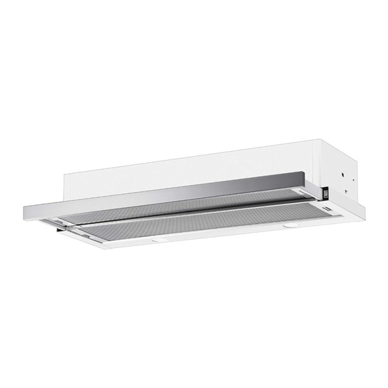
SLIDEOUT RANGEHOOD
I N S T A L L A T I O N
Note: Generic model is shown.
Actual product may differ.
P R O D U C T
161
597 (600 Model)
897 (900 Model)
POWER CORD EXITS
THIS SIDE EITHER
TOP OR BOTTOM
All dimensions are in millimeters
I N S T A L L A T I O N
Please read the entire instructions
before installing the rangehood.
STEP 1. PRELIMINARY
INSTRUCTIONS
The following steps will help you to easily install your rangehood
in the manner most suited to your kitchen. Please read the
complete instructions before installing your rangehood. Plan your
ducting method and mounting arrangements, choose your electrical
connection, then simply follow these instructions.
When installing the rangehood, the lower edge of the unit must
be a minimum of 600mm (650mm for gas cooker)
above the cooking range.
The recommended position for the hood is 650mm above
the hotplates.
I N S T R U C T I O N
D I M E N S I O N S
280
33 or 80
462
O F
U N I T
not less
than 650 mm
GAS
BURNER
STEP 2. PREPARING THE RANGEHOOD
FOR INSTALLATION
If the rangehood is to be installed
KNOCKOUTS
as a ducted hood, remove the
appropriate duct knockout.
See Diagram 1.
Refer to Steps 3 & 4 for MOUNTING
METHODS and ALTERNATIVE DUCTING
METHODS.
If the rangehood is to be installed as a
recirculating hood, first ensure the
overhead cabinets are built according
to Diagram 2, and
i) Remove Cover Tape 'A'. See Diagram 1
ii) if 80mm handle is not installed. Remove
Front Fascia 'B' by undoing 3 screws on
the fascia. See Diagram 1
.
iii) Replace 'B' with Replacement Front Panel 'C'
constructed of same or similar material as
cupboard doors. See diagram 2 for height of panel.
iv) Now install the rangehood in accordance with step 3.
STEP 3. MOUNTING THE RANGEHOOD
The Rangehood can be mounted in two ways, top
or sides.
TOP MOUNTING
Fix rangehood to a shelf mounted
at the right height in your wall
units, by drilling 4 holes (see
Diagram 3) and fixing with 4
screws supplied. The position of
the holes can quickly be found
using the installation sheet
provided.
SIDE MOUNTING
See installation sheet provided.
The rangehood's plug can be easily plugged into the nearest wall socket, or if connected
directly into the house wiring a registered electrician is required.
DIAGRAM 3
For top ducting cut hole to suit duct size
Dimensions shown are for UNIDUCT
DIAGRAM 1
A
DIAGRAM 2
WALL
111024 Issue C
ECN: 07 039
B
C
Advertisement

Related Manuals for Fisher & Paykel HS60


Summary of Contents for Fisher & Paykel HS60
- Page 1 SLIDEOUT RANGEHOOD STEP 2. PREPARING THE RANGEHOOD FOR INSTALLATION If the rangehood is to be installed DIAGRAM 1 KNOCKOUTS as a ducted hood, remove the I N S T A L L A T I O N I N S T R U C T I O N appropriate duct knockout.
- Page 2 STEP 4. ALTERNATIVE DUCTING METHODS Some authorities require rangehoods to be vented outside. DUCTED models comply with WARNING this requirement in every respect. DUCTING OPTIONS •This appliance is not intended for use by young children or infirm persons without supervision. •Young children should be supervised to ensure that they do not play with the appliance.
- Page 3 Align with inside left cupboard wall Align with inside right cupboard wall door front Align cupboard Align left hand front corner Align right hand front corner...
- Page 4 Installation sheet Top Mounting (Preferred installation method) 1. Use template provided on the reverse page. 2. Cut or fold along the dotted edge. 3. Align template with the inside cupboard wall and the front of the cupboard door and drill holes. Keep opposite side door to which you are drilling closed in order to align template correctly.
Need help?
Do you have a question about the HS60 and is the answer not in the manual?
Questions and answers