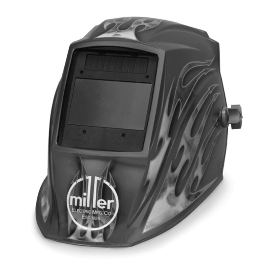
Miller Elite Series Manual
Auto-darkening helmets
Hide thumbs
Also See for Elite Series:
- Operating instruction (32 pages) ,
- Owner's manual (32 pages) ,
- Owner's manual (32 pages)
Summary of Contents for Miller Elite Series
- Page 1 OM-217 741D 2007−01 ® Auto-Darkening Helmets Model: Elitet To help us serve you better, go to www.MillerWelds.Com/HelmetReg/...
-
Page 2: Table Of Contents
TABLE OF CONTENTS SECTION 1 − SAFETY PRECAUTIONS − READ BEFORE USING ..... . . 1-1. Symbol Usage ............. 1-2. -
Page 3: Section 1 − Safety Precautions − Read Before Using
SECTION 1 − SAFETY PRECAUTIONS − READ BEFORE USING Y Warning: Protect yourself and others from injury — read and follow these precautions. 1-1. Symbol Usage Means Warning! Watch Out! There are possible hazards with this procedure! The possible hazards are shown in the ad- joining symbols. -
Page 4: Section 2 − Specifications
Shuts lens Off 15−20 minutes after last arc is struck Low Battery Indicator Red LED light illuminates to indicate 2−3 days remaining battery life Power Supply CR2450 Lithium Batteries (Miller Part No. 217 043) Sensors Independent/Redundant (Four) Operating Temperature 14_F to 131_F / −10_C to +55_C When stored in extremely cold temperatures, warm helmet to ambient temperature before welding. -
Page 5: Section 3 − Operating Instructions
SECTION 3 − OPERATING INSTRUCTIONS 3-1. Helmet Controls Reset Button (See Section 3-2) Low Battery Indicator (See Section 3-2) Variable Shade Control (See Section 3-4) Sensitivity Control (See Section 3-5) Lens Delay Control (See Section 3-3) 804 847 OM-217 741 Page 3... -
Page 6: Reset Button And Low Battery Indicator
The low battery indicator lights when 2−3 days of battery life remain. If battery power is low, replace with CR2450 lithium batteries (2 required) (Miller Part No. 217 043) (see Section 3-3. Lens Delay Control Lens Delay Control The lens delay control is used to adjust the time for the lens to switch to the clear state after welding. -
Page 7: Variable Shade Control (No. 8 − 13)
3-4. Variable Shade Control (No. 8 − 13) Variable Shade Control (No. 8 − 13) Use the control to adjust the lens shade in the darkened state. Use the table below to select proper shade control setting based on your welding process. Start at shade 12 and adjust lighter to suit the welding application and your personal preference. -
Page 8: Sensitivity Control
3-5. Sensitivity Control Sensitivity Control Weld Mode Use control to make the lens more respon- sive to different light levels in various weld- ing processes. Use a Mid-Range or 30−50% sensitivity setting for most ap- plications. It may be necessary to adjust helmet sensi- tivity to accommodate different lighting con- ditions or if lens is flashing On and Off. -
Page 9: Section 4 − Adjusting Headgear
SECTION 4 − ADJUSTING HEADGEAR There are four headgear adjust- ments: headgear top, tightness, angle adjustment, and distance adjustment. Headgear Top Adjusts headgear for proper depth on the head to ensure correct bal- ance and stability. Headgear Tightness To adjust, push in the adjusting knob located on the back of the headgear and turn left or right to desired tight- ness. -
Page 10: Section 5 − Replacing The Lens Covers
SECTION 5 − REPLACING THE LENS COVERS Y Never use the auto-dark- ening lens without the in- side and outside lens covers properly installed. Welding spatter will dam- age the auto-darkening lens void warranty. Front Lens Gasket Be sure flat side of gasket faces lens cover holder. -
Page 11: Section 6 − Replacing The Battery
Replace with CR2450 lithium type batteries (2 required) or equivalent (Miller Part No. 217043). Be sure Positive (+) side of the battery faces up (toward inside of helmet). Reinstall the battery trays. To test, press the Reset button. -
Page 12: Section 7 − Installing Optional Magnifying Lens
SECTION 7 − INSTALLING OPTIONAL MAGNIFYING LENS Optional Magnifying Lens Starting at the bottom, slide magni- fying lens into the helmet retaining brackets. Align the magnifying lens with the auto-darkening lens as- sembly. D Remove lens holding frame (with auto-darkening lens) from helmet shell. -
Page 13: Section 9 − Troubleshooting
SECTION 9 − TROUBLESHOOTING Trouble Remedy Auto lens not ON – auto- Check batteries and verify they are in good condition and installed lens will not darken mo- properly. Also, check battery surfaces and contacts and clean if mentarily when the Reset necessary. -
Page 14: Section 10 − Parts List
SECTION 10 − PARTS LIST Miller 804 111 Figure 10-1. Elite Series Auto-Darkening Welding Helmet OM-217 741 Page 12... - Page 15 Item Part Description Quantity Figure 10-1. Elite Series Auto-Darkening Welding Helmet ... . 216 331 ..Helmet Shell, Black ......
-
Page 16: Section 11 − Limited Warranty
LIMITED WARRANTY – Subject to the terms and conditions below. Miller Electric Mfg. Co., Appleton, Wisconsin, warrants to its original retail pur- chaser that the new Miller equipment sold after the effective date of this limited warranty is free of defects in material and workmanship at the time it is shipped by Miller. - Page 20 Visit our website at www.MillerWelds.com ® Miller Electric Mfg. Co. An Illinois Tool Works Company 1635 West Spencer Street Appleton, WI 54914 USA © PRINTED IN USA 2007 Miller Electric Mfg. Co.


Need help?
Do you have a question about the Elite Series and is the answer not in the manual?
Questions and answers