
Related Manuals for TSC TC200 Series


Summary of Contents for TSC TC200 Series
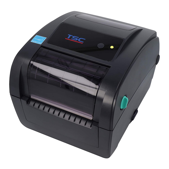
- Page 1 TC200/ TC210/ TC300/ TC310 Series THERMAL TRANSFER / DIRECT THERMAL BAR CODE PRINTER SERVICE MANUAL...
-
Page 2: Table Of Contents
TC200/ TC210/ TC300/ TC310 Series Bar Code Printer Service Manua TABLE OF CONTENT 1. OVERVIEW ............................. 1 1.1 Front View ............................. 1 1.2 Interior View............................3 1.3 Rear View .............................. 4 2. ELECTRONICS ............................5 2.1 Summary of Board Connectors ......................5 2.2 Pin Configuration .......................... -
Page 3: Overview
TC200/ TC210/ TC300/ TC310 Series Bar Code Printer Service Manua 1. OVERVIEW 1.1 Front View For TC210 series For TC200 series LCD display Menu button Feed button LED indicator Navigation button Ribbon access cover Top cover open lever *SD card socket... - Page 4 - The DOS FAT file system is supported for the SD card. - Folders/files stored in the SD card should be in the 8.3 filename format - The miniSD/microSD card to SD card slot adapter is required. For TC200 series SD card spec SD card capacity Approved SD card manufacturer V1.0, V1.1...
-
Page 5: Interior View
TC200/ TC210/ TC300/ TC310 Series Bar Code Printer Service Manua 1.2 Interior View Ribbon rewind hub Ribbon rewind gear Gap sensor (receiver) Media holder Media holder locking switch Gap sensor (transmitter) Print head Ribbon supply hub Top cover support Media guide adjustment button Media guides Black mark sensor Platen roller... -
Page 6: Rear View
TC200/ TC210/ TC300/ TC310 Series Bar Code Printer Service Manua 1.3 Rear View For TC210 series inte rfac Ethernet interface For TC200 series USB interface USB host RS-232C interface Power jack socket Power switch External label entrance chute Parallel interface The interface picture here is for reference only. -
Page 7: Electronics
TC200/ TC300/ TC210/ TC310 Bar Code Printer Service Manual 2. ELECTRONICS 2.1 Summary of Board Connectors For TC200/ TC300 Series Main board Connector Description Remark Power switch Power supply output (24V DC) connector RS-232C connector... - Page 8 TC200/ TC300/ TC210/ TC310 Bar Code Printer Service Manual Centronics port connector USB connector Ethernet connector Print head connector JP12_1 & JP12_2 (TTP-343C) Print head connector JP30_1 & JP30_2 (TTP-245C / 244CE) Micro processor 5V DC connector JP22 Buzzer (Factory option) RTC battery (Factory option) SD card slot Motor temp.
- Page 9 TC200/ TC300/ TC210/ TC310 Bar Code Printer Service Manual Description Voltage Power 3.3V LED light on: 1.1~1.4V LED green LED light off: 1.6~1.9V LED light on : 1.4~1.7V LED red LED light off: 1.8~2.1V 0V: Push key Feed switch 3.3V: Stand-by Peel-off sensor connector JP19 Description...
- Page 10 TC200/ TC300/ TC210/ TC310 Bar Code Printer Service Manual Gap sensor receiver connector JP34 Description Voltage Power 3.3V Gap sensor receiver AD 0~3.3V Ribbon encoder sensor connector JP20 RFID module connector (Factory option) JP38 Main board bottom Connector Description Remark Firmware recover card connector JP37...
- Page 11 TC200/ TC300/ TC210/ TC310 Bar Code Printer Service Manual For TC210/ TC310 Series Main board Connector Description Remark Power switch SW800 Power supply output (24V DC) connector B800 RS-232C connector J203 USB host connector/ Centronics port connector (Option) J204 / J200 USB connector J205 Ethernet connector...
- Page 12 TC200/ TC300/ TC210/ TC310 Bar Code Printer Service Manual Print head connector J401 & J403 (TC310) Print head connector J402 & J404 (TC210) Micro processor LCD MODULE connector J700 Buzzer (Factory option) B600 RTC battery (Factory option) BT800 SD card slot J100 Motor temp.
- Page 13 TC200/ TC300/ TC210/ TC310 Bar Code Printer Service Manual Head open sensor connector J601 Description Voltage Power 3.3V 0~1.4V: Head close Head open sensor receiver 1.7~3.3V: Head open Gap sensor emitter connector J602 Description Voltage Power 3.3V Emitter on : 2.1~2.3V Gap sensor emitter Emitter off: 2.6~2.8V Black mark sensor connector...
-
Page 14: Pin Configuration
TC200/ TC300/ TC210/ TC310 Bar Code Printer Service Manual 2.2 Pin Configuration RS-232C CONFIGURATION +5 V CONFIGURATION Centronics SPP Mode Nibble In/Out Function A low on this line indicates that there are valid data at the host. When this pin is de-asserted, the +ve Strobe clock edge should be used to shift the data into the device. - Page 15 TC200/ TC300/ TC210/ TC310 Bar Code Printer Service Manual direction, it functions as PtrBusy. Paper Out / When low, device acknowledges reverse request. Select Extensibility flag Ground Ground No Defined 16-17 Ground Ground No Defined 19-30 Ground Ground No Defined A low set by the device indicates that the reverse Error / Fault data is available...
-
Page 16: Mechanism
TC200/ TC300/ TC210/ TC310 Bar Code Printer Service Manual 3. MECHANISM Please turn off the power switch and unplug the power adapter before replacing parts. 3.1 Replacing LED (Or LCD) Module 1. Open the printer top cover. Remove 6 screws from the top inner cover. - Page 17 TC200/ TC300/ TC210/ TC310 Bar Code Printer Service Manual 4. Remove 5 screws to replace the LCD module. (Or remove 2 screws to replace the LED module.) Reassemble the parts in the reverse procedure. LCD module LED module...
-
Page 18: Replacing The Main Board
TC200/ TC300/ TC210/ TC310 Bar Code Printer Service Manual 3.2 Replacing the Main Board 1. Turn the printer upside down and use the Phillips screwdriver to remove 6 screws on lower cover. Remove the lower cover. 2. Remove 1 screw on the main board. -
Page 19: Replacing The Head Open Sensor
TC200/ TC300/ TC210/ TC310 Bar Code Printer Service Manual 3.3 Replacing the Head Open Sensor 1. Refer to section 3.2 to remove the lower cover. 2. Disconnect the connector on the main board. Note: The connector located on J601 for TC210/TC310 series. The connector located on JP16 for TC200/TC300 series. -
Page 20: Replacing The Platen Roller Assembly
TC200/ TC300/ TC210/ TC310 Bar Code Printer Service Manual 3.4 Replacing the Platen Roller Assembly 1. Open the printer top cover to remove the front panel. 2. Disengage the platen holder tabs to the lower inner cover by pulling out the right side and left side tabs toward the center of platen and rotates 90 degrees. -
Page 21: Replacing The Print Head Assembly
TC200/ TC300/ TC210/ TC310 Bar Code Printer Service Manual 3.5 Replacing the Print Head Assembly 1. Open the printer top cover. 2. Remove 2 screws that hold the print head bracket. 3. Open the ribbon access cover. Let print head bracket drops into its place. - Page 22 TC200/ TC300/ TC210/ TC310 Bar Code Printer Service Manual 6. Remove the print head harness cover to connect the print head harness for new print head module then install back the cover. 7. Insert the new print head module spring plate into the ribbon base print head spring plate slot.
-
Page 23: Replacing The Stepping Motor
TC200/ TC300/ TC210/ TC310 Bar Code Printer Service Manual 3.6 Replacing the Stepping Motor 1. Refer to section 3.2 to remove the lower cover. 2. Disconnect the stepping motor connector from the main board. TC210/TC310 series. (J501) TC200/TC300 series. (JP14) 3. -
Page 24: Replacing The Black-Mark Sensor Module
TC200/ TC300/ TC210/ TC310 Bar Code Printer Service Manual 3.7 Replacing the Black-mark Sensor Module 1. Refer to section 3.2 to remove the main board. 2. Remove 2 screws to release the black mylar. 3. Remove 1 screw on the black-mark sensor fixing plate. -
Page 25: Replacing The Gap Sensor (Transmitter)
TC200/ TC300/ TC210/ TC310 Bar Code Printer Service Manual 3.8 Replacing the Gap Sensor (Transmitter) 1. Refer to section 3.2 to remove the main board. 2. Remove 2 screws to release the black mylar. 3. Remove 1 screw on the sensor fixing plate to replace the sensor PCB. -
Page 26: Replacing The Media Holder
TC200/ TC300/ TC210/ TC310 Bar Code Printer Service Manual 3.9 Replacing the Media Holder 1. Refer to section 3.2 to remove the main board. 2. Remove the black mylar. 3. Remove 2 screws to take off the upper circle cover as shown. - Page 27 TC200/ TC300/ TC210/ TC310 Bar Code Printer Service Manual 5. Remove 4 screws to replace the media holder assembly. 6. Push the media holder base assembly to the end place and install the cover shaft first for installing the spiral sprint assembly back.
- Page 28 TC200/ TC300/ TC210/ TC310 Bar Code Printer Service Manual 8. Use needle-nose pliers to install the spiral spring back. 9. Screw 2 screws to replace the upper cover of sprial spring assembly. Reassemble the parts in the reverse procedure.
-
Page 29: Peel-Off Module Installation (Option)
TC200/ TC300/ TC210/ TC310 Bar Code Printer Service Manual 3.10 Peel-off Module Installation (Option) 1. Refer to section 3.2 to remove the lower cover. Open the top cover and pull up the front panel from the printer. 2. Disengage one of platen holder tab from lower inner cover and rotate the tab 90 degrees to install the peel-off... - Page 30 TC200/ TC300/ TC210/ TC310 Bar Code Printer Service Manual 4. Thread the 5-pin peel-off module harness through the front slot of lower inner cover. 5. Plug in the peel-off module harness connector to the 5-pin red socket on the main board.
- Page 31 TC200/ TC300/ TC210/ TC310 Bar Code Printer Service Manual 7. Put back the lower inner cover. Fasten 6 screws at the lower inner cover. Place the printer in the flat and secured desktop for media loading and printing. Note: Please refer to user’s manual for loading media in peel-off mode.
-
Page 32: Cutter Module Installation (Option)
TC200/ TC300/ TC210/ TC310 Bar Code Printer Service Manual 3.11 Cutter Module Installation (Option) 1. Refer to section 3.2 to remove the lower cover. Open the top cover and pull up the front panel from the printer. 2. Thread the cutter module 8-pin harness through the front slot of lower inner cover. - Page 33 TC200/ TC300/ TC210/ TC310 Bar Code Printer Service Manual 4. Put back the lower inner cover. Place the cutter module into both side notches of lower inner cover as picture below, then push cutter to lock into the lower inner cover.
-
Page 34: Troubleshooting
TC200/ TC300/ TC210/ TC310 Bar Code Printer Service Manual 4. TROUBLESHOOTING The following guide lists the most common problems that might be encountered when operating this bar code printer. If the printer still does not function after all suggested solutions have been invoked, please contact the Customer Service Department of your purchased reseller or distributor for assistance. - Page 35 TC200/ TC300/ TC210/ TC310 Bar Code Printer Service Manual * The port specified in the is 9600,n,8,1. Windows driver is not * If using the Ethernet cable, correct. - Check if the Ethernet RJ-45 connector green LED is lit on. - Check if the Ethernet RJ-45 connector amber LED is blinking.
- Page 36 TC200/ TC300/ TC210/ TC310 Bar Code Printer Service Manual Can’t downloading the file * The space of memory is to memory (FLASH / * Delete unused files in the memory. full. DRAM/CARD) * SD card is damaged. * Use the supported capacity SD card. * SD card doesn’t insert SD card is unable to use * Insert the SD card again.
- Page 37 TC200/ TC300/ TC210/ TC310 Bar Code Printer Service Manual * Calibrate the sensor sensitivity again. * Set the correct label size and gap size. * Use DiagTool to fine tune the parameter of Shift Y. * If using the software BarTender, please set the vertical offset in the driver.
-
Page 38: Maintenance
TC200/ TC300/ TC210/ TC310 Bar Code Printer Service Manual 5. MAINTENANCE This session presents the clean tools and methods to maintain your printer. 1. Please use one of following material to clean the printer. Cotton swab Lint-free cloth ... - Page 39 TC200/ TC300/ TC210/ TC310 Bar Code Printer Service Manual Please use 100% Ethenol. DO NOT use medical alcohol, which may damage the printer head. Regularly clean the print head and supply sensors once change a new ribbon to keep printer performance and extend printer life.
-
Page 40: Update History
TC200/ TC300/ TC210/ TC310 Bar Code Printer Service Manual UPDATE HISTORY Date Content Editor 2015/10/21 Modify section 1.1 (Recommended SD card specification) Camille... - Page 41 9F., No.95, Minquan Rd., Xindian Dist., No.35, Sec. 2, Ligong 1st Rd., Wujie Township, New Taipei City 23141, Taiwan (R.O.C.) Yilan County 26841, Taiwan (R.O.C.) TEL: +886-2-2218-6789 TEL: +886-3-990-6677 FAX: +886-2-2218-5678 FAX: +886-3-990-5577 Web site: www.tscprinters.com E-mail: printer_sales@tscprinters.com TSC Auto ID Technology Co., Ltd. tech_support@tscprinters.com...
Need help?
Do you have a question about the TC200 Series and is the answer not in the manual?
Questions and answers