
Related Manuals for TSC TTP-244 Pro Series


Summary of Contents for TSC TTP-244 Pro Series
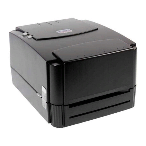
- Page 1 TTP-244 Pro Series THERMAL TRANSFER / DIRECT THERMAL BAR CODE PRINTER USER’S MANUAL...
- Page 2 Information in this document is subject to change without notice and does not represent a commitment on the part of TSC Auto ID Technology Co. No part of this manual may be reproduced or transmitted in any form or by any means, for any purpose other than the purchaser’s personal use, without the expressed...
- Page 3 Agency Compliance and Approvals EN 55022, Class A EN 55024 EN 60950-1 FCC part 15B, Class A AS/NZS CISPR 22, Class A EN 60950-1 GB 4943.1 GB 9254 GB 17625.1 Wichtige Sicherheits-Hinweise 1. Bitte lesen Sie diese Hinweis sorgfältig durch. 2.
- Page 4 CE WARNING: This is a class A product. In a domestic environment this product may cause radio interference in which case the user may be required to take adequate measures. FCC WARNING: This device complies with Part 15 of the FCC Rules. Operation is subject to the following two conditions: (1) this device may not cause harmful interference, and (2) this device must accept any interference received, including interference that may cause undesired operation...
-
Page 5: Table Of Contents
Contents 1. Introduction......................1 1.1 Product Introduction ..................1 1.2 Product Features ....................2 1.2.1 Printer Standard Features ....................2 1.2.2 Printer Optional Features ....................3 1.3 General Specifications..................4 1.4 Print Specifications ................... 4 1.5 Ribbon Specifications ..................4 1.6 Media Specifications .................. - Page 6 5.1 Start the Diagnostic Tool ................27 5.2 Printer Function ....................28 6. Troubleshooting ....................29 7. Maintenance ......................30 Revise History ......................31 - v -...
-
Page 8: Introduction
To print label formats, please refer to the instructions provided with your labeling software; if you need to write the custom programs, please refer to the TSPL/TSPL2 programming manual that can be found on the accessories CD-ROM or on TSC website at http://www.tscprinters.com. -
Page 9: Product Features
1.2 Product Features 1.2.1 Printer Standard Features The printer offers the following standard features. Product standard feature Thermal transfer or direct thermal printing Black mark reflective sensor Gap transmissive sensor Ribbon end sensor 2 buttons 3 LED for printer status (Power, Error, On-line) 32-bit RISC CPU USB 2.0 (full speed) &... -
Page 10: Printer Optional Features
Code page Codepage 437 (English - US) Codepage 737 (Greek) Codepage 850 (Latin-1) Codepage 852 (Latin-2) Codepage 855 (Cyrillic) Codepage 857 (Turkish) Codepage 860 (Portuguese) Codepage 861 (Icelandic) Codepage 862 (Hebrew) ... -
Page 11: General Specifications
○ SD card reader for memory expansion up to 4G ○ 3” core label spindle ○ KP-200 Plus keyboard ○ KU-007 Plus programmable smart keyboard 1.3 General Specifications General Specifications Physical 232 mm (W) x 156 mm (H) x 288 mm (D) dimensions Enclosure ABS plastic... - Page 12 Ribbon length 300 m Ribbon core inside 1” core diameter Ribbon width 40 mm ~ 110 mm (1.6” ~ 4.3”) Ribbon wound type Ink coated outside Note: The maximum length of ribbon depends on its thickness and core outside diameter. The formula below defines the correlation between ribbon roll length and ribbon core diameter.
-
Page 13: Media Specifications
1.6 Media Specifications Media Specifications Label roll capacity 110 mm (4.33”) OD Media core diameter 25.4 ~ 76.2 mm (1” ~ 3”) Continuous, die-cut, black mark, External fan- Media type fold, notched Media wound type Outside wound Media width 25.4 ~ 112 mm (1.0” ~ 4.4”) Media thickness 0.06 ~ 0.25 mm (2.36 ~ 9.84 mil) Label length... -
Page 14: Various Sensor
1.7 Various Sensor Gap Sensor The gap sensor detects a label gap to locate the top of form of the next label. The sensor is mounted 4 mm off the center line of the main mechanism. In case of Label Black Mark Sensor The black mark sensor locates the position of label by emitting infrared rays onto the black mark at the back of the ticket. - Page 15 Ribbon End Sensor The sensor detects the end portion of the ribbon. The ribbon end must be transparent. - 8 -...
-
Page 16: Operations Overview
2. Operations Overview 2.1 Unpacking and Inspection This printer has been specially packaged to withstand damage during shipping. Please carefully inspect the packaging and printer upon receiving the bar code printer. Please retain the packaging materials in case you need to reship the printer. Unpacking the printer, the following items are included in the carton. -
Page 17: Printer Overview
2.2 Printer Overview 2.2.1 Front View PAUSE button PWR., ON-LINE and ERR. indicators FEED button Cover release button Label dispense opening - 10 -... -
Page 18: Interior View
2.2.2 Interior View inter face inte Printer cover (in open position) PAUSE button PWR., ON-LINE, ERR. indicators FEED button Ribbon supply spindle Fixing tabs Label supply roll spindle Ribbon mechanism Ribbon rewind spindle Printer carriage release lever Media sensor Adjustable label guide Platen - 11 -... -
Page 19: Rear View
2.2.3 Rear View inte Power on/off switch Power supply DC jacket RS-232C interface Label insert opening (For use with external media) USB interface Centronics interface (Factory option) Note: The interface picture here is for reference only. Please refer to the product specification for the interfaces availability. -
Page 20: Led Indicators And Buttons
2.3 LED Indicators and Buttons 2.3.1 LED Indication Indication LEDs The green PWR. indicator illuminates when the PWR. (POWER) Indicator POWER switch is turned on. The green ON-LINE indicator illuminates when the printer is ready to print. When PAUSE button is ON-LINE Indicator pressed, the ON-LINE indicator flashes. -
Page 21: Setup
3. Setup 3.1 Setting up the Printer 1. Place the printer on a flat, secure surface. 2. Make sure the POWER switch is off. 3. Connect the printer to the computer mainframe with the RS-232C or USB cable. 4. Plug the power cord into the power jacket at the rear of the printer, and then plug the power cord into a properly... -
Page 22: Loading The Media
3.2 Loading the Media 1. Open the printer cover. 2. Disengage the printer carriage by pulling the printer carriage release lever on the left side of the platen. 3. Slide the label supply roll spindle through the core of a label roll and attach the fixing tabs onto the spindle. - Page 23 ERR. LED will flash. Reload the ribbon or media without turning off the printer power. Press the FEED button three or four times until the ON-LINE LED illuminates. The printing job will be resumed without data loss. Note: Please refer to videos on TSC YouTube or software/driver CD disk. - 16 -...
-
Page 24: Loading The Ribbon
3.3 Loading the Ribbon Place an empty paper core on the ribbon rewind spindle. Insert the left side first. Mount the ribbon rewind paper core on the front hubs. Please be noted that the bigger hub side with 4 ribs must be installed toward the right side of ribbon mechanism. - Page 25 Please be noted that the bigger hub side with 4 ribs must be installed toward the right side of ribbon mechanism. Disengage the printer carriage by pulling the carriage release lever upwards. Following the direction of the RIBBON label, pull the transparent ribbon leader to the front from under the ribbon mechanism.
- Page 26 Please install ribbon and media and close print head mechanism prior to turn on power. Printer will determine direct thermal or thermal transfer mode automatically while turning on printer power. Please refer to videos on TSC YouTube or software/driver CD disk. - 19 -...
-
Page 27: Install Sd Memory Card (Option)
3.4 Install SD Memory Card (Option) 1. Open the memory card cover. 2. Plus the SD memory card module on the main board. 3. Install the SD memory card. 4. Close the memory card cover. - 20 -... - Page 28 * Recommended SD card specification. SD card spec SD card capacity Approved SD card manufacturer V1.0, V1.1 128 MB SanDisk, Transcend V1.0, V1.1 256 MB SanDisk, Transcend, Panasonic V1.0, V1.1 512 MB SanDisk, Transcend, Panasonic V1.0, V1.1 1 GB SanDisk, Transcend, Panasonic V2.0 SDHC CLASS 4 4 GB V2.0 SDHC CLASS 6 4 GB SanDisk, Transcend, Panasonic...
-
Page 29: Using Printer
2. Gap sensor calibration 3. Printer initialization Note: Please refer to videos on TSC YouTube or software/driver CD disk. 4.1.1 Self Test and Dump Mode Install the label first. Press the FEED button and then turn on the printer power. Do not release the FEED button until the printer feeds labels. - Page 30 Self-test printout Model name F/W version Firmware checksum Printer S/N TSC configuration file System date System time Printed mileage (meter) Cutting counter Print speed (inch/sec) Print darkness Label size (inch) Gap distance (inch) Gap/black mark sensor intension Code page Country code...
-
Page 31: Dump Mode
Dump Mode After the self test, the printer enters the dump mode. In this mode, any characters sent from the host computer will be printed in two columns, as shown. The characters received will be shown in the first column, and their corresponding hexadecimal values, in the second. This is often helpful to users for the verification of programming commands or debugging of printer programs. -
Page 32: Printer Initialization
2. Hold down the PAUSE button then turn on printer power. Release PAUSE button when the printer feeds labels. Do not turn off printer power until the printer stops and two green LEDs light on. Note: Black mark sensor has fixed sensitivity. It is no need to calibrate the black mark sensor 4.1.3 Printer Initialization Printer initialization sets printer parameters to default values. - Page 33 Serial Port Settings 9600 bps, none parity, 8 data bits, 1 stop bit Code Page Country Code Clear Flash Memory - 26 -...
-
Page 34: Diagnostic Tool
5. Diagnostic Tool TSC’s Diagnostic Utility is an integrated tool incorporating features that enable you to explore a printer’s settings/status; change a printer’s settings; download graphics, fonts and firmware; create a printer bitmap font; and send additional commands to a printer. With the aid of this powerful tool, you can review printer status and setting in an instant, which makes it much easier to troubleshoot problems and other issues. -
Page 35: Printer Function
5.2 Printer Function 1. Connect the printer and computer with a cable. 2. Select the PC interface connected with bar code printer. USB cable RS-232 cable The default interface setting is USB interface. If USB interface is connected with printer, no other settings need to be changed in the interface field. -
Page 36: Troubleshooting
6. Troubleshooting The following guide lists the most common problems that may be encountered when operating this bar code printer. If the printer still does not function after all suggested solutions have been invoked, please contact the Customer Service Department of your purchased reseller or distributor for assistance. -
Page 37: Maintenance
7. Maintenance This session presents the clean tools and methods to maintain your printer. 1. Please use one of following material to clean the printer. Cotton swab Lint-free cloth Vacuum / Blower brush 100% Ethanol or Isopropyl Alcohol 2. -
Page 38: Revise History
Revise History Date Content Editor 2015/3/12 Modify section 1 & 2 Camille - 31 -... - Page 39 9F., No.95, Minquan Rd., Xindian Dist., No.35, Sec. 2, Ligong 1st Rd., Wujie Township, New Taipei City 23141, Taiwan (R.O.C.) Yilan County 26841, Taiwan (R.O.C.) TEL: +886-2-2218-6789 TEL: +886-3-990-6677 FAX: +886-2-2218-5678 FAX: +886-3-990-5577 Web site: www.tscprinters.com E-mail: printer_sales@tscprinters.com TSC Auto ID Technology Co., Ltd. tech_support@tscprinters.com...
Need help?
Do you have a question about the TTP-244 Pro Series and is the answer not in the manual?
Questions and answers